
Related Manuals for Nordson EP 11


Summary of Contents for Nordson EP 11
- Page 1 Hot Melt Applicators EP 11 / EP 11 N EP 12 V / EP 12 L / EP 12 RV Manual P/N 317091G - English - Issued 03/11 NORDSON ENGINEERING GMBH LÜNEBURG GERMANY...
- Page 2 ContourCoat, Controlled Fiberization, Control Weave, CPX, cSelect, Cyclo‐Kinetic, DispensLink, DropCure, Dry Cure, DuraBraid, DuraCoat, e.dot+, E‐Nordson, Easy Clean, EasyOn, EasyPW, Eclipse, Equalizer, EquiBead, Exchange Plus, FillEasy, Fill Sentry, Flow Coat, Fluxplus, G‐Net, G‐Site, Get Green With Blue, Gluie, Ink‐Dot, IntelliJet, iON, Iso‐Flex, iTrend, KVLP, Lacquer Cure, Maxima, Mesa, MicroFin, MicroMax, Mikros, MiniBlue, MiniEdge,...
-
Page 3: Table Of Contents
....EP 11‐02, L‐design ........ - Page 4 ........E 2011 Nordson Corporation P/N 317091G...
-
Page 5: Safety Instructions
Introduction Intended Use Hot melt applicators in the series EP 11 and EP 12 may be used only for surface application of hot melt adhesives. The maximum material pressure may not exceed 70 bar (7 MPa / 1015 psi). -
Page 6: Residual Risks
The illustrations show only the essential components of the applicator. Refer to the technical drawing for additional components and details. Definition of Term(s) Applicator The term application head is also used in Nordson literature. Melter General term for tank melters and bulk melters. Control Module The term module is also used in Nordson literature. -
Page 7: Description Of Components / Functioning
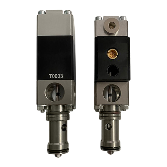
Applicators Description of Components / Functioning EP 11‐02, L‐design Fig. 1 1 Suction stem control module * 5 Control air connection 8 Nozzle 2 Solenoid valve 6 Mounting bracket 9 Hose connection 3 Solenoid valve plug 7 Body 10 Filter cartridge 4 Cordset Note: There are separate manuals available for components marked with an asterisk (*). -
Page 8: Ep 12-01, V-Design
6 Hose connection 9 Nozzle 3 Solenoid valve plug 7 Mounting bracket 10 Cordset 4 Control air connection Note: There are separate manuals available for components marked with an asterisk (*). E 2011 Nordson Corporation P/N 317091G EP11 / EP 12... -
Page 9: Ep 11 N
Applicators EP 11 N Fig. 3 1 Solenoid valve plug 5 Mounting bracket 8 Hose connection 2 Solenoid valve 6 Body 9 Filter cartridge 3 Control air connection 7 Nozzle 10 Cordset 4 Suction stem control module * Note: There are separate manuals available for components marked with an asterisk (*). -
Page 10: Material Flow
The V design of the EP 12 allows two control modules to be assigned for each application zone. The material paths are the same length. The control modules perform alternating applications, meaning that extremely brief pauses between applications are possible. E 2011 Nordson Corporation P/N 317091G EP11 / EP 12... -
Page 11: Suction Stem Control Module
ID Plate Applicator type Nordson order number Serial number Operating voltage V = Volt Power consumption W = Watt oper. temp. max. Maximum operating temperature EP11 / EP 12 P/N 317091G E 2011 Nordson Corporation... -
Page 12: Options
Some applications may require that the filter cartridge be omitted. (EP 11) The material must then be filtered in a preceding unit. Nozzle with nozzle tips (EP 11) Nozzle tips allow material bead application. The nozzles are cleaned with a nozzle cleaning set (P/N 254648), a drill and/or a bath. -
Page 13: Installation
Do not store outside! Protect from humidity and dust. Do not lay unit on the nozzle. Protect the nozzle from damage. Disposal When your Nordson product has exhausted its purpose and/or is no longer needed, dispose of it properly according to local regulations. EP11 / EP 12... -
Page 14: Installing
Secure the voltage plug with the clamp if necessary. NOTE: Observe the voltage stated on the ID plate of the solenoid valve. E 2011 Nordson Corporation P/N 317091G EP11 / EP 12... -
Page 15: Lubricated Or Non-Lubricated Compressed Air
NOTE: It must be ensured that no oil from a possibly defective compressor may be permitted to penetrate the compressed air supply. NOTE: Nordson will assume no warranty/liability for damage resulting from unpermitted, temporary lubrication. Operating with Lubricated Compressed Air The control module EP 10 can also be operated with lubricated compressed air. -
Page 16: Pneumatic Connections
Refer to the separate manual Air Manifold Bar with Pressure Accumulator for additional information. NOTE: The exact pressure must be determined for each application. E 2011 Nordson Corporation P/N 317091G EP11 / EP 12... -
Page 17: Connecting Heated Hose
3. Activate the solenoid valve(s) electrically or manually; or pull the trigger of the assembly handgun. Repeat this procedure until no more material flows out. 4. Properly dispose of material according to local regulations. EP11 / EP 12 P/N 317091G E 2011 Nordson Corporation... -
Page 18: Operation
The applicator temperature required is set on the melter (maximum 200 ° C / 392 ° F). Nordson will grant no warranty and assume no liability for damage resulting from incorrect temperature settings. E 2011 Nordson Corporation... -
Page 19: Setting Control Air Pressure
72.5 to 87 psi The exact pressure must be determined for each application. NOTE: The maximum control air pressure may not be exceeded. Nordson will assume no warranty or liability for damage resulting from incorrect pressure settings. Setting Material Pressure The material pressure is generated by the melter pumps. -
Page 20: Positioning The Applicator
Fig. 8. The coating is applied to the tensed substrate. The substrate should not be diverted from a straight path by more than approx. 1 mm when the applicator touches it. Fig. 8 E 2011 Nordson Corporation P/N 317091G EP11 / EP 12... -
Page 21: Coating Closed-Pore Substrate
Fig. 9. However, coating is not performed against the roll but against the tensed substrate. The substrate should not be diverted from a straight path by more than approx. 1 mm when the applicator touches it. Fig. 9 EP11 / EP 12 P/N 317091G E 2011 Nordson Corporation... -
Page 22: Material Application
Applicators Material Application Sample Calculation Nordson recommends following the sample calculation before starting up the applicator and making a note of the application-specific values for application weight and width, substrate speed and pump output capacity. These values can be used to calculate the pump speed and material quantity. The results of the calculations are also entered in the table. -
Page 23: Settings Record
Cleaning agent: Manufacturer Flash point Basic settings Application weight Application width Substrate speed Material quantity Material pressure Output capacity Basic temperature settings Body Heated hose Motor/pump speeds: Motor/pump Notes: Name Date EP11 / EP 12 P/N 317091G E 2011 Nordson Corporation... -
Page 24: Maintenance
2. Place a container under the nozzle(s) of the applicator. 3. Activate the solenoid valves electrically or manually. Repeat this procedure until no more material flows out. 4. Properly dispose of material according to local regulations. E 2011 Nordson Corporation P/N 317091G EP11 / EP 12... -
Page 25: Regular Maintenance
(option) conditions of use require Calibrate Every time the pressure Check the separating mem sensor is removed, more brane for damage and for often if necessary hardened or charred material EP11 / EP 12 P/N 317091G E 2011 Nordson Corporation... -
Page 26: Pur Adhesives
CAUTION: When damaged parts pose a risk to the operational safety of the applicator and/or safety of personnel, switch off the applicator or application system and have the damaged parts replaced by qualified personnel. Use only original Nordson spare parts. External Cleaning External cleaning prevents impurities created during production from causing the unit to malfunction. -
Page 27: Purging With Cleaning Agent
8. Purge applicator (and, when appropriate, melter and hose) with the material currently in use to flush out the cleaning agent. NOTE: Properly dispose of cleaning agent according to local regulations. EP11 / EP 12 P/N 317091G E 2011 Nordson Corporation... -
Page 28: Disassembling And Cleaning Nozzle
NOTE: When using cleaning agents, observe the manufacturer's information! Carefully read the Material Safety Data Sheet for the cleaning agent used. NOTE: Nordson will assume no warranty or liability for damage resulting from incorrect cleaning. 1. Heat applicator until material is soft. -
Page 29: Assembling Nozzle
4. Screw application nozzle back onto the body with the fixing screws (8). NOTE: Tighten fixing screws size M4, property class 70 in three steps, with a total of 2.5 Nm. Use a torque wrench. NOTE: Contact Nordson for information on special models with different screws. Inserting New Shim Plate 1. -
Page 30: Changing Control Module
Observe the instructions in the section Installation on lubricating or not lubricating compressed air. Nordson recommends keeping a supply of control modules to prevent production stoppage. CAUTION: The control module is a high precision, valuable part. Handle... -
Page 31: Cleaning Filter Cartridge
5. Purge the filter bore by allowing the pump to run briefly with material. This rinses out particles of dirt that may still be in the filter bore. 6. Properly dispose of material according to local regulations. EP11 / EP 12 P/N 317091G E 2011 Nordson Corporation... -
Page 32: Replace The Filter Screen
1. Heat the filter cartridge until material is liquid. 2. Turn the unit consisting of pressure relief screw, filter screen and spring counterclockwise out of the filter screw, then replace. NOTE: Nordson recommends keeping a supply of replacement filter cartridges to avoid interruptions in production. Installing Filter Cartridge 1. -
Page 33: Nozzle Filter
5. Purge the filter bore by allowing the pump to run briefly with material. This rinses out particles of dirt that may still be in the filter bore. 6. Properly dispose of material according to local regulations. Fig. 16 EP11 / EP 12 P/N 317091G E 2011 Nordson Corporation... - Page 34 5. Feed material by allowing the pump to run until the material comes out of the applicator free of bubbles. 6. Properly dispose of material according to local regulations. Fig. 17 E 2011 Nordson Corporation P/N 317091G EP11 / EP 12...
- Page 35 6. Properly dispose of cleaning agent according to local regulations. Fig. 18 1 Center tapped hole 4 Filter screen 7 Air relief valve 2 Filter screw 5 Screw plug 8 Nut 3 O‐ring 6 Filter sheath EP11 / EP 12 P/N 317091G E 2011 Nordson Corporation...
- Page 36 2. To screw on, apply high temperature grease to all threads and O‐rings. Refer to page 33, Processing Materials for information on the high-temperature grease. Fig. 19 1 Filter cartridge 3 Hose connection 5 O‐ring 2 Cylinder screw 4 Filter casing E 2011 Nordson Corporation P/N 317091G EP11 / EP 12...
-
Page 37: Processing Materials
NOTE: The grease should not be P/N 394769 10 g mixed with other lubricants. P/N 783959 Tube 250 g Oily/greasy parts must be cleaned before application. P/N 402238 Cartridge 400 g EP11 / EP 12 P/N 317091G E 2011 Nordson Corporation... -
Page 38: Maintenance Record
Applicators Maintenance Record Unit part Activity Date Name Date Name Applicator External inspection and cleaning Control module Nozzle Cleaning Replace nozzle Replace shim plate Filter cartridge Replace E 2011 Nordson Corporation P/N 317091G EP11 / EP 12... -
Page 39: Troubleshooting
Faults in installation Faults in operation Defective cables Loose plug and screw connections. In the column Corrective action, the remark that defective parts should be replaced is generally not included. EP11 / EP 12 P/N 317091G E 2011 Nordson Corporation... - Page 40 Control unit not switched on Switch on Separate manual do not switch Control Unit Valve connecting cable not Check that plug connections Page plugged in or loose are tight Continued... E 2011 Nordson Corporation P/N 317091G EP11 / EP 12...
- Page 41 Material unsuitable Ask manufacturer Data sheet from material manufacturer NOTE: * The open time is the time from when the material leaves the nozzle until it hardens on the substrate. EP11 / EP 12 P/N 317091G E 2011 Nordson Corporation...
-
Page 42: Technical Data
5 to 6 bar 0.5 to 0.6 MPa 72.5 to 87 psi Temperatures 40 ° C 104 ° F Max. ambient temperature 200 ° C 392 ° F Max. operating temperature E 2011 Nordson Corporation P/N 317091G EP11 / EP 12... -
Page 43: Electrical Data
Degree of protection IP 30 Voltage for solenoid valve 24 V 230 V Dimensions and Weights Dimensions (L x W x H) Refer to technical drawing Weight See consignment note EP11 / EP 12 P/N 317091G E 2011 Nordson Corporation... - Page 44 Applicators E 2011 Nordson Corporation P/N 317091G EP11 / EP 12...
Need help?
Do you have a question about the EP 11 and is the answer not in the manual?
Questions and answers