Sign In
Upload
Manuals
Brands
Nordson Manuals
Industrial Equipment
EX Series
Nordson EX Series Manuals
Manuals and User Guides for Nordson EX Series. We have
1
Nordson EX Series manual available for free PDF download: Manual
Nordson EX Series Manual (138 pages)
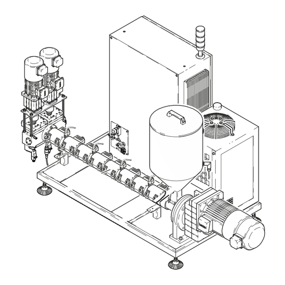
Extruder
Brand:
Nordson
| Category:
Industrial Equipment
| Size: 6 MB
Table of Contents
Table of Contents
3
Safety
11
Safety Alert Symbols
11
Responsibilities of the Equipment Owner
12
Safety Information
12
Instructions, Requirements, and Standards
12
User Qualifications
13
Applicable Industry Safety Practices
13
Intended Use of the Equipment
13
Instructions and Safety Messages
14
Installation Practices
14
Operating Practices
14
Maintenance and Repair Practices
15
Equipment Safety Information
15
Equipment Shutdown
16
Relieving System Hydraulic Pressure
16
De-Energizing the System
16
Disabling the Applicators
16
General Safety Warnings and Cautions
17
Other Safety Precautions
20
First Aid
20
Safety Labels and Tags
21
Introduction
23
Intended Use
23
Area of Use (EMC)
23
Operating Restrictions
23
Unintended Use - Examples
23
Restricted Use
24
Residual Risks
24
Note on Manual
25
Emergency off / Emergency Stop
25
ID Plate
26
Configuration Code
27
Function
29
Description of Components
30
Illustration of
30
Illustration of EX-060
31
Protective Devices
33
Protective Covers
33
Covers
33
Safety Guard
33
Overtemperature Protection
33
Pneumatic Assembly and Pneumatic Bypass
34
Pressure Control / Pressure Monitoring
34
Mechanical Bypass
35
Drive
36
Hopper
36
Filling Area
36
Screw Conveyor
37
Screw Cylinder
37
Heating Cuff
37
Air Cooling
37
Cylinder Feed Cooling
38
Extruder Flange
38
Compensation Bearings / Thrust Bearings
38
Main Switch
39
Black Main Switch (Special Model)
39
Power Switch (with Overcurrent Shutdown)
40
Only for Qualified Personnel
40
EMERGENCY off Button
41
Receptacle
41
Light Tower
41
Door Lock
41
Control Panel
42
Reducing Temperature Inside Electrical Cabinet
42
Electrical Cabinet Ventilation and Cooling Element
42
Electrical Cabinet Cooling Unit (Depending on Application)
42
Cold Plate Cooling
42
Interfaces
42
Field Bus Interface (Option)
42
Metering Station (Option)
43
Piston Pressure Switch
43
Overtemperature Fuse (Behind Electrical Cover)
43
Fuse
43
Thermostat
43
Foam Station Ultra Foammix (Special)
44
Description of Function
45
Examples of Foamed Adhesive Beads
45
Using a Pressure Relief Valve to Prevent Overpressure Malfunction During Longer Breaks in Production
46
Installation
47
Unpacking
47
Transport
47
Storage
47
Removal
47
Disposal
47
Transport
48
Lifting (Unpacked Unit)
48
Lifting the Metering Station
49
Installation Requirements
50
Space Requirement
50
Exhausting Adhesive Vapors
50
Installation Personnel's Experience
50
Setting up
51
If There Is Transport Protection - IMPORTANT
51
Electrical Connections
52
Laying Cable
52
Connecting External Transformer
52
Line Voltage
53
Protective Ground and Fuse Protection
53
External Control/Signal Circuits
53
EMERGENCY off Module (Option)
53
Connecting Interfaces
54
Standard I/O
54
External EMERGENCY off Chain
54
Pilot Voltage Input
54
Field Bus (Option)
55
Example of DP/DP Coupler (Siemens)
55
Example of DP/DP Coupler "PAS153" (Helmholz) - Obsolete
55
Analog Modem for PC Connection
56
PC Connection
56
Pneumatic Connection
56
Pneumatic Bypass (Pressure Relief)
56
Foam Extruder
56
Connecting Heated Hose
57
Using Second Open-End Wrench
57
Connecting
57
Disconnecting
58
On Extruder or Metering Station
58
On Foam Station
58
Relieving Adhesive Pressure (EX)
58
Electrical Cabinet Cooling Unit
59
Connecting Water Chiller (Option)
60
Water Installation
61
Observe When Using Own Cooling Water Supply
61
Water Specification
61
Corrosion Protection
61
Motor Controller with Cold Plate Cooling
62
Measurement and Control Diagram
62
Measurement and Control Diagram (System)
64
Adjusting Mechanical Bypass Valve
65
Piston Pressure Switch KDS 05/120
66
Metering Station (Option) / Foam Station (Special)
66
Foam Station Ultra Foammix (Special)
66
Connecting Compressed Air or Inert Gas
68
Condensate Disposal
68
Pressure Relief Valve with Drip Pan
69
Measurement and Control Diagram (Foam Station)
70
Operation
71
Remaining Dampness of Granulate
71
Adhesive Expiration Date
71
Important Upon Initial Startup
72
Initial Startup
73
Selecting Pressure Control or Speed Control
76
Operation in Manual Mode (Service Mode)
76
Additional Foam Extruder Keys
76
Operation in Automatic Mode
77
Extruder Worm / Pump
77
Applicator
77
Foam Station (Special Feature)
77
During Production
78
Notes on Temperature Setting
78
Standby During Breaks
78
Level Monitoring (Hopper)
78
Dry Run Protection
78
Acknowledging Fault Indications
78
Note on Motor with External Fan
78
Pressure Monitoring
79
Temperature Monitoring
79
Undertemperature Interlock
79
Overtemperature Warning
79
Overtemperature Fault
79
Overtemperature Shutdown
79
Switching System ON/OFF
80
Daily Startup
80
Daily Shutdown
81
Emergency Shutdown
81
Maintenance
83
Risk of Burns
83
Relieving Adhesive Pressure
83
Residual Current Device (RCD) / Earth Leakage Circuit Breaker (ELCB)
84
Shutdown
85
Starting up System Again
85
Changing Type of Adhesive
86
Processing Materials
86
Regular Maintenance
86
Lubricating Plan
88
Visual Inspection for External Damage
89
External Cleaning
89
General Electrical Inspection
89
Ongoing Checks
90
Heater Cartridges
91
Measuring Heater Cartridges
91
Replacing Heater Cartridges
91
Electrical Cabinet Ventilation
91
Gear Pump
92
Retightening Fixing Screws
92
Retightening Gland
92
Metering Station: Maintenance Position of Cover
92
Motor / Gear Box
93
Replacing Motor
93
Changing Lubricant
93
Gear Boxes with Temperature and Level Sensor
94
Compression Bearings (on Models with Lubricating Nipple)
94
Greasing Compression Bearing
94
Thrust Bearing (EX030
95
Installing and Tightening New Belts
95
Tightening
96
What Happens When Belt Tension Is Wrong
96
Heating Cuffs
97
Ceramic Heating Cuffs
97
Micanite Heating Cuffs
97
Pressure Sensor
98
Cleaning Adhesive Bore
98
Cleaning Separating Membrane
98
Screwing in
98
Cleaning Gas Supply Valve (UFM)
99
Mixer Unit (UFM)
100
Retightening Gland
101
Lubricating Bearings
101
Replacing Sealing Kit P/N 7549606
101
Troubleshooting
103
Troubleshooting / Corrective Action
103
Acknowledging Fault Indications
103
Some Tips
104
Light Tower
104
Troubleshooting Tables
105
General Alarm: Red Indication Lamp Is Lit
105
System Not Functioning
106
No Adhesive (Motor Does Not Rotate)
106
Motor Overheated
106
No Pilot Voltage
107
Incorrect Motor Rotation with External Line Speed Voltage
107
No Adhesive (Motor Rotating)
107
Too Little Adhesive
108
One Channel (Heating Zone) Does Not Heat
108
Optional Water Chiller Faulty
108
Repair
109
General Information
109
Relieving Adhesive Pressure
109
Replacing Level Sensor
109
Cleaning Extruder with Cleaning Granulate
110
Pumping out Adhesive (Manual Mode)
110
Adding Cleaning Granulate
111
Screw Assembly and Disassembly
115
Disassembly (with Flange-Mounted Metering Station)
115
With Ejector
115
Disassembly (Without Flange-Mounted Metering Station)
116
Cleaning Screw
118
Assembly
118
Checking Assignment of Temperature Channel to Temperature Sensors
119
Heating Cuffs
119
Replacing Overtemperature Fuse
119
Replacing Piston Pressure Switches
119
Replacing Pressure Sensor
120
Calibrating Pressure Sensor
121
Resetting to Zero
121
Optional: Setting Fixed Value to 80% of Measuring Range
121
Replacing Pressure Sensor Measuring Transducer
121
Replacing Mechanical Bypass Valve
122
Replacing Coupler Component
122
If a Complete Pump Has Been Replaced
123
Replacing Pump Shaft Seal
123
Motor Controller 8400 (Lenze) Spare Parts
124
Parts
125
Ordering Spare Parts Using Parts Lists
125
Information Required
125
Technical Data
127
General Data
127
Electrical Data
128
Temperatures
128
Water Chiller
128
Dimensions / Hopper Volume
129
Tach Generator Adjustment Board - Obsolete
131
Safety Instructions
131
Description
131
Setting Input Voltage
132
Pressure Sensor with Integrated Evaluation Electronics
133
Instructions on Aligning Level Compensating Element (Special Feature
135
If Adjustment Is Required
135
Determination of Foam Density
137
Advertisement
Advertisement
Related Products
Nordson Encore HD Color-on-Demand
Nordson Encore HD Powder Spray System with Prodigy Color-on-Demand
Nordson Encore HD iControl System
Nordson EP 11
Nordson EP 11 N
Nordson EP 12 V
Nordson EP 12 L
Nordson EP 12 RV
Nordson EX UFM Series
Nordson Encore LT Automatic
Nordson Categories
Paint Sprayer
Industrial Equipment
Controller
Dispenser
Control Unit
More Nordson Manuals
Login
Sign In
OR
Sign in with Facebook
Sign in with Google
Upload manual
Upload from disk
Upload from URL