Table of Contents
Advertisement
Quick Links
Advertisement
Table of Contents

Related Manuals for Pepperl+Fuchs WCS3B-LS221-U


Summary of Contents for Pepperl+Fuchs WCS3B-LS221-U
- Page 1 Position Encoding System WCS3B-LS221-U* safeWCS/PUS Read Heads Manual...
- Page 2 Phone: +49 621 776 - 0 E-mail: info@de.pepperl-fuchs.com North American Headquarters Pepperl+Fuchs Inc. 1600 Enterprise Parkway Twinsburg, Ohio 44087 Phone: +1 330 425-3555 E-mail: sales@us.pepperl-fuchs.com Asia Headquarters Pepperl+Fuchs Pte. Ltd. P+F Building 18 Ayer Rajah Crescent Singapore 139942 Phone: +65 6779-9091 E-mail: sales@sg.pepperl-fuchs.com https://www.pepperl-fuchs.com...
-
Page 3: Table Of Contents
Position encoding systemWCS3B-LS221-U*safeWCS/PUS read heads Contents Introduction........................ 5 Content of this Document ................5 Target Group, Personnel ................5 Symbols Used ....................5 Safety Notices ......................7 Product Description ....................8 Functional Description .................. 8 Intended Use ....................9 Read Head ...................... 9 3.3.1 Introduction......................... - Page 4 Position encoding systemWCS3B-LS221-U*safeWCS/PUS read heads Contents Assembly of the WCS3 Aluminum Profile System........35 6.4.1 Introduction ........................35 6.4.2 System overview ....................... 36 6.4.3 Rail Holder ........................38 6.4.4 Butt Connectors for Profile Rails ..................38 6.4.5 Mounting the Code Rail ....................40 6.4.6 Fixed Points ........................
-
Page 5: Introduction
Position encoding systemWCS3B-LS221-U*safeWCS/PUS read heads Introduction Introduction Content of this Document This document contains information required to use the product in the relevant phases of the product life cycle. This may include information on the following: • Product identification • Delivery, transport, and storage •... -
Page 6: Symbols Used
Position encoding systemWCS3B-LS221-U*safeWCS/PUS read heads Introduction Symbols Used This document contains symbols for the identification of warning messages and of informative messages. Warning Messages You will find warning messages, whenever dangers may arise from your actions. It is mandatory that you observe these warning messages for your personal safety and in order to avoid prop- erty damage. -
Page 7: Safety Notices
Position encoding systemWCS3B-LS221-U*safeWCS/PUS read heads Safety Notices Safety Notices Read the information in this documentation carefully and observe this information when work- ing with the device. Failure to observe the safety information and warning messages in this doc- umentation can lead to malfunctions of the safety devices of the machines or plants in which they are fitted. -
Page 8: Product Description
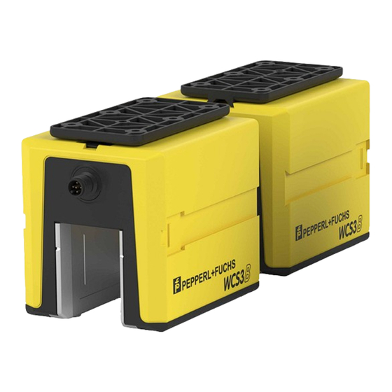
Two read heads (hereinafter referred to as safeWCS/PUS) are connected in the opposed mounting position on a safe PUS-F161-B**-WCS evaluation unit (hereinafter referred to as PUS evaluation unit) in the WCS3B-LS221-U* series. The PUS-F161-B**-WCS safe evaluation unit generates a safe position by comparing the two diverse position signals of the read heads. -
Page 9: Mounting System
Position encoding systemWCS3B-LS221-U*safeWCS/PUS read heads Product Description Mounting System There are three different mounting systems available for mounting the code rail. The bracket system, the WCS3 aluminum profile system, and the WCS2 aluminum profile system with fix- ture for a guide trolley. The three mounting systems can be screwed directly to the surface or mounted on standard C profile rails. -
Page 10: Read Head
Position encoding systemWCS3B-LS221-U*safeWCS/PUS read heads Product Description Read Head 3.3.1 Introduction The enclosure of the read head is made from robust plastic and has degree of protection (IP54). The mounting base for securing the read head is included in the scope of delivery. On the inside of the read head there are easily removable, transparent plastic lenses that protect the reading area against dirt and damage. -
Page 11: Overview
Position encoding systemWCS3B-LS221-U*safeWCS/PUS read heads Product Description 3.3.2 Overview safeWCS/PUS safeWCS/PUS read heads have a gap width of 31 mm. This allows greater tolerance when mounting the read head and aligning it with the code rail. safeWCS/PUS systems are suitable for monitoring conveyor belts, automated storage and lifting systems. -
Page 12: Tolerances
Position encoding systemWCS3B-LS221-U*safeWCS/PUS read heads Product Description 3.3.3 Tolerances Tolerance for Y and Z axis Figure 3.3 Tolerance for Y and Z axis Read head tolerances safeWCS/PUS safeWCS/PUS-Outdoor Y axis ± 15.5 mm ± 12 mm Z axis ± 14 mm ±... - Page 13 Position encoding systemWCS3B-LS221-U*safeWCS/PUS read heads Product Description Tolerance for inclined position Figure 3.5 Tolerance for inclined position Read head tolerances safeWCS/PUS safeWCS/PUS-Outdoor ±5° ±4° Tolerance of inclined position with 2 safeWCS/PUS read heads Figure 3.6 Tolerance for inclined position Read head tolerances safeWCS/PUS ±1°...
-
Page 14: Code Rail
Position encoding systemWCS3B-LS221-U*safeWCS/PUS read heads Product Description Code Rail 3.4.1 Introduction The absolute code rail is different for the WCS2 system and the WCS3 system. Therefore, the code rail cannot be swapped between the two systems. For WCS3, the height of the code rail is always 70 mm;... - Page 15 Position encoding systemWCS3B-LS221-U*safeWCS/PUS read heads Product Description Product name Description WCS3-CS70-L1 Laminate, hole 1 WCS3-CS70-M1 Stainless steel, hole 1 WCS3-CS70-L0 Laminate, no hole WCS3-CS70-L2 Laminate, Vahle VKS hole...
-
Page 16: Transport And Storage
Position encoding systemWCS3B-LS221-U*safeWCS/PUS read heads Transport and Storage Transport and Storage Retain the original packaging. Always store or transport the device in the original packaging to protect it from electrostatic discharge (ESD) and mechanical damage. -
Page 17: Mounting The Read Head
Position encoding systemWCS3B-LS221-U*safeWCS/PUS read heads Mounting the Read Head Mounting the Read Head Installing the mounting base and connecting plate The read heads are supplied with two special mounting bases and a connecting plate. The mounting bases must be attached to the read heads. On three sides of the read head enclo- sure, dovetail grooves are integrated with a quick release lock. - Page 18 Position encoding systemWCS3B-LS221-U*safeWCS/PUS read heads Mounting the Read Head Connecting plate dimensions ø 8.6 (8x) ø 4.5 (4x) Mounting base dimensions Note The mounting bases are fitted with press-in nuts so that they can be screwed to the connection plate. M4 (6x) 12.5 ø...
- Page 19 Position encoding systemWCS3B-LS221-U*safeWCS/PUS read heads Mounting the Read Head Note Mounting Position WCS3B-LS221-U1 WCS3B-LS221-U2 314.573 m Figure 5.2 Mounting Position Mount the two read heads so that the read head WCS3B-LS221-U1 points in the direction of travel (counting the position direction upward) and the read head WCS3B-LS221-U2 points in the opposite direction of travel (counting the position direction downward) on the code rail and the electrical connector plugs of the two read heads point to each other.
-
Page 20: Replacing Plastic Lenses
Position encoding systemWCS3B-LS221-U*safeWCS/PUS read heads Mounting the Read Head Mount and remove the mounting bases and the connecting plate Slide the dovetail groove on the read head onto the guide rail of the mounting base. In the end position, the spring tongue engages audibly in the quick release lock. Secure the mounting base to the connecting plate with screws. -
Page 21: Retrofitting The Outdoor Protective Enclosure
Position encoding systemWCS3B-LS221-U*safeWCS/PUS read heads Mounting the Read Head Retrofitting the Outdoor Protective Enclosure The enclosure can be retrofitted to the safeWCS/PUS read heads using RS-485, SSI, and CANopen interfaces. Read heads with EtherNet/IP and PROFINET interface can only be used as pre-assembled devices. - Page 22 Position encoding systemWCS3B-LS221-U*safeWCS/PUS read heads Mounting the Read Head Press the socket onto the connector bracket by hand. Figure 5.6 Attaching the mounting base Secure the mounting base to the protective lid with four self-tapping screws (galvanized). The maximum tightening torque is 0.7 Nm. Loosen the two fixing screws of the connector bracket by half a revolution each to move the bracket.
-
Page 23: Ordering Information
Position encoding systemWCS3B-LS221-U*safeWCS/PUS read heads Mounting the Read Head Tighten the pressure relief plugs in the opposite end of the protective lid using the special tool. If you have mounted the protective enclosure completely, you will still be able to see the status LEDs on the front of the enclosure. -
Page 24: Mounting The Outdoor Protective Enclosure
Position encoding systemWCS3B-LS221-U*safeWCS/PUS read heads Mounting the Read Head Mounting the Outdoor Protective Enclosure Warning! Improper mounting Risk of injury if mounted improperly • Ensure you have sufficient space before starting work. • Take care when using sharp-edged components and always wear safety gloves. •... - Page 25 Position encoding systemWCS3B-LS221-U*safeWCS/PUS read heads Mounting the Read Head Mounting and Dismounting the Outdoor Protective Enclosure Attach the outdoor protective enclosure to your plant using M6 screws (1). The maximum torque is 6 Nm. Note We recommend using corrosion-resistant stainless steel screws (A2/8.8). Connect the connector plug to the socket of the outdoor protection enclosure.
-
Page 26: Mounting The Code Rail
Position encoding systemWCS3B-LS221-U*safeWCS/PUS read heads Mounting the Code Rail Mounting the Code Rail Introduction With continuous position measurement for a route, you have to mount the code rail in one piece. Depending on the operational conditions, there are various options for securing the code rail: •... -
Page 27: Installation Notes
Position encoding systemWCS3B-LS221-U*safeWCS/PUS read heads Mounting the Code Rail Installation Notes Mounting Position The mounting position of the code rail is arbitrary. When mounting the code rail, make sure that all mounting brackets and rail holders of the profile system are at one level. The surface on which the mounting brackets and rail holders are mounted must be level. -
Page 28: Mounting The Code Rail On A Straight Route
Position encoding systemWCS3B-LS221-U*safeWCS/PUS read heads Mounting the Code Rail 6.2.1 Mounting the Code Rail on a Straight Route Mounting the Code Rail—Straight Route Mount the mounting brackets at an offset of max. 1.25 m along the route on the substructure. Align the mounting brackets. -
Page 29: Mounting In Horizontal Curves
Position encoding systemWCS3B-LS221-U*safeWCS/PUS read heads Mounting the Code Rail 6.2.2 Mounting in Horizontal Curves A horizontal curve is a curve to the left/right. The wide read head gap on the safeWCS/PUS read head permits minimum curve radii of 300 mm in conjunction with the mounting bracket system. - Page 30 Position encoding systemWCS3B-LS221-U*safeWCS/PUS read heads Mounting the Code Rail Mounting the Code Rail—Curve Mount the curve brackets tangentially along the bend of the arc or curve at an offset of max. 0.7 Cut the WCS-SP2 stabilizing profile to the length of the arc or curve. Insert the stabilizing profile into the curve bracket.
-
Page 31: Mounting In Vertical Curves
Position encoding systemWCS3B-LS221-U*safeWCS/PUS read heads Mounting the Code Rail Note Circular Path Note the following special feature for a closed section (circular path, oval, etc.): Due to how the WCS works, you cannot route the code rail continuously along the entire circumference of the circle. -
Page 32: Interruptions In The Profile Rail
Position encoding systemWCS3B-LS221-U*safeWCS/PUS read heads Mounting the Code Rail Figure 6.5 Cutting the code rail Insert the code rail into the aluminum profile together with the fixing cord. Secure the code rail with the fixing cord in the aluminum profile rail using the mounting tool (see chapter 6.4.5). 6.2.4 Interruptions in the Profile Rail In some applications, it is necessary to interrupt the course of the code rail, e.g., for crane... - Page 33 Position encoding systemWCS3B-LS221-U*safeWCS/PUS read heads Mounting the Code Rail Example In principle, branches of multiple segments or track switches can also be realized with WCS. Make sure that there is a minimum distance of 85 mm between the code rail segments. Figure 6.7 Overhead conveyor example...
-
Page 34: Mounting The Code Rail With Mounting Brackets
Position encoding systemWCS3B-LS221-U*safeWCS/PUS read heads Mounting the Code Rail Mounting the Code Rail with Mounting Brackets 6.3.1 Introduction The bracket system is an easy way to mount laminate or stainless steel code rails. It consists of brackets for routing the code rail in straight sections, as well as brackets for routing the code rail in curves and circular paths. - Page 35 Position encoding systemWCS3B-LS221-U*safeWCS/PUS read heads Mounting the Code Rail Mounting Bracket for Straight Routing M6 x 12 M6 x 12 M6 x 12 M6 x 12 WCS-MB1/WCS-MB1-C WCS-MB2/WCS-MB2-C Screw connection with M6 screws Screw connection with C groove The brackets are made from galvanized sheet steel and are supplied pre-assembled. Various versions of the mounting brackets for installation of the code rail are available: Product name Description...
- Page 36 Position encoding systemWCS3B-LS221-U*safeWCS/PUS read heads Mounting the Code Rail Product name Description Product photo WCS-MB-C Bracket for straight sections Powder-coated WCS-MB2-C Powder-coated bracket for straight sections With C T-slot nut Note The recommended support distance for straight section elements is at least one bracket every 1.25 m.
- Page 37 Position encoding systemWCS3B-LS221-U*safeWCS/PUS read heads Mounting the Code Rail Mounting Bracket for Curves or Circular Paths M4 x 12 3.5 x 6.5 M6 x 20 M4 x 12 3.5 x 6.2 WCS-MB-B WCS-MB2-B Screw connection with M6 screws available Screw connection with C groove Product name Description Product photo...
- Page 38 Position encoding systemWCS3B-LS221-U*safeWCS/PUS read heads Mounting the Code Rail Product name Description Product photo WCS-MB1-B-C Bracket for curves With M6 screw connection and powder coating WCS-MB2-B-C Powder-coated bracket for curves With C T-slot nut WCS-SP2 Stabilizing profile For curved sections Note The recommended support distance for curves is at least one bracket every 0.5 m.
-
Page 39: Attaching The Tensioning Device
Position encoding systemWCS3B-LS221-U*safeWCS/PUS read heads Mounting the Code Rail 6.3.3 Attaching the Tensioning Device Using the tensioning device prevents the stainless steel code rail from warping due to tempera- ture fluctuations after mounting. It also makes mounting easier. Note Pretensioning of the stainless steel code rail is not necessary for system function. Pretensioning is useful only if large temperature fluctuations can occur within a short time. -
Page 40: Assembly Of The Wcs3 Aluminum Profile System
Position encoding systemWCS3B-LS221-U*safeWCS/PUS read heads Mounting the Code Rail Assembly of the WCS3 aluminum profile system 6.4.1 Introduction A special aluminum profile system has been developed for quick mounting of the 70 mm WCS3 code rail made from plastic laminate or stainless steel. The aluminum profile is designed such that it supports the code rail. - Page 41 Position encoding systemWCS3B-LS221-U*safeWCS/PUS read heads Mounting the Code Rail Item Designation Product name Note Aluminum profile rail WCS3-PS1* Length: 2 m/6 m Code Rail WCS3-CS70-* Stainless steel, laminated Read head WCS3B-LS** Mounting base 7 and 8 Vehicle fixture Butt connector WCS3-MC1 Mounting tool for fixing WCS3-FT1...
- Page 42 Position encoding systemWCS3B-LS221-U*safeWCS/PUS read heads Mounting the Code Rail Rail Holder Overview Figure 6.11 Overview Item Designation Product name Rail holder WCS3-MH Rail holder with screw connection WCS3-MH1 Rail holder with screw connection for C profile rails WCS3-MH2 Note Support distance for perpendicular/suspended mounting: < 2.5 m. Support distance for lateral mounting: <...
-
Page 43: Rail Holder
Position encoding systemWCS3B-LS221-U*safeWCS/PUS read heads Mounting the Code Rail 6.4.3 Rail Holder Mounting the Rail Holders Mount the rail holders at an offset of 2 m along the route on the substructure for a lateral mounting and 2.5 m for a perpendicular or suspended mounting. Align the rail holders along a taut cord. -
Page 44: Butt Connectors For Profile Rails
Position encoding systemWCS3B-LS221-U*safeWCS/PUS read heads Mounting the Code Rail 6.4.4 Butt Connectors for Profile Rails Butt connectors are required for connecting aluminum profile rails. The WCS3-MC1 butt con- nector consists of a 170 mm long extruded aluminum profile and two self-tapping screws. Designation Part number Function/use... - Page 45 Position encoding systemWCS3B-LS221-U*safeWCS/PUS read heads Mounting the Code Rail Slide the profile rails together with the butt connectors. Note When you slide the aluminum profile rails together with the butt connectors, make sure there is a gap to compensate for thermal expansion. A gap is necessary if the maximum possible operating temperature is greater than the temperature during the assembly.
-
Page 46: Mounting The Code Rail
Position encoding systemWCS3B-LS221-U*safeWCS/PUS read heads Mounting the Code Rail 6.4.5 Mounting the Code Rail Mounting the Code Rail in the Profile Rail Insert the code rail into the groove of the profile rail. Figure 6.13 Mounting the code rail Fix the code rail in place by pressing the plastic fixing cord into the groove of the profile rail and simultaneously pressing on the code rail. - Page 47 Position encoding systemWCS3B-LS221-U*safeWCS/PUS read heads Mounting the Code Rail Mounting Tool (WCS3-FT1) A special mounting tool is available for fixing the code rail in place securely and quickly. The mounting tool is recommended if the aluminum profile system is installed suspended. The tool consists of a housing with casters, similar to the guide trolley.
-
Page 48: Fixed Points
Position encoding systemWCS3B-LS221-U*safeWCS/PUS read heads Mounting the Code Rail 6.4.6 Fixed Points To prevent the aluminum profile rails slipping in the rail holders when mounted horizontally, the profile must be securely connected to the substructure. Positioning a Fixed Point Position a fixed point in the middle of the section that you want to fix in place. Pierce the rail holder on both sides with a metal drill with 1.8 mm diameter. - Page 49 Position encoding systemWCS3B-LS221-U*safeWCS/PUS read heads Mounting the Code Rail Figure 6.16 Connection between the rail holder and the aluminum profile We recommend that you fix the aluminum profile in place at multiple points along a route using the method described. Make sure that there are sufficient expansion gaps between the aluminum profiles (see chapter 6.4.4).
-
Page 50: Suspended Mounting With Stainless Steel Code Rail
Position encoding systemWCS3B-LS221-U*safeWCS/PUS read heads Mounting the Code Rail 6.4.7 Suspended Mounting with Stainless Steel Code Rail If you want to mount the stainless steel code rail suspended, you have to secure the code rail against falling down. This applies in particular when there are frequent changes in temperature. For lengths up to 25 m, using the tensioning device (see chapter 6.3.3) is sufficient. -
Page 51: Grounding The Aluminum Profile System
Position encoding systemWCS3B-LS221-U*safeWCS/PUS read heads Mounting the Code Rail Figure 6.18 Screwing in a self-tapping screw 6.4.8 Grounding the Aluminum Profile System Connect the aluminum profile with the plant potential at low resistance at least every 30 m. Figure 6.19 Grounding... -
Page 52: Assembly Of The Wcs2 Aluminum Profile System
Position encoding systemWCS3B-LS221-U*safeWCS/PUS read heads Mounting the Code Rail Assembly of the WCS2 aluminum profile system 6.5.1 Introduction A profile rail system with WCS guide trolley has been developed for applications where the moving carriage has high mechanical tolerances. The guide trolley safeguards the optimal position of the read head in relation to the code rail at all times and compensates for running tolerances between the vehicle and the WCS system. - Page 53 Position encoding systemWCS3B-LS221-U*safeWCS/PUS read heads Mounting the Code Rail Item Designation Product name Note Fixing cord WCS-MF1 safeWCS/PUS-Outdoor WCS3B-LS*-O* Read head with outdoor protec- tive enclosure Guide trolley WCS3-GT09-P1-O Aluminum profile rail WCS2-PS1(-C) 2.5 m or 5 m long, optional (-C: powder-coated) Rail holder WCS2-MH*...
- Page 54 Position encoding systemWCS3B-LS221-U*safeWCS/PUS read heads Mounting the Code Rail Rail Holder Overview Figure 6.22 Overview Item Designation Product name Rail holder WCS2-MH Rail holder with screw connection WCS2-MH1 Rail holder with screw connection for C profile rails WCS2-MH2...
-
Page 55: Rail Holder
Position encoding systemWCS3B-LS221-U*safeWCS/PUS read heads Mounting the Code Rail 6.5.3 Rail Holder Mounting the Rail Holders Mount the rail holders at intervals of 1.5 m along the route on the substructure for a perpendicular or suspended mounting. Note For lateral mounting with a WCS2 guide trolley, the support distance must be reduced to 1.25 m. -
Page 56: Butt Connectors For Profile Rails
Position encoding systemWCS3B-LS221-U*safeWCS/PUS read heads Mounting the Code Rail 6.5.4 Butt Connectors for Profile Rails Butt connectors are required for connecting aluminum profile rails. The WCS2-MC* butt con- nector consists of two flat pieces and four self-tapping screws. 45.0 Figure 6.24 WCS2-MC1/WCS2-MC2 Designation Part number... - Page 57 Position encoding systemWCS3B-LS221-U*safeWCS/PUS read heads Mounting the Code Rail Mounting the Butt Connector Slide the two flat pieces into the bottom grooves of the two profile rails that you want to connect. Push the end of the connector that has the holes in first. Screw the self-tapping screws into the 1.8 mm diameter holes in the flat pieces.
- Page 58 Position encoding systemWCS3B-LS221-U*safeWCS/PUS read heads Mounting the Code Rail Note When you slide the aluminum profile rails together with the butt connectors, make sure there is a gap to compensate for thermal expansion. A gap is necessary if the maximum possible operating temperature is greater than the temperature during the assembly.
-
Page 59: Mounting The Code Rail
Position encoding systemWCS3B-LS221-U*safeWCS/PUS read heads Mounting the Code Rail 6.5.5 Mounting the Code Rail Mounting the Code Rail in the Profile Rail Insert the code rail into the groove of the profile rail. Fix the code rail in place by pressing the plastic fixing cord into the groove of the profile rail and simultaneously pressing on the code rail. -
Page 60: Mounting Tool
Position encoding systemWCS3B-LS221-U*safeWCS/PUS read heads Mounting the Code Rail Mounting Tool A special mounting tool is available for fixing the code rail in place securely and quickly. The mounting tool is recommended if the aluminum profile system is installed suspended. The tool consists of a housing with casters, similar to the guide trolley. -
Page 61: Fixed Points
Position encoding systemWCS3B-LS221-U*safeWCS/PUS read heads Mounting the Code Rail 6.5.6 Fixed Points When the rails are mounted horizontally, a locking bracket is required to prevent the aluminum profile rails slipping in the rail holders. Designation Part number Function/use Material WCS2-LB1 184048 Locking bracket for aluminum Sheet steel, galvanized... -
Page 62: Guide Trolley For The Safewcs/Pus-Outdoor Read Head With Protective Enclosure
Position encoding systemWCS3B-LS221-U*safeWCS/PUS read heads Mounting the Code Rail Figure 6.26 Code rail fixed point 6.5.7 Guide Trolley for the safeWCS/PUS-Outdoor Read Head with Protective Enclosure The protective enclosure with the read head is mounted in the guide trolley (WCS3-GT09-P1- O). -
Page 63: Grounding The Aluminum Profile System
Position encoding systemWCS3B-LS221-U*safeWCS/PUS read heads Mounting the Code Rail Mounting the Protective Enclosure with the Read Head in the Guide Trolley 90 mm ø 8 mm Figure 6.28 Guide trolley with protective enclosure Slide the protective enclosure into the guide trolley from above so that the mounting holes on the guide trolley align correctly with the threaded holes on the protective enclosure. -
Page 64: Commissioning
The counterpart of the plug connections, the 5-pin M12 socket, is not included in the scope of delivery for the read head. You can obtain suitable connectors and cables from Pepperl+Fuchs, Connecting the safeWCS/PUS read heads to the PUS evaluation unit This chapter describes the setup of the safeWCS/PUS system in simplified form. - Page 65 Position encoding systemWCS3B-LS221-U*safeWCS/PUS read heads Commissioning Connecting the read heads PUS-F161-B31-WCS X35-1 X35-2 WCS3B-LS221-U2 WCS3B-LS221-U1 Figure 7.2 Connect the WCS3B-LS221-U1 read head (position direction counting upward) to the PUS evaluation unit at plug X35-1. Connect the WCS3B-LS221-U2 read head (position direction counting downward) to the PUS evaluation unit at plug X35-2.
- Page 66 Position encoding systemWCS3B-LS221-U*safeWCS/PUS read heads Commissioning Connection assignment of safeWCS/PUS read heads to the PUS evaluation unit The PUS evaluation unit has two separate RS485 interfaces. The two read heads have a fixed assignment to the relevant inputs: Connect the WCS*U1 read head to X35-1 (upper plug) Connect the WCS*U2 read head to X35-2 (lower plug) Shielded cables and shielded plugs must be used.
- Page 67 Position encoding systemWCS3B-LS221-U*safeWCS/PUS read heads Commissioning Figure 7.4 PUS evaluation unit M12 plug, 8-pin 5-pin M12 socket safeWCS/PUS read heads Note Shielded twisted-pair cables and plugs with grounding must be used. Cable Description Field-attachable cable V1-G-BK5M-PURO2/ Bus cable DeviceNet/CANopen M12 socket straight A-coded 4-pin to CAN-V19-G-Y70 M12 plug straight A-coded 8-pin, PUR cable 4-wire twisted pair black, shielded, UL-approved, suitable for drag chains, outdoor...
-
Page 68: Position Direction
Position encoding systemWCS3B-LS221-U*safeWCS/PUS read heads Commissioning Position direction The WCS3B-LS221-U1 read head is mounted on the code rail in the direction of travel (count- ing the position direction upward) and the WCS3B-LS221-U2 read head is mounted on the code rail opposite to the direction of travel (counting the position direction downward). Position direction of WCS3B-LS221-U1 read head (counting upward) The front WCS3B-LS221-U1 read head has the same position direction and behavior as a standard WCS3B read head:... -
Page 69: Data Protocols
Position encoding systemWCS3B-LS221-U*safeWCS/PUS read heads Commissioning Data Protocols A data protocol is available for the direct connection of the read head to the higher-level con- troller using a serial communication channel. A byte has the following format: Start Stop Figure 7.5 Data structure In the data protocol, the 8th data bit is used to distinguish between request bytes and response bytes. - Page 70 Position encoding systemWCS3B-LS221-U*safeWCS/PUS read heads Commissioning Description of the protocol data Activation of the read head Read head address Read head address 0 Read head address 1 Read head address 2 Read head address 3 Send position value Send diagnostic result Data from the read head Function number for the read head F0=0 (send position value) State of the...
- Page 71 Position encoding systemWCS3B-LS221-U*safeWCS/PUS read heads Commissioning Diagnostic function F0=1 The read head can be requested to perform a diagnosis of the photoelectrics via the request byte to the read head. For this purpose, the read head must be located outside the code rail. The level of contamination on the optical unit is detected automatically during operation and the diagnostic bit (DB) is set if the contamination is too high.
- Page 72 Position encoding systemWCS3B-LS221-U*safeWCS/PUS read heads Commissioning Result of the check Remedy The upper edge of the code rail is outside the • Align the code rail precisely tolerance range of the read head • Aligning the read head • Use the guide system for the read head The plastic lenses on the optical unit are dirty •...
-
Page 73: Status And Error Messages
Position encoding systemWCS3B-LS221-U*safeWCS/PUS read heads Commissioning Status and Error Messages Error number Cause Remedy WCS read head cannot calculate posi- tion value because: Optical unit is dirty Clean optical unit Plastic protective lenses are scratched Align WCS read head and code rail cor- rectly;... -
Page 74: Led Status Indicator
Position encoding systemWCS3B-LS221-U*safeWCS/PUS read heads Commissioning LED status indicator Description of the LED Indicators Item Display Designation Color Display Meaning Operation Indica- Green Power on Data flow indicator Yellow Data transfer active Fault Indicator System error Flashing Read head out- side the code rail 2 and 3 STS and COM Contamination... -
Page 75: Maintenance
Position encoding systemWCS3B-LS221-U*safeWCS/PUS read heads Maintenance Maintenance Danger! Danger to life due to electrical current! Contact with live parts causes immediate danger to life. • Allow only qualified electricians to carry out work on the electrical installation. • Switch off the voltage supply before carrying out servicing, cleaning, and repairs, and pre- vent the supply from being switched on again. -
Page 76: Repairs
Damage to the Code Rail For high-quality and lasting results, the use of original Pepperl+Fuchs code rails is recom- mended. The procedure for replacing damaged code rail sections is described below. -
Page 77: Wcs Stainless Steel Code Rail (Mounting Bracket System)
Position encoding systemWCS3B-LS221-U*safeWCS/PUS read heads Maintenance Weld the two code rails to each other at four points, e.g., using shielding gas welding equipment. Note Alternatively, you can connect the code rails using blind rivets. Blind rivets can be used only on the upper edges of the code rails because they do not fit in the V-groove of the aluminum profile. -
Page 78: Wcs Laminate Code Rail (Aluminum Profile)
Position encoding systemWCS3B-LS221-U*safeWCS/PUS read heads Maintenance To prevent the code rails slipping against each other, securely fasten overlapping sections in place (e.g., using a screw clamp). Weld the two code rails to each other at four points, e.g., using shielding gas welding equipment. -
Page 79: Wcs Laminate Code Rail (Mounting Bracket System)
Position encoding systemWCS3B-LS221-U*safeWCS/PUS read heads Maintenance Hold the overlapping code rails firmly to prevent them from shifting. Punch four holes with a diameter of 3 mm through the two code rail sections using a punch as shown in the figure. Insert the hollow rivets from the reparation set in the holes;... - Page 80 Position encoding systemWCS3B-LS221-U*safeWCS/PUS read heads Maintenance Note The "old" and "new" (replacement) code rails must each overlap by around 10 cm to ensure that the hole pattern of the two rail sections align correctly. Larger overhangs are cut off. Hold the overlapping code rails firmly to prevent them from shifting. Punch four holes with a diameter of 3 mm through the two code rail sections using a punch as shown in the figure.
-
Page 81: Disposal
Position encoding systemWCS3B-LS221-U*safeWCS/PUS read heads Disposal Disposal The device, built-in components, packaging, and any batteries contained within must be disposed in compliance with the applicable laws and guidelines of the respective country. - Page 82 Pepperl+Fuchs Quality Download our latest policy here: www.pepperl-fuchs.com/quality www.pepperl-fuchs.com © Pepperl+Fuchs · Subject to modifications / DOCT-7743...
Need help?
Do you have a question about the WCS3B-LS221-U and is the answer not in the manual?
Questions and answers