Table of Contents
Advertisement
Quick Links
Advertisement
Table of Contents

Related Manuals for Pepperl+Fuchs 6500


Summary of Contents for Pepperl+Fuchs 6500
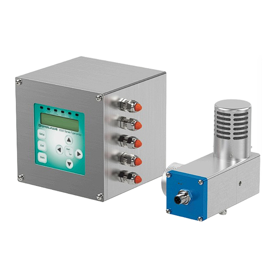
- Page 1 6500 Purge System User Manual Type Ex px Purge and Pressurization System...
- Page 2 Phone: +49 621 776 - 0 E-mail: info@de.pepperl-fuchs.com North American Headquarters Pepperl+Fuchs Inc. 1600 Enterprise Parkway Twinsburg, Ohio 44087 Phone: +1 330 425-3555 E-mail: sales@us.pepperl-fuchs.com Asia Headquarters Pepperl+Fuchs Pte. Ltd. P+F Building 18 Ayer Rajah Crescent Singapore 139942 Phone: +65 6779-9091 E-mail: sales@sg.pepperl-fuchs.com https://www.pepperl-fuchs.com...
-
Page 3: Table Of Contents
2.3.2 Electrical connections ................18 2.3.3 Dimensions .................... 20 2.4. Mounting of the control unit ................. 24 2.5. EPV-6500 pressure relief vent ..............27 2.5.1 Technical Data: Vent ................28 2.5.2 Electrical connections ................30 2.6. Dimensions ....................31 2.6.1 Flow rate curves ..................32 2.7. - Page 4 6500 S T erieS anual able of conTenTS 3.2. Before Setup ....................41 3.2.1 Setup procedures for standard applications ........... 43 3.3. Operation for standard applications ............44 3.4. Sequence of Events ..................45 3.4.1 Energizing enclosure power ..............45 3.4.2 De-energizing enclosure power ..............
-
Page 5: Introduction
6500 series purge and pressurization system. These operating instructions contain important data and information to ensure the safe use of the 6500 system in hazardous areas and to meet the requirements of Directive 2014/34/EU. This manual, particularly the safety information, must be followed by all personnel who work on the system. -
Page 6: Target Group, Personnel
Additional documents 1.2. Target group, Personnel Responsibility for planning, assembly, commissioning, operation, maintenance, and dismounting of the 6500 series lies with the plant operator. Personnel working on this system must: be familiar with the occupational safety and accident prevention regulations and have been briefed regarding handling of the unit. -
Page 7: Symbols Used
6500 S i erieS anual nTroducTion 1.3. Symbols Used This document contains symbols to identify warning messages and information messages. Warnings You will always find warning messages whenever hazards could result from your actions. It is essential that you observe these warning messages to ensure your personal safety and to prevent property damage. -
Page 8: Pertinent Laws, Standards, Directives, And Further Documentation
A Declaration of Conformity is included with these instructions and can be requested from the manufacturer or obtained online at www.pepperl-fuchs.com. Additional documentation can also be provided for individual components. The product manufacturer, the Pepperl+Fuchs Group, 68307 Mannheim, has a certified quality assurance system that conforms to ISO 9001. ISO9001... -
Page 9: Product Description
Note EN 60079-2 and IEC 60079-2 do not cover both gas- and dust-hazardous atmospheres. The 6500 system provides a solution for both at the same time but this must be evaluated by the certification bodies for approval. -
Page 10: 6500 System Overview
Zone 1/21 hazardous area to achieve an Ex px rating, or Zone 2/22 rated equipment mounted in an enclosure in a Zone 1/21 hazardous area to achieve an Ex py rating. The 6500 control unit and EPV-6500 vent is certified for Ex px or Ex py applications. -
Page 11: System Components
It is intrinsically safe and has a needle valve for adjusting the pressure in the enclosure during the pressurization phase. WArNINg! When using other customer-provided electrical valves, please follow the entity parameters of the valve and the output of the 6500 control unit. -
Page 12: 6500 Control Unit
The 6500 control unit is the control center of the pressurized system and is suitable for Zone 1 and 21, Ex pxb and Ex pyb applications. The 6500 control unit can be ordered for different mounting configurations for different applications. This unit does not come with cable glands, which allows customers to select the type or brand of cable glands to use, but they must be approved for the area and application. -
Page 13: Technical Data: Control Unit
The features of the 6500 control unit are: User-selectable for pxb or pyb applications User-interface is intrinsically safe touch that can be ordered for remote mounting Universal power requirement, 20 ... 30 VDC / 100 ... 240 VAC... - Page 14 P erieS anual roducT eScriPTion 4-pin micro connector and cable (provided) For the 6500-01-PM02, cable length is 5 meters. Input type Intrinsically safe, maximum cable 60 meters at 50 pf/ft and 0.2µH/ft Inputs Input I Voltage-free contact or namur proximity sensor...
- Page 15 Protective gas supply Instrument grade air or inert gas Pressure requirement For 6500-MAN-DV: 1.4 to 8.3 bar (20 to 120 psig) For 6500-MAN-PV: 3.5 to 6.9 bar (50 to 1000 psig) Note: Max pressure will depend on the vent model used.
- Page 16 Hardware 316L stainless steel Mass Approximately 5.0 kg (11.0 lbs) Cable gland requirements For the 6500-CBLG requirements, please see data sheets available at www.pepperl-fuchs.com I.S. cable glands Requires (5) M12 approved cable glands (See accessories section for approved cable glands.)
- Page 17 6500 S P erieS anual roducT eScriPTion 2 conductors with same cross section, 0.2 mm² / 0.75 mm² stranded min/max 2 conductors with same cross section, 0.25 mm² / 0.34 mm² stranded, ferrules without plastic sleeve min/max WArNINg! The intrinsic safety entities listed in the table above are subject to the following considerations.
-
Page 18: Electrical Connections
6500 S P erieS anual roducT eScriPTion 2.3.2 electrical connections 6500 control unit terminal housing... - Page 19 Male receptacle on UIC user interface (Mating cable is included with 6500 control unit.) Note UIC connections are only to be connected to 6500-01-UIC_XX type user interface controller. Note Grounding points (internal and external) will be identified with a ground symbol.
-
Page 20: Dimensions
6500 S P erieS anual roducT eScriPTion 2.3.3 Dimensions 6500-01-eXT1-PNO-LNO external mount Dimension shown in mm (in). - Page 21 6500 S P erieS anual roducT eScriPTion 6500-01-PM01-PNO-LNO Internal mount with UIC attached to ePCU Dimension shown in mm (in).
- Page 22 6500 S P erieS anual roducT eScriPTion 6500-01-PM02-PNO-LNO Internal mount with UIC remote panel mount Dimension shown in mm (in).
- Page 23 6500 S P erieS anual roducT eScriPTion 6500-01-PM02-PNO-LNO Internal mount with UIC remote panel mount (cont’d) Dimension shown in mm (in).
-
Page 24: Mounting Of The Control Unit
6500 S P erieS anual roducT eScriPTion 2.4. Mounting of the control unit Control unit flush mount Intrinsically Safe Wiring I.S. / Non-I.S. Partition Intrinsically Safe Wiring 6 mm screw text DANger! Display can be rotated ± 90° as shown. Rotation of display is not permissable when the I.S. - Page 25 6500 S P erieS anual roducT eScriPTion UIC mounting: Side mount Vent cap (included) EPV-6500 Seal gasket (included) Locking nut with grounding screw (included) DANger! Unused cable entries will require a properly rated hazloc plug. UIC mounting: Top mount Test_side mount 12.2.2016...
- Page 26 UIC mounting: PM01 internal mount UIC mounting: PM02 component kit WArNINg! When mounting the 6500 control unit to a wall, the mounting method should be sturdy enough to support 4 times the gross weight of the 6500 control unit.
-
Page 27: Epv-6500 Pressure Relief Vent
‘-01’ model, the back pressure during purging will be higher; however, the leakage rate for pressurization is lower. • EPV-6500-__-05: Gives the best seal for pressurization but highest back pressure for purging. These vents are extremely useful for bottled gas applications. -
Page 28: Technical Data: Vent
The flow is measured across this 8 mm orifice plate for greater accuracy. When used with a proportional valve, like the 6500-MAN-PV, the control of flow is between 17 l/min (0.6 scfm) and 85 l/min (3 scfm). - Page 29 EPV-6500-__-05 3.8 mbar (1.5 in wc) EPV-6500-__-07 EPV-6500-__-08 Accuracy Pressure reading EPV-6500-__-01, 03, 05, 07, 08 At 25 °C ± 0.025 mbar (± 0.01 in wc) Full temperature range ± 0.125 mbar (± 0.05 in wc) Flow reading EPV-6500-__-01, 03, 05 Standard vent, ±...
-
Page 30: Electrical Connections
1½” NPT knockout (50.8 mm (2”) hole) with seal nut included 2.5.2 electrical connections '+' Brown 'A' White 'B' Black '-' Blue Male receptacle on EPV-6500 vent (mating cable included with EPV-6500 vent) Note Vent connections are only to be connected to EPV-6500-XX-XX type vent. -
Page 31: Dimensions
6500 S P erieS anual roducT eScriPTion 2.6. Dimensions The following dimensions are for all the standard and continuous EPV-6500 vents. 47.6 77.8 88.9 134.6 25.4 16.3 57.2 28.6 28.6 57.2 Dimension shown in mm (in). -
Page 32: Flow Rate Curves
They can be used for estimating purge time, but the actual purge time will be automatically calculated by the 6500 control vent. These graphs are used to determine which vent type will be best suited for the application. - Page 33 6500 S P erieS anual roducT eScriPTion ePV-6500-__-05: gives the best seal for pressurization, but highest back pressure for purging Enclosure press. vs flow EPV-6500-__-05 20.0 15.0 10.0 l/min Continuous vent pressure/flow curves The enclosure pressure vs. flow rate curves correspond to the EPV-6500-__-07, -08 vents.
- Page 34 6500 S P erieS anual roducT eScriPTion ePV-6500-__-08: The vent has a 16mm diameter opening and requires a continuous flow to maintain pressure/flow. Enclosure pressure vs. flow rate EPV-6500-__-08 16mm orifice mbar Mounting the ePV-6500 vent, inside and outside: external vent Internal vent...
-
Page 35: Manifold Valves
The 6500 system requires a purge/pressurization supply source. This flow/pressure is usually supplied by an electrical valve or manual valves. Pepperl+Fuchs offers optional valves for operation with the 6500 system for both standard applications (digital valves) and dilution applications (proportional valves). -
Page 36: Cable Glands (6500-Cblg
2.8. Cable glands (6500-CBLg...) The 6500 control unit does not come with cable glands. These can be supplied by the customer or can be purchased from Pepperl+Fuchs as a kit. Pepperl+Fuchs offers cable gland kits in several different materials for both the power side and the I.S. side entries. -
Page 37: Installation And Operation
PeraTion 3. Installation and Operation The 6500 control unit, EPV6500 vent, and manifold can be universally mounted to the customer’s enclosure to produce a certifiable system, configurable to either a “pyb” or “pxb” system. For “pyb” systems, all electrical equipment within the pressurized enclosure must be rated Zone 2 or 22, if applicable, and the enclosure contacts do not have to be de-energized when loss of pressure, but an alarm has to be activated. -
Page 38: For Dust Atmospheres
If the leakage rate is known, the 6500 system may be used to dilute the area or specific area within the enclosure to make other equipment safe to operate in the dilution area. - Page 39 ICA and dilutes the area so that the equipment can operate when the system is operating. WArNINg! For customer-supplied electrical valves, please consult the 6500 control unit entity parameters. Any equipment operating within the enclosure outside the dilution area would have to...
- Page 40 PeraTion For dilution to properly be applied, the 6500 system would have to use the continuous vent (EPV-6500-__-07 or 08) and a proportional valve like the 6500-MAN-PV. The continuous vent accurately measures the pressure and flow across an open orifice plate inside the vent to give flow vs.
-
Page 41: Before Setup
These factors also affect the over and under shoot of the proportional valve. Reaction times are dependent on the complete system and final adjustments may have to be made while the system is commissioned. 3.2. Before Setup When the 6500-01-* control unit is received, the humidity indicator card should be checked. - Page 42 6500 S i erieS anual nSTallaTion and PeraTion If the indicator card is reading 40 or 50, follow the instructions on the desiccant pack to recharge it. Once recharged, or if the indicator card is reading 30 or below upon receipt, proceed with commissioning the unit.
-
Page 43: Setup Procedures For Standard Applications
Define the 6500 system parameters in the menu structure for the application. Refer to “Programming Menu” section for instructions. Set the user interface on the 6500 control unit to pressure for indication of enclosure pressure. Turn on the protective gas supply. Set the regulator to its lowest setting and then gradually increase pressure. -
Page 44: Operation For Standard Applications
If the enclosure pressure drops below the minimum overpressure setpoint, then • action is required. For “pyb”, enclosure contacts can remain on, but an alarm must be initiated (this is done through the AUX contacts on the 6500 control unit). DANger! gas and combustible dust locations EN and IEC 60079-2 standards do not state these requirements. -
Page 45: Sequence Of Events
6500 S i erieS anual nSTallaTion and PeraTion 3.4. Sequence of events 3.4.1 energizing enclosure power Immediate shutdown OFF/disabled Purge Start Door timer secured progress Overload Enable Timer=0 timer OFF/disabled Temp < Max Lock 1 ON Press < Max unused Flow >... -
Page 46: Energizing Enclosure Power
6500 S i erieS anual nSTallaTion and PeraTion 3.4.2 De-energizing enclosure power Control power relay input Control power broken/shorted relay Immediate shutdown input Immediate broken/shorted shutdown Bypass Immediate Timer=0 Start Bypass shutdown Bypass timer Overload timer Input ON Enable... -
Page 47: Programming
Start/set: for menu entry selection Note To turn on the back light on the 6500 display, push the Right and Left arrow key at the same time. To turn it off, repeat. Note To change the contrast in the 6500 display, push the Up and Down arrow keys at the same time, then adjust the contrast to the desired value. - Page 48 6500 S P erieS anual rograMMing PrOgrAMMINg MeNU: SETUP — PASSWORD — PURGE SETTINGS (BUTTON) — UNITS — INPUT SETTINGS — OUTPUT SETTINGS — PASSWORDS — LANGUAGE — BYPASS CONTROL — BLUETOOTH SETTINGS — FACTORY RESTORE — BOOTLOADER MODE —...
- Page 49 6500 S P erieS anual rograMMing eNVIrONMeNT: User-defined. The hazardous area classification in which the pressurized enclosure will be located. GAS requires purging. DUST requires cleaning out the enclosure before powering. Both require cleaning out the enclosure then purging before enclosure contacts are on.
- Page 50 User-defined. Determines the type of valve that will be used. DIGITAL: This controls the ‘DV’ output on the 6500 control unit and will activate a digital valve (solenoid valve) when purging, if the pressure as an input function is set up, if the temperature as an input is set up, or if an external input is set to trigger it.
- Page 51 6500 S P erieS anual rograMMing INPUT SeTTINgS: INPUT 1 — INPUT 1 FUNCTION — DISABLED — IMMEDIATE SHTDN — OVERLOAD — CONTROL PWR RELAY — CONTROL OUTPUT 1 — CONTROL VALVE — SYSTEM BYPASS — INPUT 1 SRM —...
- Page 52 6500 S P erieS anual rograMMing INPUT 1 FUNCTION: The input terminal on the 6500 control unit can be used to activate several functions as listed in the table below. FUNCTION ACTION DISABLeD Nothing happens when input is active...
- Page 53 6500 S P erieS anual rograMMing OFF DeLAY TIMe: If the digital valve is selected, this function will keep the digital valve on for the user-defined time after the off pressure is detected. Settings: 0 to 300 seconds Default: 0 seconds...
- Page 54 Default: NO PASSWOrDS: During the first power up of the 6500 control unit, the setup and bypass passwords are entered in by the user. These passwords can be changed at any time. The passwords are key strokes from the up, down, right, and left keys on the user-interface.
- Page 55 6500 S P erieS anual rograMMing LANgUAge: During the first power-up of the 6500 control unit, the language is selected and can be changed at any time. LANGUAGE — ENGLISH — SETTING CORRECT Y/N — DEUTSCH — SETTING CORRECT Y/N —...
- Page 56 PASSWORD — NO, YES To implement the factory restore, the bypass word is required. This will restore the 6500 system to the facgtory settings. After implementing a factory restore, the unit will request to enter setup and bypass passwords. BOOTLOADer LOAD SeTTINgS: BOOTLOADER MODE —...
-
Page 57: Statistics
5. Statistics Statistics Menu STATISTICS CURRENT ALARM LAST ALARM CURRENT FAULT LAST FAULT CLEAR STATISTICS CLEAR FAULT P+F 6500 REVISION SETTINGS Statistics TEMPERATURES MIN OVER PRESSURE MAX OVER PRESSURE MIN PURGE PRESSURE MAX PURGE PRESSURE LAST PURGE TIME MIN PURGE FLOW... - Page 58 Clear statistics CLEAR STATISTICS — NO, YES — SETTING CORRECT Y/N Clear fault CLEAR FAULT — NO, YES — SETTING CORRECT Y/N Pepperl+Fuchs 6500 revision P+F 6500 REVISION — MAIN UNIT — HARDWARE REVISION — X.XX — SOFTWARE REVISION — X.XX —...
- Page 59 6500 S S erieS anual TaTiSTicS Settings SETTINGS — ENCLOSURE VOLUME — NUMB OF EXCHANGES — VENT FLOW CONTROL — VALVE CONTROL — PURGE FLOW — DILUTION FLOW SP — MIN FLOW SP — ENVIRONMENT — MIN OVER PRESSURE —...
-
Page 60: Product Identification
In hazardous dust environment, the connector end of the vent shall be protected from direct exposure of a UV light source. See certificate for full information. Only EPV-6500-xx-xx vents can be connected to any certified 6500 control system. DANger! Non-observance of conditions of safe use will result in personal injury or death. -
Page 61: Applied Standards
Mounting EXT: For external mount 6500 control unit PM0: For panel or internal mount 6500 control unit User Interface Controller Device type 6500 Series vent Note 6500-01-UIC... comes with standard 6500-01 control unit. Nomenclature is only used when ordering replacements. -
Page 62: Markings (Labelling)
6500 S P erieS anual roducT denTificaTion ePV-6500 pressure relief vent E P V - 6 5 0 0 - A A - 0 1 Flow 01: High flow rate, low enclosure pressure, high leakage rate 03: Medium flow rate, medium enclosure pressure, medium leakage rate 05: Low flow rate, high enclosure pressure, low leakage rate 07: Continuous flow, 7 l/min to 85 l/min (0.6 to 3.0 scfm) -
Page 63: Ccc Certification Markings
6500 S P erieS anual roducT denTificaTion 6500-01-UIC ePV-6500 pressure relief vent 6.4.1 CCC Certification Markings 6500-01-eXT 6500-01-PMXX 6500-MAN-DV-01 CCC Certification number CCC Certification number CCC Certification number 202032230400285 202032230400285 2021322307003982 6500-01-UIC ePV-6500 Pressure relief vent CCC Certification number CCC Certification number 202032230400285 2020322304002499... -
Page 64: Product Lifetime Care
When checking whether the pressure and flow measurements of the EPV-6500 are within specifications, use calibrated equipment to determine measurements or contact a P+F representative or the factory to send back the EPV-6500 vent for pressure and flow verification. WArNINg! The 6500 control unit EPCU is powder-filled and is not user-servicable. - Page 65 - Enclosure leakage too large MAX PRESSURE Enclosure pressure is above the - Purge supply pressure too high maximum pressure allowed. - EPV-6500 vent is blocked or not installed LOW PRESSURE Enclosure pressure is below the - Purge supply capacity is insufficient...
-
Page 66: Dismantling And Decomissioning
EPCU fault 7.3. Dismantling and Decomissioning Abide by all local and any other code requirements for disposing of electronic equipment. When disposing of any component of the 6500, certification labels shall be marked “VOID” across the full expanse of the label. - Page 67 Inclination and Acceleration Sensors Mobile Computing and Communications Fieldbus Modules HART Interface Solutions AS-lnterface Surge Protection Identification Systems Wireless Solutions Displays and Signal Processing Level Measurement Connectivity www.pepperl-fuchs.com Subject to modifications © Pepperl+Fuchs Printed in Germany · · · 04/2024 DOCT-B3V4...
Need help?
Do you have a question about the 6500 and is the answer not in the manual?
Questions and answers