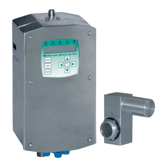
Pepperl+Fuchs 6000 Series Installation And Operation Manual
Purge/pressurization system
Hide thumbs
Also See for 6000 Series:
- Installation and operation manual (72 pages) ,
- Instruction manual (2 pages) ,
- Manual (72 pages)

Related Manuals for Pepperl+Fuchs 6000 Series


Summary of Contents for Pepperl+Fuchs 6000 Series
- Page 1 PROCESS AUTOMATION INSTALLATION AND OPERATION MANUAL 6000 SERIES PURGE/PRESSURIZATION SYSTEM...
- Page 2 With regard to the supply of products, the current issue of the following document is applicable: The General Terms of Delivery for Products and Services of the Electrical Industry, published by the Central Association of the Electrical Industry (Zentralverband Elektrotechnik und Elektroindustrie (ZVEI) e.V.) in its most recent version as well as the supplementary clause: "Expanded reservation of proprietorship".
-
Page 3: Table Of Contents
Sequence of events ......................... 23 Turning on power to the enclosure ....................23 Turning off power to the enclosure ....................24 Operation of the 6000 series and component kit ..............25 Operation ............................25 Set-up procedures of 6000 series system ..................29 Operation of the 6000 series system .....................29 Start up label located on 6000 series control unit ...............30... - Page 4 6000 Series Purge/Pressurization System I/O Manual Temperature sensor ........................48 Solenoid ............................49 General specifications ......................50 Certifications ........................... 52 Model number designators ..................... 53 Accessories ..........................54 Appendix ..........................55 Supplement: NFPA 496 information ..................56 Enclosure & device design ......................56 Establishing connection sizes, lengths &...
-
Page 5: Safety Note And Symbols Used
6000 Series Purge/Pressurization System I/O Manual Safety note and symbols used It is strongly urged that you follow all instructions and recommendations in this manual, in addition to all applicable codes, standards, and local requirements. Failure to do so voids all warranties, both implicit and explicit, and relieves the manufacturer of all liability. -
Page 6: General Instructions Regarding Atex
DIN ISO 8573-1 Class 1 to ensure a The user and/ or the installer is obligated to let only trouble free operation of the 6000 Series. competent, trained persons work at the 6000 Control Unit • are familiar with the regulations about safety and... - Page 7 6000 Series Purge/Pressurization System I/O Manual Class Particle Water Size Density Pressure Water Residual oil max in µm max in mg/m dew point in °C content in mg/m content in mg/m 0.01 6.000 7.800 9.400 Subject to modifications without notice...
-
Page 8: Certification Information
6000 Series Purge/Pressurization System I/O Manual Certification information Certification markings 6000 Series vent (1 vent or 1st vent when more than 1 vent in use) 6000 Series main unit 6000 Series vent (2nd vent when more than 1 vent in use) -
Page 9: Warning Labels
6000 Series Purge/Pressurization System I/O Manual Warning labels WARNING - Conduit seal must be installed within 18 inches of the enclosure. To prevent ignition of flammable or combustible atmospheres, disconnect power before servicing. WARNING - PRESSURIZED ENCLOSURE This enclosure must not be opened unless the area atmosphere is known to be below the ignitable concentration of combustible materials or unless all devices within have been de-energized. -
Page 10: Purpose
The hazardous area classification can be Class I, Division 1 / Zone 1. The 6000 series operates The 6000 series system can be set up for Class I & II/ Division 1 and Zone 1 & 21 applications in accordance by controlling and monitoring compressed instrument with the NEC-NFPA 70, NFPA496, UL913, CSA C22.2... -
Page 11: Main Unit
6000 Series Purge/Pressurization System I/O Manual Needle valve for pressurization of enclosure (requires flathead screwdriver for adjustment) Manifold for purging and pressurization Manifold with I.S. solenoid valve Connection to protective gas Type 4X (IP66) fittings for supply enclosure flow 316L stainless steel... -
Page 12: Electrical & Pneumatic Diagrams
6000 Series Purge/Pressurization System I/O Manual Electrical & pneumatic diagrams 12. When removing the pluggable terminal block, it is recommended that the electronics module be 6000 control unit power connections supported by pressing down on top of the EPCU General wiring notes to counter act the lifting force required to remove the connector. -
Page 13: Electrical Installation - Power And I.s. Wiring
6000 Series Purge/Pressurization System I/O Manual Electrical installation - power and I.S. wiring Prewired IS PWR 1+ IS PWR 1- Temp IS DATA 1A Module IS DATA 1B IS 1 SHLD Prewired IS PWR 2+ IS PWR 2- Power to... -
Page 14: Interface Board
6000 Series Purge/Pressurization System I/O Manual Temperature module connection (when Vent 2 is used) User interface connection (pre-wired) Vent 1 connection Vent 2 connection or Temperature Module connection Inputs 1 - 4, 5.0 V DC I.S. solenoid valve from manifold (pre-wired) I.S. - Page 15 6000 Series Purge/Pressurization System I/O Manual I.S. wiring No wiring is to be in the area between the terminals Non- I.S. wiring EPCU WARNING: To prevent ignition of the flammable Maintain a minimum space of 50.8 mm (2") between the I.S. wiring and the non - I.S. wiring.
-
Page 16: Pneumatic Requirements
0.35" (.889 mm). handle the flow and pressure requirements for purging The 6000 series control unit with the manifold can be and pressurization (see page 66, Establishing connection top, bottom, right, or left hand mounted on the enclosure. -
Page 17: Mounting Instructions
6000 Series Purge/Pressurization System I/O Manual Mounting Instructions Manifold assembly Left hand mount 6000 control unit housing 1/4 - 20 flathead screws (4 included) 3/8" stainless steel tube (included) EFC-6-SS (included) EFC-6-SS nut (included) Protective gas supply inlet 3/8" stainless steel tube (included) -
Page 18: Epv-6000 Vent
6000 Series Purge/Pressurization System I/O Manual EPV-6000 vent Tools: 1 1/2" NPT knockout ( 50.8 mm [2"] hole ) for Ø vent Vent mounted on the outside of the enclosure Locking nut w/grounding screw (included) Pressurized enclosure Seal gasket (included) Ø 2" (50.8 mm) -
Page 19: 6000 Control Unit With Housing "Wh
6000 Series Purge/Pressurization System I/O Manual 6000 Control unit with housing "WH" Tools: Appropriate sized drill bits or knockout holes 1 1/16" open end box wrench Bolts: 1/4-20 (provided), hole clearance = 6.86 mm (0.27") diameter EFC-6-SS (provided): hole clearance = 15.54 mm (0.61") diameter... - Page 20 6000 Series Purge/Pressurization System I/O Manual Tightening unit cover plate The screws on the unit cover plate must be tightened in the order shown on the diagram to Warning the right. The torque specification on this is 0.113 Nm (1 in-lb). Failure to do so can leave the unit improperly sealed.
-
Page 21: 6000 Series Component Kit
6000 Series Purge/Pressurization System I/O Manual 6000 Series Component kit Identification of components User interface Control unit and explosion proof / flameproof enclosure Optional pneumatic manifold with solenoid Component kit Atmospheric reference kit (6000-ACC-514482) for mounting vent inside the enclosure... -
Page 22: Electrical Diagrams
6000 Series Purge/Pressurization System I/O Manual Electrical diagrams 12. When removing the pluggable terminal block, it General wiring notes is recommended that the electronics module be supported by pressing down on top of the EPCU For power connections to the control unit and relay... -
Page 23: Electrical Installation - Power And I.s. Wiring
6000 Series Purge/Pressurization System I/O Manual Electrical installation - power and I.S. wiring Temp User IS Solenoid Module Interface Valve Vents Inputs 1-4 Prewired (BN) (BN) IS PWR 1 Vent 1 (BN) Power to IS PWR 2 EPCU Vent 2... -
Page 24: Component Kit Installation
6000 Series Purge/Pressurization System I/O Manual Component kit installation User interface Panel mount (internal mount, for hazardous area installation, NOT to be used in Dust, Class II/Zone 21 areas) Cable Mounting bracket Customer's nuts ( 4 provided) (provided) enclosure Tighten each to two... - Page 25 6000 Series Purge/Pressurization System I/O Manual External mount (non-hazardous locations only) Customer's enclosure Mounting screws (provided) Cable (provided) User interface (provided) Cut out for M12 connector 16,2 mm Ø (0.64") Environmental ratings are NOT maintained when Mounting in this manner is not approved for mounted in this manner.
- Page 26 6000 Series Purge/Pressurization System I/O Manual User Interface mounting template (panel mount) User interface mounting template (external mount) 83.0 mm 16.5 mm 53.5 mm 16.5 mm User (3.25'') (0.65'') (2.10'') (0.65'') interface (reference) ø 3.5 mm (0.15'') ø4.5 mm (0.15'')
-
Page 27: Sequence Of Events
6000 Series Purge/Pressurization System I/O Manual Sequence of events Turning on power to the enclosure Door open input off or not used No door open Immediate No immediate shutdown shutdown input off or not used Overload/temp input off or overload/temp... -
Page 28: Turning Off Power To The Enclosure
6000 Series Purge/Pressurization System I/O Manual Turning off power to the enclosure Control power relay input broken/shorted Control power relay Control power relay input Door open input broken/shorted Door open Door open input on Immediate shutdown input broken/shorted Immediate shutdown... -
Page 29: Operation Of The 6000 Series And Component Kit
• SMK-600-CK mounting hardware for 6000-UIC-01 relief vent is separate and is mounted to the enclosure. The 6000 series control unit is also available as a kit. The • One 5 m (16.5 ft.), quick disconnect cable for kit consists of the key components of the system, the 6000-UIC-01 control unit, and the user interface. - Page 30 Purge timing EPCU. This allows recalculation of the time based on When using the 6000 series in a gas or gas and dust this measurement. During the dynamic purge time, the location, the time for purging an enclosure can be based...
- Page 31 6000 Series Purge/Pressurization System I/O Manual engage the manifold solenoid valve manually when purging and manually disengage when a PRESSURE AS INPUT successful purging is complete. • SA – Semi-automatic mode requires the operator to engage the manifold solenoid valve manually when purging.
- Page 32 If using more than one (1) sensor, you may want the M12 (V1) connector and cable that come with the the control action to occur during the peak or vent. If using the 6000 series component kit, the vent is Note average temperature of the sensors.
-
Page 33: Set-Up Procedures Of 6000 Series System
Please refer to this manual and standards for explanation of requirements. Dust hazardous location 2. Apply power to the 6000 series system. • Enclosure must be cleaned out of all combustible dust. Purging can not be done to clean out 3. -
Page 34: Start Up Label Located On 6000 Series Control Unit
In this application, dust. Refer to "Conditions of Safe Use" Note Start up label located on 6000 series control unit MARKINGS for P/N: 514569 Model 6000 Type X / Ex px 250 CF / 7.2 CM Maximum Enclosure Volume... -
Page 35: The User Interface
SAFE PRESSURE LED (blue) ALARM FAULT LED (red) On: minimum over pressure Blinking: any alarm input detection Solid: 6000 series internal system fault SETUP: to enter setup mode Display: 2 x 20 LCD with backlight screen EXIT: to exit a menu... -
Page 36: Programming Menu
6000 Series Purge/Pressurization System I/O Manual Programming menu SETUP — PASSWORD — PURGE SETTINGS — — UNITS — — INPUT SETTINGS — — OUTPUT SETTINGS — — PASSWORD — — LANGUAGE — — BYPASS CONTROL — — RESTORE DEFAULTS —... -
Page 37: Purge Settings
6000 Series Purge/Pressurization System I/O Manual Purge settings PURGE — ENCLOSURE — USER DEFINED — SETTING CORRECT SETTINGS VOLUME — NUMB OF — 4 - 19 — SETTING CORRECT EXCHANGES. — PURGE FLOW — — SETTING CORRECT — — SETTING CORRECT —... -
Page 38: Inputs
6000 Series Purge/Pressurization System I/O Manual Inputs INPUT SETTINGS — INPUT 1 — INPUT 1 — DISABLED — SETTING CORRECT Y/N FUNCTION — INPUT 1 — IMMEDIATE SHTDN — SETTING CORRECT Y/N FUNCTION — DOOR OPEN ALARM — SETTING CORRECT Y/N —... - Page 39 6000 Series Purge/Pressurization System I/O Manual — INPUT 3 — INPUT 3 — DISABLED — SETTING CORRECT Y/N FUNCTION — INPUT 3 — IMMEDIATE SHTDN — SETTING CORRECT Y/N FUNCTION — DOOR OPEN ALARM — SETTING CORRECT Y/N — OVERLOAD —...
- Page 40 6000 Series Purge/Pressurization System I/O Manual — PRESS AS — PRESS FUNCTION — SETTING CORRECT INPUT — PRESS FUNCTION — DISABLED — SETTING CORRECT — CONTROL OUTPUT — SETTING CORRECT — CONTROL OUTPUT — SETTING CORRECT — CONTROL VALVE —...
- Page 41 6000 Series Purge/Pressurization System I/O Manual — TEMP INPUT 2 — TEMP FUNCTION — DISABLED — SETTING CORRECT Y/N — TEMP FUNCTION — IMMEDIATE SHTDN — SETTING CORRECT Y/N — DOOR OPEN ALARM — SETTING CORRECT Y/N — OVERLOAD —...
-
Page 42: Outputs
6000 Series Purge/Pressurization System I/O Manual Outputs OUTPUT SETTINGS — OUTPUT 1 FUNCTION — DISABLED — SETTING CORRECT Y/N — IMMED SHUTDN ALARM — SETTING CORRECT Y/N — DOOR OPEN ALARM — SETTING CORRECT Y/N — OVERLOAD/TEMP — SETTING CORRECT Y/N ALARM —... -
Page 43: Password
6000 Series Purge/Pressurization System I/O Manual Password PASSWORDS — CHANGE SETUP — CREATE SETUP — VERIFY SETUP PASSWORD PASSWORD — CHANGE BYPASS — ENTER BYPASS — CREATE BYPASS — VERIFY BYPASS PASSWORD PASSWORD PASSWORD Language LANGUAGE — ENGLISH — SETTING CORRECT Y/N —... -
Page 44: Stats
6000 Series Purge/Pressurization System I/O Manual Stats STATS — STATISTICS — — ALARM — — FAULT — — CLEAR — STATISTICS — CLEAR FAULT — Subject to modifications without notice Copyright Pepperl+Fuchs Pepperl+Fuchs Group USA: +1 330 486 0002 Germany: +49 621 776 2222 Singapore: +65 6779 9091 www.pepperl-fuchs.com... -
Page 45: Statistics
6000 Series Purge/Pressurization System I/O Manual Statistics This provides system operating information. These fields are read only. STATISTICS — TEMPERATURES — HUB SENSOR STATS — CURRENT HUB — CURRENT HUB TEMP TEMP XXX °F — MAX HUB TEMP — MAX HUB TEMP XXX °F... - Page 46 6000 Series Purge/Pressurization System I/O Manual — MAX PURGE — MAX PURGE PRESSURE PRESSURE X.XX IN WC — LAST PURGE TIME — LAST PURGE TIME XXXX MIN — MIN PURGE FLOW — MIN PURGE FLOW XX CFM — MAX PURGE FLOW —...
-
Page 47: Alarm Fault
6000 Series Purge/Pressurization System I/O Manual Alarm Fault This provides the reason for the last system alarm. This provides the reason for the system fault. ALARM — NONE FAULT — NONE — NO SAFE PRESSURE — CONTROL OUTPUT 1 —... -
Page 48: Clear Statistics
6000 Series Purge/Pressurization System I/O Manual Clear statistics CLEAR STATISTICS — CLEAR STATS Y 0R N — SETTING CORRECT Clear fault CLEAR FAULT — CLEAR FAULT Y 0R N — SETTING CORRECT Operation screen This provides the system information. OPERATION —... -
Page 49: System Dimensions
6000 Series Purge/Pressurization System I/O Manual System dimensions 6000 series control unit 183.0 mm 32.0 mm (7.20'') (1.25'') 32.0 mm (1.25'') 220.5 mm (8.70'') 183.0 mm (7.20'') Clearance hole for 9/16 - 18 hardware 3 holes Mtg hole for 1/4 - 20 hardware 3 holes 5.0 mm... -
Page 50: 6000 Series Component Kit
6000 Series Purge/Pressurization System I/O Manual 6000 series component kit EPCU with Ex enclosure 3/4" NPT thread #5/16-18 mounting 120.5 mm hardware (4.75'') 3/4''NPT thread 1.3 mm 25.5 mm (1.00'') 51.0 mm 60.5 mm (2.00'') (2.40'') #5/16-18 mounting hardware User interface with mounting bracket (panel mount) 30.0 mm... -
Page 51: Temperature Hub
6000 Series Purge/Pressurization System I/O Manual User-interface without mounting bracket (external mount) 20.5 mm 83.0 mm 124.0 mm 30 mm (4.90'') (0.80'') (3.25'') (1.20'') Grounding lug (included) #8-32 thread mounting location x 2 62.0 mm 27.0 mm (2.45'') (1.05'') The user-interface can be mounted either... -
Page 52: Temperature Sensor
6000 Series Purge/Pressurization System I/O Manual Temperature sensor 2.0 mm 13.0 mm 10.0 mm 2.0 mm (0.08") (0.50") (0.40") (0.08") 20.0 mm 5.0 mm ø 3.0 mm (0.20") (0.80") (0.10") Subject to modifications without notice Copyright Pepperl+Fuchs Pepperl+Fuchs Group USA: +1 330 486 0002... -
Page 53: Solenoid
6000 Series Purge/Pressurization System I/O Manual Solenoid 22.0 mm 38.0 mm (0.85") (1.50") #1/4 - 20 UNC THD 9.5 mm (0.85") Deep Needle Valve screwdriver slot drive 30.0 mm (1.20") 10.5 mm (0.40") #1/4 - 20 UNC THD 8.0 mm (3.15") deep c'sink 82˚... -
Page 54: General Specifications
General specifications Alarm fault: RED blinking - any alarm input detected Enclosure volume: 7.2 m (250 ft RED solid – 6000 series system fault Number of volume exchange: 4 to 19 I.S. solenoid valve output Refer to drawing 116-013UL-112. Hazardous environment:... -
Page 55: Mechanical Specifications
6000 Series Purge/Pressurization System I/O Manual Outlet fitting from manifold: 3/8" bulkhead fitting Parts List (included) Control unit with housing Mechanical specifications (1) 6000 control unit (1) bracket for mounting control unit 6000 control unit (1) EFC-6-SS Protection class (all electronics):... -
Page 56: Certifications
6000 Series Purge/Pressurization System I/O Manual Certifications Complete Unit Component Kit Class I, Division 1, Groups A, B, C, D T4 Class I, Division 1, Groups A, B, C, D T4 Class I, Zone 1, Groups IICT4 Class I, Zone 1, Groups IICT4... -
Page 57: Model Number Designators
6000 Series Purge/Pressurization System I/O Manual Model number designators Control unit 6000 - DV - S2 - UN - WH - AC AC - 100 - 250 V AC DC - 20 - 30 V DC WH - with stainless steel housing... -
Page 58: Accessories
6000-ACC-514480 Mounting bolts for bracket to enclosure and control unit to bracket. 4 pcs. 6000-ACC-514481 3/8" filter and regulator with fitting for connection to 6000 series manifold 6000-ACC-514482 Atmospheric reference kit for mounting EPV-6000-AA vent inside enclosure 1 - 1/2" locknut with ground and gasket for EPV-6000 vent mounted outside enclosure... -
Page 59: Appendix
6000 Series Purge/Pressurization System I/O Manual Appendix Subject to modifications without notice Copyright Pepperl+Fuchs Pepperl+Fuchs Group USA: +1 330 486 0002 Germany: +49 621 776 2222 Singapore: +65 6779 9091 www.pepperl-fuchs.com pa-info@us.pepperl-fuchs.com pa-info@de.pepperl-fuchs.com pa-info@sg.pepperl-fuchs.com... -
Page 60: Supplement: Nfpa 496 Information
6000 Series Purge/Pressurization System I/O Manual Supplement: NFPA 496 information Total Volume Calculation Enclosure & device design 1. The total volume of all pressurized enclosures, Enclosure design requirements devices and wireways must be considered. 1. All windows must be shatterproof and sized as 2. - Page 61 6000 Series Purge/Pressurization System I/O Manual nameplate). Devices may only be accessed after power has been removed and the device has been allowed to cool to a safe temperature, or the area is positively known to be nonhazardous. Subject to modifications without notice...
-
Page 62: Establishing Connection Sizes, Lengths & Bends
6000 Series Purge/Pressurization System I/O Manual Establishing connection sizes, lengths & bends Typical single protected enclosure connections with vent Enclosure protection vent (required) 1/2" protective gas supply header Protected Enclosure enclosure protection Supply system System Enclosure Multi - enclosure Optional remote... -
Page 63: Programming Worksheet
Part No. 514443 Drawing No. 129-0268A (TDOCT-1372BENG) 07/2010... - Page 64 Part No. 514443 Drawing No. 129-0268A (TDOCT-1372BENG) 07/2010...
- Page 65 Part No. 514443 Drawing No. 129-0268A (TDOCT-1372BENG) 07/2010...
- Page 66 Part No. 514443 Drawing No. 129-0268A (TDOCT-1372BENG) 07/2010...
- Page 67 Part No. 514443 Drawing No. 129-0268A (TDOCT-1372BENG) 07/2010...
- Page 68 Part No. 514443 Drawing No. 129-0268A (TDOCT-1372BENG) 07/2010...
- Page 69 Part No. 514443 Drawing No. 129-0268A (TDOCT-1372BENG) 07/2010...
-
Page 70: Notes
6000 Series Purge/Pressurization System I/O Manual Notes: Subject to modifications without notice Copyright Pepperl+Fuchs Pepperl+Fuchs Group USA: +1 330 486 0002 Germany: +49 621 776 2222 Singapore: +65 6779 9091 www.pepperl-fuchs.com pa-info@us.pepperl-fuchs.com pa-info@de.pepperl-fuchs.com pa-info@sg.pepperl-fuchs.com... - Page 71 6000 Series Purge/Pressurization System I/O Manual Subject to modifications without notice Copyright Pepperl+Fuchs Pepperl+Fuchs Group USA: +1 330 486 0002 Germany: +49 621 776 2222 Singapore: +65 6779 9091 www.pepperl-fuchs.com pa-info@us.pepperl-fuchs.com pa-info@de.pepperl-fuchs.com pa-info@sg.pepperl-fuchs.com...
- Page 72 Twinsburg · Ohio · USA Tel. +55 11 4341 8448 Tel. +1 330 486 0002 E-Mail: pa-info@br.pepperl-fuchs.com E-Mail: pa-info@us.pepperl-fuchs.com www.pepperl-fuchs.com Subject to modifications • © 2010 PEPPERL+FUCHS, INC. • Printed in USA • Part No. 514443 Drawing No. 129-0268A (TDOCT-1372BENG) 07/2010...
Need help?
Do you have a question about the 6000 Series and is the answer not in the manual?
Questions and answers