Table of Contents
Advertisement
Quick Links
Advertisement
Table of Contents

Related Manuals for Unverferth Orthman Stalk Pullr 600


Summary of Contents for Unverferth Orthman Stalk Pullr 600
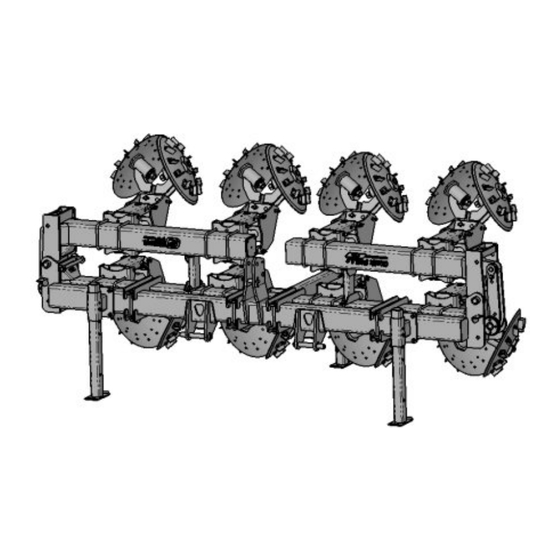
- Page 1 Residue Managment 600 Stalk Pullr Part No. L125-031...
- Page 2 600 STALK PULLER — Introduction Foreword This symbol identifies important safety messages. When you see it, read the message that follows and be alert to the possibility of personal injury. Remember, safety instructions stated in this manual are for your protection. Read them carefully and follow them closely when working around or using this machine.
-
Page 3: Product Information
Please fill out and retain this portion for your records. All products manufactured by Unverferth Mfg. Co., Inc. are warranted to be free from material and workmanship defects for one full year from time of consumer delivery. Your local dealer will gladly assist you with any warranty questions. -
Page 4: Table Of Contents
600 STALK PULLER — Introduction Table of Contents SECTION I Safety General Hazard Information ....................... 1-2 Safety Decals ..........................1-3 Following Safety Instructions ..................... 1-4 Before Servicing or Operating ....................1-4 During Operation ........................1-5 Before Transporting ........................1-5 During Transport ......................... 1-5 Preparing for Emergencies...................... - Page 5 600 STALK PULLER — Introduction Table of Contents SECTION III Operations General Operation Information ....................3-2 Preparing Tractor ........................3-2 Preparing Stalk Puller ........................ 3-2 Bolts & Nuts........................3-2 Pins ............................3-2 Lubrication ........................... 3-2 Wing Fold Degree Adjustment ....................3-3 Adjustable Wing Rest .........................
- Page 6 600 STALK PULLER — Introduction Table of Contents SECTION V Parts Decals ............................5-2 Hitch Components ........................5-3 Hitch Clamp Components ......................5-4 Bar Stand Components ......................5-5 180 Degree Wing Rest Components ..................5-6 170 Degree Wing Rest Components ..................5-7 Adjustable Wing Rest Components ....................
- Page 7 — Safety 600 STALK PULLER SECTION I Safety General Hazard Information ....................... 1-2 Safety Decals ..........................1-3 Following Safety Instructions ..................... 1-4 Before Servicing or Operating ....................1-4 During Operation ........................1-5 Before Transporting ........................1-5 During Transport ......................... 1-5 Preparing for Emergencies......................
-
Page 8: Safety
It is said that, “the best kind of a safety device is a careful operator.” We, at Unverferth Mfg. Co., Inc. ask that you be that kind of operator. -
Page 9: Safety Decals
— Safety 600 STALK PULLER Safety Decals • REPLACE LOST, DAMAGED, PAINTED, OR UNREADABLE DECALS IMMEDIATELY. IF PARTS THAT HAVE DECALS ARE REPLACED, ALSO MAKE SURE TO INSTALL NEW DECALS. THESE DECALS INFORM AND REMIND THE OPERATOR WITH OPERATIONAL INFORMATION AND SAFETY MESSAGES. PART NO. -
Page 10: Following Safety Instructions
— Safety 600 STALK PULLER Following Safety Instructions • Read and understand this operator’s manual before operating. • All machinery should be operated only by trained and authorized personnel. • To prevent machine damage, use only attachments and service parts approved by the manufacturer. •... -
Page 11: During Operation
— Safety 600 STALK PULLER During Operation • Regulate speed to working conditions. Maintain complete control at all times. • Never service or lubricate equipment when in operation. • Use extreme care when operating close to ditches, fences, or on hillsides. •... -
Page 12: Preparing For Emergencies
— Safety 600 STALK PULLER Preparing for Emergencies • Keep a first aid kit and properly rated fire extinguisher nearby. • Keep emergency numbers for fire, rescue, and poison control personnel near the phone. Wearing Protective Equipment • Wear clothing and personal protective equipment appropriate for the job. •... -
Page 13: Set Up
— Set Up 600 STALK PULLER SECTION II Set Up General Set Up Information ....................... 2-2 Basic Set Up ..........................2-3 Hydraulic System ......................... 2-3 SMV Emblem ........................2-3 Light and Light Bracket Set Up ....................2-4 Outer Lights ......................... 2-4 Inner Lights ......................... -
Page 14: General Set Up Information
— Set Up 600 STALK PULLER General Set Up Information This section contains all of the instructions required for the complete assembly of the scraper. For your safety, and the safety of others, use proper tools and equipment and always use safe working procedures. -
Page 15: Basic Set Up
— Set Up 600 STALK PULLER Basic Set Up Due to shipping requirements and various dealer-installed options, some initial implement set up will be required after it arrives from the factory. Use the following procedures as needed for initial implement set up. Hydraulic System Check all hoses and cylinders for signs of leakage. -
Page 16: Light And Light Bracket Set Up
— Set Up 600 STALK PULLER Light and Light Bracket Set Up For Outer Lights: NOTE: The left and right light brackets should be adjusted according to the degree at which the wings fold. 1. Remove the hex nut and capscrew from the top of the light bracket mount. -
Page 17: Inner Lights
— Set Up 600 STALK PULLER Light and Light Bracket Set Up For Inner Lights: Inner light brackets must each be mounted equaly from the center of the tool bar and be a total distance of between 4’ and 10’ from each other. The inner red lights will only have a lense on one side of the light and it should be visible from the rear of the toolbar. -
Page 18: Overhead Layouts
— Set Up 600 STALK PULLER Overhead Layouts 4 Row 36” Spacing Configuration 24” 36” 78” 156” 4 Row 38” Spacing Configuration 21” 38” 78” 156”... -
Page 19: Row 40" Spacing Configuration
— Set Up 600 STALK PULLER Overhead Layouts 4 Row 40” Spacing Configuration 18” 40” 78” 156” 6 Row 30” Spacing Configuration 15” 30” 90” 180”... -
Page 20: Row 36" Spacing Configuration
— Set Up 600 STALK PULLER Overhead Layouts 6 Row 36” Spacing Configuration 18” 36” 108” 216” 6 Row 38” Spacing Configuration 13” 38” 108” 216”... -
Page 21: Row 40" Spacing Configuration
— Set Up 600 STALK PULLER Overhead Layouts 6 Row 40” Spacing Configuration 8” 40” 108” 216” 8 Row 30” Spacing Configuration 15” 30” 120” 240”... -
Page 22: Row 36" Spacing Configuration
— Set Up 600 STALK PULLER Overhead Layouts 8 Row 36” Spacing Configuration 18” 36” 144” 288” 8 Row 38” Spacing Configuration 11” 38” 144” 288” 2-10... -
Page 23: Row 40" Spacing Configuration
— Set Up 600 STALK PULLER Overhead Layouts 8 Row 40” Spacing Configuration 10” 40” 150” 300” 12 Row 30” Spacing Configuration 10” 30” 175” 350” 2-11... -
Page 24: Row 36" Spacing Configuration
— Set Up 600 STALK PULLER Overhead Layouts 12 Row 36” Spacing Configuration 18” 36” 216” 432” 12 Row 38” Spacing Configuration 7” 38” 216” 432” 2-12... -
Page 25: Row 40" Spacing Configuration
— Set Up 600 STALK PULLER Overhead Layouts 12 Row 40” Spacing Configuration 14” 40” 234” 468” 16 Row 30” Spacing Configuration 15” 30” 240” 480” 2-13... -
Page 26: Row 38" Spacing Configuration
— Set Up 600 STALK PULLER Overhead Layouts 16 Row 38” Spacing Configuration 22” From Outside of Toolbar to Middle of First Row Unit 38” 307” 614” 16 Row 40” Spacing Configuration 7” From Outside of Toolbar to Middle of First Row Unit 40”... -
Page 27: Row 36" Spacing Configuration
— Set Up 600 STALK PULLER Overhead Layouts 18 Row 36” Spacing Configuration 16” From Outside of Toolbar to Middle of First Row Unit 36” 322” 644” 2-15... - Page 28 — Operation 600 STALK PULLER SECTION III Operation General Operation Information ....................3-2 Preparing Tractor ........................3-2 Preparing Stalk Puller ........................ 3-2 Bolts & Nuts........................3-2 Pins ............................3-2 Lubrication ........................... 3-2 Wing Fold Degree Adjustment ....................3-3 Adjustable Wing Rest ......................... 3-4 90 Degree Fold Procedure ......................
-
Page 29: General Operation Information
— Operation 600 STALK PULLER General Operation Information • READ AND UNDERSTAND SAFETY RULES BEFORE OPERATING OR SERVICING THIS MACHINE. REVIEW "SAFETY" SECTION IN THIS MANUAL IF NECESSARY. • CRUSHING CAN CAUSE SERIOUS INJURY OR DEATH. DO NOT STAND BETWEEN TOW- ING VEHICLE AND IMPLEMENT WHEN HITCHING. -
Page 30: Wing Fold Degree Adjustment
— Operation 600 STALK PULLER Wing Folding Degree Adjustment MOVING WINGS CAN CAUSE SERIOUS INJURY OR DEATH. KEEP AWAY FROM FOLDING • AND UNFOLDING WINGS. NOTE: Most Vertical Fold Toolbars can be folded to either 90˚, 115˚, 135°, or 180˚. Modifications may need to be made to the current fold angle due to transportation, storage, and application issues of the particular operation NOTE: 12 Row 36”, 38”, 40”... -
Page 31: Adjustable Wing Rest
— Operation 600 STALK PULLER Adjustable Wing Rest MOVING WINGS CAN CAUSE SERIOUS INJURY OR DEATH. KEEP AWAY FROM FOLDING • AND UNFOLDING WINGS. NOTE: Vertical Fold Tillage Toolbars are standard with 180° fold configuration. If 115° or 135° fold configuration is desired, adjustable wing rests must be ordered separately (see adjustable wing rest parts page). - Page 32 — Operation 600 STALK PULLER Adjustable Wing Rest MOVING WINGS CAN CAUSE SERIOUS INJURY OR DEATH. KEEP AWAY FROM FOLDING • AND UNFOLDING WINGS. Adjusting The Wing Rest 1. Leave the unit attached to the tractor, raise the unit, then lower the support stands to the ground. 2.
-
Page 33: Degree Fold Procedure
— Operation 600 STALK PULLER 90 Degree Folding Procedure MOVING WINGS CAN CAUSE SERIOUS INJURY OR DEATH. KEEP AWAY FROM FOLDING • AND UNFOLDING WINGS. NOTE: The 90 degree fold transport lock (sold seperately) is mandatory for the 90 degree fold position. -
Page 34: Field Operation
— Operation 600 STALK PULLER Stalk Pullr Field Operation Rigid Operation MOVING WINGS CAN CAUSE SERIOUS INJURY OR DEATH. KEEP AWAY FROM FOLDING • AND UNFOLDING WINGS. 1. With the wings completly unfolded, move the wing lock pin from the storage position and install it into the wing lock position. -
Page 35: Field Adjustments
— Operation 600 STALK PULLER Stalk Pullr Field Adjustments • FALLING OBJECTS CAN CAUSE SERIOUS INJURY OR DEATH. DO NOT WORK UNDER THE MACHINE AT ANY TIME WHILE BEING HOISTED. BE SURE ALL LIFTING DEVICES AND SUPPORTS ARE RATED FOR THE LOADS BEING HOISTED. THESE ASSEMBLY INSTRUCTIONS WILL REQUIRE SAFE LIFTING DEVICES UP TO 500 LBS. - Page 36 — Operation 600 STALK PULLER Stalk Pullr Field Adjustments (continued) V-Disc Pinch Point Pressure NOTE: Pressure applied to the pinch point of the V-discs increases the ‘slicing’ effect of the two disks, however, too much pressure will decrease the rolling performance of the V-Disk. NOTE: The amount of pressure to be applied to the pinch point should only be enough to spin both disks when one disk is spun.
- Page 37 — Operation 600 STALK PULLER Stalk Pullr Field Adjustments (continued) V-Disc Orientation NOTE: Standard orientation of the V-Disks is left overlaps right. Over the life of the V-Disks a groove will appear in the LH V-Disk and the RH V-Disk will become dull. When this happens, the V-Disk orientation must be changed.
-
Page 38: Chopper Height
— Operation 600 STALK PULLER Stalk Pullr Field Adjustments (continued) Chopper Height Adjustment NOTE: For implements equipped with the optional chopper units, the chopper unit height may be adjusted to fine-tune desirable performance. FIG. 3-17 1. Use a safe lifting device to hold the chopper assembly up while adjusting. -
Page 39: Hitching To Tractor
— Operation 600 STALK PULLER Hitching to Tractor 3 Point Hitch Tractor Connection 1. Back up tractor to the implement hitch. Place the tractor in park, turn off the engine, and remove the key before connecting the implement. Injury or deathcan result from being trapped between the tractor and implement. -
Page 40: Transport And Field Positions
— Operation 600 STALK PULLER Transport and Field Positions Transport Position: Regulate speed to road conditions and maintain complete control. Be aware of obstructions above, below, and around the implement when in operation or transport. Connect the implement to the tractor hitch. Raise the tractor hitch to it’s highest point. -
Page 41: Maintenance
— Maintenance 600 STALK PULLER SECTION IV Maintenance Lubrication ..........................4-2 Mount and Parellel Linkage Disassembly and Assembly ............4-4 V-Disc Disassembly and Assembly .................... 4-6 V-Disc Mount Leg Disassembly and Assembly ................. 4-7 Chopper Unit Disassembly and Assembly ................. 4-8 Gauge Wheel Disassembly and Assembly ................. -
Page 42: Lubrication
— Maintenance 600 STALK PULLER Lubrication Grease all zerks on the 5|TT TRACK TILLr® using a high-quality, multi-purpose grease. Follow the recommended hourly service intervals illustrated below. Lubrication Service Intervals # of Grease Points Interval (Hours) Gauge Wheel Pivot Adjustment Crank Wheel Hub Bearing Wing Pivot 6 (Single Folding Toolbar) - Page 43 — Maintenance 600 STALK PULLER Lubrication Wing Fold Linkage Chopper Unit Bearings FIG. 4-5 FIG. 4-6...
-
Page 44: Mount And Parellel Linkage Disassembly And Assembly
— Maintenance 600 STALK PULLER Mount and Parrellel Linkage Disassembly and Assembly • TIPPING OR MOVEMENT OF THE MACHINE CAN CAUSE SERIOUS INJURY OR DEATH. BE SURE MACHINE IS SECURELY BLOCKED. • FALLING OBJECTS CAN CAUSE SERIOUS INJURY OR DEATH. DO NOT WORK UNDER THE MACHINE AT ANY TIME WHILE BEING HOISTED. -
Page 45: Mount And Parellel Linkage Disassembly And Assembly
— Maintenance 600 STALK PULLER Mount and Parrellel Linkage Disassembly and Assembly (Continued) 7. Remove the rear capscrews, flange nuts, and bushings from the parellel linkages, then remove the parellel linkages from the row unit. (Fig. 4-9) 8. Inspect parts for wear or damage and replace if neccesary. 9. -
Page 46: V-Disc Disassembly And Assembly
— Maintenance 600 STALK PULLER V-Disc Disassembly and Assembly 1. Leave the unit attached to the tractor, raise the unit, then lower the support stands to the ground. 2. Lower the unit until it is supported by the stands, then set the tractors parking brake and remove the key. -
Page 47: V-Disc Mount Leg Disassembly And Assembly
— Maintenance 600 STALK PULLER V-Disc Mount Leg Disassembly and Assembly 1. Leave the unit attached to the tractor, raise the unit, then lower the support stands to the ground. 2. Lower the unit until it is supported by the stands, then set the tractors parking brake and remove the key. -
Page 48: Chopper Unit Disassembly And Assembly
— Maintenance 600 STALK PULLER Chopper Unit Disassembly and Assembly 1. Leave the unit attached to the tractor, raise the unit, then lower the support stands to the ground. 2. Lower the unit until it is supported by the stands, then set the tractors parking brake and remove the key. -
Page 49: Gauge Wheel Disassembly And Assembly
— Maintenance 600 STALK PULLER Gauge Wheel Disassembly and Assembly 1. Leave the unit attached to the tractor, raise the unit, then lower the support stands to the ground. 2. Lower the unit until it is supported by the stands, then set the tractors parking brake and remove the key. -
Page 50: Toolbar Internal Cylinder Removal
— Maintenance 600 STALK PULLER Toolbar Internal Cylinder Removal • KEEP HANDS CLEAR OF PINCH POINT AREAS. • EYE PROTECTION AND OTHER APPROPRIATE PERSONAL PROTECTIVE EQUIPMENT MUST BE WORN WHILE SERVICING IMPLEMENT. • HIGH-PRESSURE FLUIDS CAN PENETRATE THE SKIN AND CAUSE SERIOUS INJURY OR DEATH. - Page 51 — Maintenance 600 STALK PULLER Toolbar Internal Cylinder Removal (Continued) 9. Remove the locking capscrew, lock washer FIG. 4-22 and flat washer that hold the cylinder pin in place, then remove the cylinder pin from the assembly. (Fig. 4-22) Cylinder Pin 10.
-
Page 52: Storage
— Maintenance 600 STALK PULLER Storage Your implement is an important investment. Spend a little time to protect it from destructive rust and corrosion. You will be repaid in longer service life and better performance. Do the following before placing the implement in storage: 1. -
Page 53: Complete Torque Chart
— Maintenance 600 STALK PULLER Complete Torque Chart Capscrews - Grade 5 NOTE: • Grade 5 capscrews can be identified by three radial dashes on the head. • For wheel torque requirements, refer to Wheels and Tires. • Tighten U-bolts evenly and equally to have the same number of threads exposed on each end. FOOT NEWTON SIZE... -
Page 54: Capscrews - Grade 8
— Maintenance 600 STALK PULLER Complete Torque Chart (continued) Capscrews - Grade 8 NOTE: • Grade 8 capscrews can be identified by six radial dashes on the head. • For wheel torque requirements, refer to Wheels and Tires. • Tighten U-bolts evenly and equally to have the same number of threads exposed on each end. FOOT NEWTON SIZE... -
Page 55: Hydraulic Fittings
— Maintenance 600 STALK PULLER Hydraulic Fittings – Torque and Installation Tightening O-Ring Fittings 1. Inspec t c omp on e nt s f or d ama ge o r O-Ring fittings contamination. Do not connect any other type of fitting to an O-ring fitting. 2. - Page 56 — Maintenance 600 STALK PULLER Hydraulic Fittings – Torque and Installation Tightening JIC Fittings 1. Inspect all components for damage or contamination. Do not connect any other JIC fittings type of fitting to a JIC fitting. 2. Lubricate the threads. 3.
- Page 57 — Maintenance 600 STALK PULLER Notes 4-17...
- Page 58 — Parts 600 STALK PULLER SECTION V Parts Decals ............................5-2 Hitch Components ........................5-3 Hitch Clamp Components ......................5-4 Bar Stand Components ......................5-5 180 Degree Wing Rest Components ..................5-6 170 Degree Wing Rest Components ..................5-7 Adjustable Wing Rest Components .................... 5-8 Toolbar Hinge Components ......................
-
Page 59: Decals
— Parts 600 STALK PULLER Decals Please visit www.unverferth.com/parts/ for the most current parts listing. ITEM PART NO. DESCRIPTION NOTES L153-1012 Decal, Orthman by Unverferth L153-1008 Decal, 600 Stalk Pullr L153-172 Decal, Reflective Yellow L153-171 Decal, Reflective Orange L153-173 Decal, Reflective Red... -
Page 60: Hitch Components
— Parts 600 STALK PULLER Hitch Components Please visit www.unverferth.com/parts/ for the most current parts listing. Cat. 4 Hitches Are Only Available On Models with Double Folding Toolbars ITEM PART NO. DESCRIPTION NOTES L601-140 Low Lift Hitch Package, 90” Category 3/3N L601-151 Low Lift Hitch Package, 110”... - Page 61 — Parts 600 STALK PULLER Hitch Clamp Components Please visit www.unverferth.com/parts/ for the most current parts listing. ITEM PART NO. DESCRIPTION NOTES L601-360 Clamp Assembly, Heavy Duty - Medium 4” Spacing L302-571 Clamp L100-199 Capcsrew, 1”-8UNC x 10” Grade 8...
- Page 62 — Parts 600 STALK PULLER Bar Stand Components Please visit www.unverferth.com/parts/ for the most current parts listing. ITEM PART NO. DESCRIPTION NOTES L600-354 48” Bar Stand Kit L600-356 36” L303-744 Stand Tube, 48” L303-840 Stand Tube, 36” L301-030 Stand Mount L315-027 U-Bolt, 5/8”-11UNC x 5”...
- Page 63 — Parts 600 STALK PULLER 180 Degree Wing Rest Components Please visit www.unverferth.com/parts/ for the most current parts listing. ITEM PART NO. DESCRIPTION NOTES L301-545 180 Degree Wing Rest L315-031 U-Bolt, 3/4”-10UNC x 7” x 7” L108-022 Lock Washer, 3/4”...
- Page 64 — Parts 600 STALK PULLER 170 Degree Wing Fold Assembly Components Please visit www.unverferth.com/parts/ for the most current parts listing. ITEM PART NO. DESCRIPTION NOTES L301-524 170 Degree Wing Rest L146-008 Rubber Bumper L315-031 U-Bolt, 3/4”-10UNC x 7” x 7”...
-
Page 65: Adjustable Wing Rest Components
— Parts 600 STALK PULLER Adjustable Wing Rest Components Please visit www.unverferth.com/parts/ for the most current parts listing. - Page 66 — Parts 600 STALK PULLER Adjustable Wing Rest Components Please visit www.unverferth.com/parts/ for the most current parts listing. ITEM PART NO. DESCRIPTION NOTES L600-074 Adjustbale Wing Rest Kit L600-101 Adjustable Wing Rest Kit (Short) L300-065 Mount Bracket L300-071 Reciever Tube...
-
Page 67: Toolbar Hinge Components
— Parts 600 STALK PULLER Toolbar Hinge Components Please visit www.unverferth.com/parts/ for the most current parts listing. ITEM PART NO. DESCRIPTION NOTES L301-146 Toolbar Pivot Pin L301-157 Toolbar Locking Pin L134-005 Toolbar Pivot Bushing L134-040 Toolbar Cylindser Bushing L110-001 Grease Fitting... -
Page 68: Single Folding Toolbar Light Mount And Smv Sign Components
— Parts 600 STALK PULLER Single Folding Toolbar Light Mounts and SMV Sign Components Please visit www.unverferth.com/parts/ for the most current parts listing. ITEM PART NO. DESCRIPTION NOTES L301-567 Adjustable Light Bracket, Right L301-568 Adjustable Light Bracket, Left L301-563 Adjustable Light Bracket Arm... -
Page 69: Double Folding Toolbar Light Mount And Smv Sign Components
— Parts 600 STALK PULLER Double Folding Toolbar Light Mounts and SMV Sign Components Please visit www.unverferth.com/parts/ for the most current parts listing. ITEM PART NO. DESCRIPTION NOTES L341-822 Outer Light Mount (Left) L341-821 Outer Light Mount (Right) L341-825 Inner Light Mount (Left) -
Page 70: Rigid Toolbar Light Mount And Smv Sign Components
— Parts 600 STALK PULLER Rigid Toolbar Light Mounts and SMV Sign Components Please visit www.unverferth.com/parts/ for the most current parts listing. ITEM PART NO. DESCRIPTION NOTES L301-573 Light Mount L153-109 SMV Sign L385-183 SMV Sign Mount L333-499 SMV Sign Mounting Strap L315-026 U-Bolt, 3/8”-16UNC x 7’... -
Page 71: 180 Degree Wing Fold Assembly Components
— Parts 600 STALK PULLER 180 Degree Wing Fold Assembly Components Please visit www.unverferth.com/parts/ for the most current parts listing. 5-14... - Page 72 — Parts 600 STALK PULLER 180 Degree Wing Fold Assembly Components Please visit www.unverferth.com/parts/ for the most current parts listing. ITEM PART NO. DESCRIPTION NOTES L194-499 Cylinder, 4” x 24” L301-980 Connecting Strap L301-548 Linkage Pin L301-982 Guide Wheel L301-512...
-
Page 73: 170 Degree Wing Fold Assembly Components
— Parts 600 STALK PULLER 170 Degree Wing Fold Assembly Components Please visit www.unverferth.com/parts/ for the most current parts listing. 5-16... - Page 74 — Parts 600 STALK PULLER 170 Degree Wing Fold Assembly Components Please visit www.unverferth.com/parts/ for the most current parts listing. ITEM PART NO. DESCRIPTION NOTES L194-499 Hydraulic Cylinder, 4” x 24” L301-502 Connecting Strap L301-548 Linkage Pin L301-802 Guide Wheel...
-
Page 75: Row Unit Mounting And Linkage Components
— Parts 600 STALK PULLER Row Unit Mounting and Linkage Components Please visit www.unverferth.com/parts/ for the most current parts listing. 5-18... - Page 76 — Parts 600 STALK PULLER Row Unit Mounting and Linkage Components Please visit www.unverferth.com/parts/ for the most current parts listing. ITEM PART NO. DESCRIPTION NOTES L386-166 Row Unit Body L386-260 Parellel Linkage L386-189 Row Unit Mount Plate L386-193 Down Pressure Spring Trunnion...
-
Page 77: V-Disc And Mount Leg Components
— Parts 600 STALK PULLER V-Disc and Mount Leg Components Please visit www.unverferth.com/parts/ for the most current parts listing. ITEM PART NO. DESCRIPTION NOTES L386-195 V-Disc Mount Leg Includes Items 3 and 4 L386-141 Disc, 24” (With Cleats) Includes Items 2, 5, 9, and 11 L386-122 Disc, 24”... - Page 78 — Parts 600 STALK PULLER Notes Please visit www.unverferth.com/parts/ for the most current parts listing. 5-21...
-
Page 79: Chopper Unit Components
— Parts 600 STALK PULLER Chopper Unit Components Please visit www.unverferth.com/parts/ for the most current parts listing. 5-22... - Page 80 — Parts 600 STALK PULLER Chopper Unit Components Please visit www.unverferth.com/parts/ for the most current parts listing. ITEM PART NO. DESCRIPTION NOTES L386-154 Chopper Unit Mounting Yoke L386-157 Chopper Unit Mounting Plate L386-150 Chopper Unit Reel L152-628 Chopper Unit Blade...
-
Page 81: Gauge Wheel Components
— Parts 600 STALK PULLER Gauge Wheel Components Please visit www.unverferth.com/parts/ for the most current parts listing. 5-24... - Page 82 — Parts 600 STALK PULLER Gauge Wheel Components Please visit www.unverferth.com/parts/ for the most current parts listing. ITEM PART NO. DESCRIPTION NOTES 111522W Gauge Wheel Tire Assembly L600-576 Gauge Wheel Hub Assembly See Gauge Wheel Hub Parts Page L302-035 Gauge Wheel Lower Arm...
-
Page 83: Gauge Wheel Hub Components
— Parts 600 STALK PULLER Gauge Wheel Hub Components Please visit www.unverferth.com/parts/ for the most current parts listing. ITEM PART NO. DESCRIPTION NOTES L303-202 Gauge Wheel Hub Assembly Includes Items 2-10 L120-015 Bearing Race L120-044 Bearing Race L120-018 Bearing 1 1/4” Bore L120-017 Bearing 1 3/8”... -
Page 84: Hydraulic Cylinder
— Parts 600 STALK PULLER Hydraulic Cylinder Please visit www.unverferth.com/parts/ for the most current parts listing. ITEM PART NO. DESCRIPTION NOTES L194-499 Hydraulic Cylinder, 4” x 24” L194-440 Hydraulic Cylinder Seal Kit 5-27... -
Page 85: Hydraulic Components
— Parts 600 STALK PULLER Hydraulic Components Please visit www.unverferth.com/parts/ for the most current parts listing. 5-28... - Page 86 — Parts 600 STALK PULLER Hydraulic Components Please visit www.unverferth.com/parts/ for the most current parts listing. ITEM PART NO. DESCRIPTION NOTES L198-221 Hydrraulic Hose Grip L198-313 Hydraulic Hose Tip Adapter L140-029 Hydraulic Hose Tip, 3/4” O-Ring L152-710 hydraulic Hose Tip Cover L198-203 T Fitting, 9/16”...
-
Page 87: Light Kit Components
— Parts 600 STALK PULLER Light Kit Components Please visit www.unverferth.com/parts/ for the most current parts listing. ITEM PART NO. DESCRIPTION NOTES L154-1001 Red Light L154-1000 Yellow Light L154-1007 Light Harness L154-1020 Light Harness, 13’ Not Shown L154-1005 Light Harness... - Page 88 — Parts 600 STALK PULLER Notes Please visit www.unverferth.com/parts/ for the most current parts listing. 5-31...
- Page 89 — Parts 600 STALK PULLER L:\MANUALS\ORTHMAN\\STALKPULLER\\125-031//////////////////////////.indd/////October 2024-0 5-32...
Need help?
Do you have a question about the Orthman Stalk Pullr 600 and is the answer not in the manual?
Questions and answers