
Subscribe to Our Youtube Channel
Related Manuals for Unverferth BRENT 678


Summary of Contents for Unverferth BRENT 678
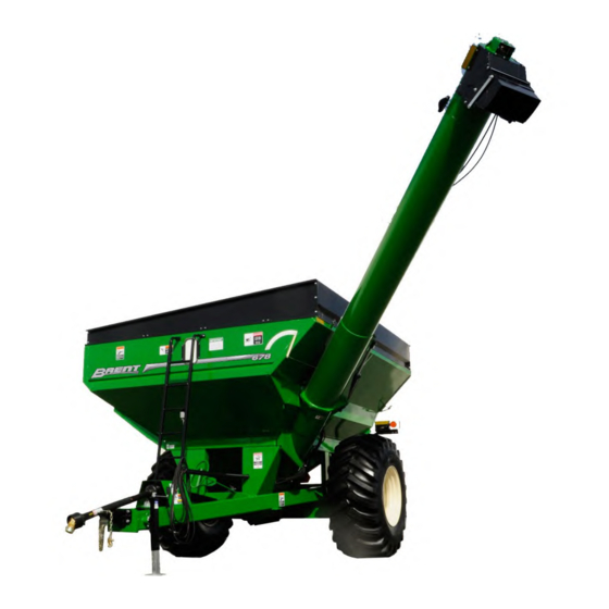
- Page 1 Grain Handling CORNER AUGER GRAIN CART MODELS 678 & 678XL Beginning With Serial Number D10000000 Beginning With Serial Number B22640100 Part No. 251932...
- Page 2 — Introduction Brent 678/678XL Foreword This symbol identifies important safety messages. When you see it, read the message that follows and be alert to the possibility of personal injury. Remember, safety instructions stated in this manual are for your protection. Read them care- fully and follow them closely when working around or using this machine.
-
Page 3: Product Information
The information, specifications, and illustrations in the manual are on the basis of informa- tion available at the time it was written. Due to continuing improvements in the design and manufacture of Unverferth products, all specifications and information contained herein are subject to change without notice. -
Page 4: Table Of Contents
— Introduction Brent 678/678XL Table of Contents Foreward ............................2 Product Information ........................3 Section I Safety General Hazard Information ......................1-2 Safety Decals ..........................1-3 Following Safety Instructions ......................1-4 Before Servicing ..........................1-5 Before Operating ..........................1-5 During Operation ..........................1-6 Before Transporting ......................... - Page 5 — Introduction Brent 678/678XL Table of Contents Section II Set Up Set Up Checklist ........................2-2 General Set Up Information ....................... 2-2 Basic Cart Set Up ....................2-3 through 2-9 Folding Side Extension ......................2-3 SMV Emblem ........................2-4 Lamp Set Up ........................2-5 Drive Line Storage ......................
- Page 6 — Introduction Brent 678/678XL Table of Contents Section III Operation Operating Checklist ........................3-2 Preparing Tractor ........................3-2 Preparing Cart Hardware ..........................3-3 Pivot Pins ..........................3-3 Hitch ............................ 3-3 Auger ........................... 3-3 Hydraulic System ......................... 3-4 Tires/Wheels ......................... 3-4 Drive Shaft Guards ......................
- Page 7 — Introduction Brent 678/678XL Table of Contents Section IV Maintenance Lubrication ............................4-2 Seasonal Storage ..........................4-3 Hub Assembly ..........................4-3 Auger System Lower Auger Disassembly ......................4-4 Lower Auger Assembly ......................4-5 Upper Auger Disassembly......................4-6 Upper Auger Assembly ......................4-7 Upper Auger Assembly Timing ....................
- Page 8 — Introduction Brent 678/678XL Table of Contents Section V Parts PTO Assembly Friction Clutch ....................5-2 PTO Clutch ..........................5-3 Undercarriage ..........................5-4 Touch-Up Paint ........................... 5-5 Auger & Box Components ......................5-6 Decals ............................5-10 Electrical Components ......................5-12 Directional Spout ........................
-
Page 9: Section I
— Safety Brent 678/678XL Section I Safety General Hazard Information ......................1-2 Safety Decals ..........................1-3 Following Safety Instructions ......................1-4 Before Servicing ..........................1-5 Before Operating ..........................1-5 During Operation ..........................1-6 Before Transporting ......................... 1-6 During Transport ..........................1-7 Drive Line Safety .......................... -
Page 10: General Hazard Information
It is true that the designer, the manufacturer, and the safety engineer can help; and they will help, but their combined efforts can be wiped out by a single careless act of the operator. It is said that, “the best kind of a safety device is a careful operator.” We, at Unverferth Mfg. -
Page 11: Safety Decals
— Safety Brent 678/678XL Safety Decals • REPLACE LOST, DAMAgED, PAINTED, OR UNREADAbLE DECALS IMMEDIATELY. IF PARTS THAT HAvE DECALS ARE REPLACED, ALSO MAkE SURE TO INSTALL NEW DECALS. THESE DECALS INFORM AND REMIND THE OPERATOR WITH OPERATIONAL INFORMATION AND SAFETY MESSAgES. -
Page 12: Following Safety Instructions
— Safety Brent 678/678XL Following Safety Instructions • Read and understand this operator’s manual before operating. • All machinery should be operated only by trained and authorized personnel. • To prevent machine damage, use only attachments and service parts approved by the manufacturer. -
Page 13: Before Servicing
— Safety Brent 678/678XL Before Servicing • Avoid working under an implement; however, if it becomes absolutely unavoidable, make sure the implement is safely blocked. • Ensure that all applicable safety decals are installed and legible. • To prevent personal injury or death, always ensure that there are people who remain out- side the cart to assist the person working inside, and that all safe workplace practices are followed. -
Page 14: During Operation
— Safety Brent 678/678XL During Operation • Regulate speed to field conditions. Maintain complete control at all times. • Never service or lubricate equipment when in operation. • Keep away from overhead power lines. Electrical shock can cause serious injury or death. -
Page 15: During Transport
— Safety Brent 678/678XL During Transport • Comply with all laws governing highway safety when moving machinery. • Use transport lights as required by all laws to adequately warn operators of other ve- hicles. • Use good judgment when transporting equipment on highways. -
Page 16: Driveline Safety
— Safety Brent 678/678XL Driveline Safety • Do not allow children near equipment that is running or engaged. • Do not exceed 1000 rpm PTO speed. • Disengage the PTO, stop the tractor engine, and remove key from ignition before making inspections, or performing maintenance and repairs. -
Page 17: Pressurized Oil
— Safety Brent 678/678XL Pressurized Oil • Relieve pressure before disconnecting hydraulic lines from tractor, loosening any hydraulic fittings or servicing hydraulic system. See hydraulic power unit manual for procedure to relieve pressure. • High-pressure fluids can penetrate the skin and cause serious injury or death. -
Page 18: Preparing For Emergencies
— Safety Brent 678/678XL Preparing for Emergencies • Keep a first aid kit and properly rated fire extinguisher nearby. • Keep emergency numbers for fire, rescue, and poison control personnel near the phone. Wearing Protective Equipment • Wear clothing and personal protective equipment appropriate for the job. - Page 19 — Set Up Brent 678/678XL Section II Set Up Set Up Checklist ........................2-2 General Set Up Information ....................... 2-2 Basic Cart Set Up ....................2-3 through 2-9 Folding Side Extension ......................2-3 SMV Emblem ........................2-4 Lamp Set Up ........................2-5 Drive Line Storage ......................
-
Page 20: General Set Up Information
— Set Up Brent 678/678XL Pre-Delivery Checklist After the cart has been completely assembled, use the following checklist and inspect the cart. Check off each item as it is found satisfactory or after proper adjustment is made. o Torque wheel nuts as specified in MAINTENANCE section. -
Page 21: Basic Cart Set Up
— Set Up Brent 678/678XL Basic Set Up Due to shipping requirements and various dealer-installed options, some initial cart Setup will be required after it arrives from the factory. Use the following procedures as needed for initial cart Setup. 233929 Folding Side Extensions 1. -
Page 22: Smv Emblem
— Set Up Brent 678/678XL (continued) Basic Set Up Transport Lighting and Markings Compliance with all lighting and marking laws is the responsibility of the operator at the time of travel. Please see federal regulation 49 CFR 562; available at www.govinfo.gov for US federal law requirements. -
Page 23: Drive Line Storage
— Set Up Brent 678/678XL (continued) Basic Set Up Auger Rest Retainer Removal Remove the retainer located on the upper auger rest at the back of the cart, before folding out the upper auger tube. • Upper auger retainer must be removed before operating upper auger tube. Failure to re- move retainer will result in damage to the upper auger tube. -
Page 24: Ladder Installation
— Set Up Brent 678/678XL Basic Set Up (continued) Ladder Installation Ladder can be found inside the grain cart. Set ladder over mounting lugs and secure to front panel of cart. • to PreVent Personal injury or DEATH, ALWAYS ENSURE THAT THERE... -
Page 25: Wheel/Tire Set Up
— Set Up Brent 678/678XL Basic Set Up (continued) Wheel/Tire Set Up Tire Pressure Tire pressure must be verified before first use and adjusted as necessary. Refer to main- tenance section of this manual for information on tire pressure. Wheel Nuts •... -
Page 26: Directional Spout Installation
— Set Up Brent 678/678XL Basic Set Up (continued) Directional Spout Installation 1. Remove the four 1/4” bolts as shown in Fig. 1. This should allow the chute weldment to pivot on the shipping bracket. 2. Rotate the chute weldment up and align the holes in the chute with the holes on the top of the auger tube. -
Page 27: Optional Adjustable Axle
— Set Up Brent 678/678XL Basic Set Up (continued) Optional Adjustable Axle • tiPPing or MoVeMent of the Machine can cause serious injury or death. bE SURE THE MACHINE IS SECURELY bLOCkED. • falling objects can cause serious injury or death. do not work under THE MACHINE AT ANY TIME WHILE bEINg HOISTED. - Page 28 — Set Up Brent 678/678XL Optional Weather Guard Tarp Installation • falling objects can cause serious injury or death. do not work under the MACHINE AT ANY TIME WHILE bEINg HOISTED. bE SURE ALL LIFTINg DEvICES AND SUP- PORTS ARE RATED FOR THE LOADS bEINg HOISTED. THESE ASSEMbLY INSTRUCTIONS WILL REqUIRE SAFE LIFTINg DEvICES UP TO 250 LbS.
-
Page 29: End Caps, Bows
— Set Up Brent 678/678XL Optional Weather Guard Tarp Installation (continued) End Caps, Bows 1. Install the side board extensions to the box. 2. Assemble the end caps (40) to the front and rear side boards with carriage bolts (43) and nuts (32). Fasten to right and left side boards with self-threading screws (44) See Fig. - Page 30 — Set Up Brent 678/678XL Optional Weather Guard Tarp Installation (continued) 4. Insert the bows (41) into the slots in the Fig. 4 left side board. Retain with carriage bolt (43) and flange nut (30). See Fig. 4. Left-Hand Side of Tarp bow Shown 5.
-
Page 31: Cables, Tarp, Tubes
— Set Up Brent 678/678XL Optional Weather Guard Tarp Installation (continued) Cables, Tarp, Tubes 6. Attach the cable assemblies (902612) to the front end cap (250880B) holes, see Fig. 6. Run cables over the top of the bows (251211B). If applicable, drill holes into the rear sideboard for the cable brackets (281712B) (Fig. - Page 32 — Set Up Brent 678/678XL Optional Weather Guard Tarp Installation (continued) 7. (2-person operation) On a clean floor, lay the tarp out flat with the raw edge of the hems and pockets down and the exterior side facing up. 8. Insert the small 1 1/8” tube (23) by sliding it into the small pocket of the tarp.
- Page 33 — Set Up Brent 678/678XL Optional Weather Guard Tarp Installation (continued) 10. Insert knotted stretch rope (221722) Fig. 8 through flat washer (9405-074), plastic tube (221582) and end plug (9004947). Place these items as an assembly into front end of 2” tube (221576) and press the end plug into the end of the tube.
- Page 34 — Set Up Brent 678/678XL Optional Weather Guard Tarp Installation (continued) 11. Using an appropriate lifting device rated for Fig. 9 a minimum of 250 lbs., position the tarp on top of the left hand side of the cart. Place the 1 1/8”...
- Page 35 — Set Up Brent 678/678XL Optional Weather Guard Tarp Installation (continued) 12. Unroll the tarp and insert stretch cord through the top of the eye bolt (9004548). With the tarp rolled up under the latch plate, leave 2 or 3 inches of slack in the stretch cord and knot below the eyebolt.
-
Page 36: Hand Crank
— Set Up Brent 678/678XL Optional Weather Guard Tarp Installation (continued) Hand Crank 1. Locate the channel bracket holes just above the box fold line, centered on the box. Drill Fig. 12 two 5/16” holes as shown in Fig. 12. -
Page 37: For Scale Information, Please Refer To Your Scale Manual
— Operation Brent 678/678XL Section III Operation Operating Checklist ........................3-2 Preparing Tractor ........................3-2 Preparing Cart Hardware ..........................3-3 Pivot Pins ..........................3-3 Hitch ............................ 3-3 Auger ........................... 3-3 Hydraulic System ......................... 3-4 Tires/Wheels ......................... 3-4 Drive Shaft Guards ......................3-5 Lubrication .......................... -
Page 38: Operating Checklist
— Operation Brent 678/678XL Operating Checklist o Read and understand all safety precautions before operating cart. Check axle spacing to be sure axle is adjusted from shipping position to desired operat- ing width. (If Applicable) Check to be sure all the reflective decals and the SMV sign are clearly visible with the cart attached to the tractor. -
Page 39: Preparing Cart
— Operation Brent 678/678XL Preparing Cart Perform the service checks as outlined below. Repair or replace any damaged or worn parts before operating. Hardware Check for loose bolts and nuts, and tighten as needed. Check again after the first half-day of operation. -
Page 40: Hydraulic System
— Operation Brent 678/678XL Preparing Cart (continued) Hydraulic System Check all hoses and cylinders for signs of leakage. Hoses should not be kinked, twisted or rubbing against sharp edges. Re-route or repair hoses as necessary. Refer to SAFETY section for additional information on safe repair and inspection of hydraulic components. -
Page 41: Drive Shaft Guards
— Operation Brent 678/678XL Preparing Cart (continued) Drive Shaft Guards The PTO driveshaft shield, floating guard tube Fig. 2 and U-joint guard are factory installed. Make sure they are in place before operating the auger. Fig. 3 Lubrication Lubricate the cart as outlined in the MAINTENANCE section of this manual. -
Page 42: Hitching To Tractor Drawbar Connection
— Operation Brent 678/678XL Hitching to Tractor Drawbar Connection This cart is intended to be hitched to a tractor drawbar. Do not attempt to hitch to any other location on the tractor other than the drawbar. The cart is equipped standard with a single tang hitch. -
Page 43: Jack Usage
— Operation Brent 678/678XL Hitching to Tractor (continued) Jack Usage • unhitching a loaded cart can cause serious injury or death due to THE TONgUE RISINg OR FALLINg. ALWAYS HAvE A LOADED CART ATTACHED TO A TRACTOR. THE JACk IS INTENDED TO SUPPORT AN EMPTY CART ONLY. -
Page 44: Transport Chain Connection
— Operation Brent 678/678XL Hitching to Tractor (continued) Transport Chain Connection • always use transPort chain when transPorting iMPleMents. failure to USE A TRANSPORT CHAIN COULD CAUSE PERSONAL INJURY IF CART bECOMES DISENgAgED. Always use intermediate chain support when Fig. 6 connecting the grain cart directly to a tractor. -
Page 45: Hydraulic Connections For Hydraulic Drive
— Operation Brent 678/678XL Hitching to Tractor (continued) Clean hydraulic hose couplers before connecting to the tractor. For convenience, it is recom- mended to connect the flow door circuit hoses to tractor implement coupler #1, auger spout circuit hoses to coupler #2, and attach auger fold circuit to coupler #3. -
Page 46: Electrical Connections
— Operation Brent 678/678XL Hitching to Tractor (continued) Electrical Connections This cart is equipped with a seven-pin SAE con- nector plug which will connect with the receptacle found on most newer tractors. If your tractor does not have this type of receptacle, an SAE J-560 seven-point socket can be purchased from your Brent dealer (Part number 92824). -
Page 47: Towing
— Operation Brent 678/678XL Towing This cart is not equipped with brakes. Ensure that the towing vehicle has adequate weight and braking capacity to tow this implement. See the tractor operator’s manual for towing capacity. Never tow a loaded grain cart over public roads. -
Page 48: Auger Operation Pto Driven Auger
— Operation Brent 678/678XL Auger Operation PTO Driven Auger • electrocution will cause serious injury or death. the gRAIN CART IS NOT INSULATED. kEEP AWAY FROM ALL ELECTRI- CAL LINES AND DEvICES. ELECTROCUTION CAN OCCUR WITHOUT DIRECT CONTACT. • entangleMent with the driVeline will cause serious injury or death. -
Page 49: Optional Equipment Hydraulic Drive
— Operation Brent 678/678XL Optional Equipment Hydraulic Drive The optional hydraulically-driven auger permits Fig. 9 cart operation using tractors that are not equipped with a PTO. However, due to the power requirements of a grain cart, it should be expected that a hydraulically-driven grain cart will not unload as quickly as a PTO driven cart. - Page 50 — Operation Brent 678/678XL Optional Equipment (continued) Hydraulic Drive (continued) NOTE: For complete assembly and operation details for the Hydraulic Drive, please refer to the Hydraulic Drive manual (282894). 1. Before loading cart or operating auger, verify that the flow control door is closed.
- Page 51 — Operation Brent 678/678XL Tarp Operating Safety Information • to PreVent Personal injury or death, do not allow anyone on a closed TARP. TARP SYSTEM IS NOT DESIgNED TO SUPPORT A PERSON. • falling objects can cause serious injury or death. reMoVe accuMulated water/snow/ice or any other objects froM tarP before oPening tarP.
-
Page 52: Weather Guard Tarp
— Operation Brent 678/678XL Weather Guard Tarp Always use adequate caution when operating tarp. If tarp is covered with snow, it is important to remove snow before operating. End caps must be free from grain that may be piled on them. Grain should not be heaped higher than end caps. - Page 53 — Maintenance Brent 678/678XL Section IV Maintenance Lubrication ............................4-2 Seasonal Storage ..........................4-3 Hub Assembly ..........................4-3 Auger System Lower Auger Disassembly ......................4-4 Lower Auger Assembly ......................4-5 Upper Auger Disassembly......................4-6 Upper Auger Assembly ......................4-7 Upper Auger Assembly Timing ....................4-8 Auger Flow Door Cylinder Replacement ..................
-
Page 54: Lubrication
— Maintenance Brent 678/678XL Lubrication To keep your grain cart in top operating condition and to assure its proper performance and reliability for a long period of time, periodic inspection and lubrication is a must. Fig. 1 Fig. 2... -
Page 55: Seasonal Storage
— Maintenance Brent 678/678XL Seasonal Storage Your cart is an important investment. Spend a little time to protect it from destructive rust and corrosion, You will be repaid in longer service life and better performance. Do the following before placing the cart in storage: 1. -
Page 56: Auger System
— Maintenance Brent 678/678XL Auger System • turning auger and other MoVing Parts can crush and CUT. DISENgAgE PTO AND SHUT-OFF ENgINE bEFORE SERvICINg MACHINE OR ENTERINg gRAIN TANk, OR OPENINg CLEAN-OUT DOOR(S). • falling objects can cause serious injury or death. do not work under THE MACHINE AT ANY TIME WHILE bEINg HOISTED. -
Page 57: Lower Auger Assembly
— Maintenance Brent 678/678XL Auger System (continued) Lower Auger Assembly 1. Assemble drive dog (1) and hanger bearing (2) to auger and secure with two 5/8” x 6” capscrews (7), lock washers and nuts (8). 2. Install auger, drive dog, and hanger bearing into lower housing and secure with three 3/8”... -
Page 58: Upper Auger Disassembly
— Maintenance Brent 678/678XL Auger System (continued) Upper Auger Disassembly 1. Support the upper auger assembly with a 2 ton hoist and two 1000 lb. straps. 2. Remove auger tube cylinder pin and carefully swing cylinder down without breaking hose connections. -
Page 59: Upper Auger Assembly
— Maintenance Brent 678/678XL Auger System (continued) Upper Auger Assembly 1. Install upper bearing and spring assembly if previously removed. 2. Using a safe lifting device rated for 600 lbs., insert auger in auger tube. Back out bear- ing setscrews and insert auger stub shaft through bearing. Retain auger with 5/16” x 2”... - Page 60 — Maintenance Brent 678/678XL Auger System (continued) Upper Auger Assembly Timing Fully extend the upper auger and rotate the auger assembly to ensure both lower & upper augers are engaged. allow the auger assembly to stop completely, then lower the upper auger approximately 45 degrees, shut off the tractor, remove the keys from the ignition.
-
Page 61: Auger Flow Door Cylinder Replacement
— Maintenance Brent 678/678XL Auger System (continued) Auger Flow Door Cylinder Replacement • neVer enter cart with auger or tractor running. serious or fatal in- JURY CAN OCCUR DUE TO ENTANgLEMENT WITH ROTATINg COMPONENTS. ALWAYS STOP ENgINE AND REMOvE kEY bEFORE ENTERINg CART. - Page 62 — Maintenance Brent 678/678XL Auger System (continued) Auger Flow Door Cylinder Replacement (continued) 2. On the inside of the cart, open the screen service access panel shown in Fig. 21. Screen Service Access Panel FIG. 21 3. Remove the cotter pins from the lower cylinder pin then remove the pin, shown in Fig.
- Page 63 — Maintenance Brent 678/678XL Auger System (continued) Auger Flow Door Cylinder Replacement (continued) 6. Label the hydraulic hoses to indicate up- FIg. 23 per and lower. Disconnect them from the cylinder (Fig. 23). Remove Upper Hose 7. Remove the cotter pins from the upper cylinder pin and remove pin (Fig.
-
Page 64: Verify Telescoping Pto Shaft Length
— Maintenance Brent 678/678XL Verify Telescoping PTO Shaft Length • ProPerly eXtended and collaPsed lengths of the telescoPing Pto shaft MUST bE vERIFIED bEFORE FIRST OPERATION WITH EACH AND EvERY DIFFERENT TRACTOR. IF THE EXTENDED LENgTH OF THE PTO SHAFT IS NOT SUFFICIENT, IT... - Page 65 — Maintenance Brent 678/678XL Verify Telescoping PTO Shaft Length (continued) 4. Hitch tractor drawbar to cart, ensuring that tractor and cart are on level ground and coupled as straight as practical. 5. Connect PTO shaft to tractor, and measure length “L” from same points as used in step 1. Ensure that this measurement does not exceed the maximum recommended extended length calculated in step 3 above.
-
Page 66: Pto Shaft And Clutch
— Maintenance Brent 678/678XL PTO Shaft and Clutch Lubrication (Figs. D1 - D6) Lubricate with quality grease before starting work and every 8 operating hours. Clean and grease PTO driveshaft before each prolonged period of non-use. Molded nipples on the... - Page 67 — Maintenance Brent 678/678XL PTO Shaft and Clutch (continued) Length Adjustment (Figs. F1 - F4) NOTE: Maximum operating length LB. 1. To adjust length, hold the half-shafts next to each other in the shortest working position and mark them. 2. Shorten inner and outer guard tubes equally.
- Page 68 — Maintenance Brent 678/678XL PTO Shaft and Clutch (continued) To Dismantle Guard (Figs. J1 - J4) 1. Remove locking screw. 2. Align bearing tabs with cone pockets. 3. Remove half-guard. 4. Remove bearing ring. To Assemble Guard (Figs. K1 - K5) 1.
-
Page 69: Pto Quick Disconnect
— Maintenance Brent 678/678XL PTO Shaft and Clutch (continued) To Assemble Cone (Figs. L1 - L3) 1. Dismantle guard (Fig. L1 - L3). Remove the old cone (e.g. cut open with knife). Take off chain. Place the neck of the new cone in hot water (approx. - Page 70 — Maintenance Brent 678/678XL PTO Quick Disconnect (continued) Quick Disconnect Disassembly 1. Compression Spring 2. Ball 3. Lock Collar 4. Back-up ring 5. Snap ring * Back-up ring * For some clutch types, place additional back up ring first. Compress lock collar (#3) and remove snap ring (#5).
- Page 71 — Maintenance Brent 678/678XL PTO Quick Disconnect (continued) Clutch Disassembly Tighten the four hex nuts (12) uniformly until the clutch pack and hub are loose. Use special tool 9002007 to bend all four retaining lugs back on the edge of the clutch housing. Remove the thrust plate with Belleville springs to get at the friction disks, drive plates and hub for inspection and service.
- Page 72 — Maintenance Brent 678/678XL Weather Guard Tarp Troubleshooting PRObAbLE CAUSE CORRECTION Tarp sags in middle areas Bows may be bent or adjusted too low. Missing or loose ridge strap. Replace or retighten. U-joint may need to be adjusted on splinded shaft to provide more tension.
-
Page 73: Electrical System Schematic
— Maintenance Brent 678/678XL Electrical System Schematic GRAIN CART WIRES White -- Ground Green -- Right amber flashing lamp Yellow -- Left amber flashing lamp Brown -- Tail light Black -- Interior & Auger Lights Red -- Brake Lights 220912... -
Page 74: Hydraulic System Schematic
— Maintenance Brent 678/678XL Hydraulic System Schematic 4-22... -
Page 75: Wheels And Tires Wheel Nut Torque Requirements
— Maintenance Brent 678/678XL Wheels and Tires Wheel Nut Torque Requirements • iMProPerly torQued wheel nuts/bolts can cause a loss of iMPleMent control and Machine daMage. torQue wheel nuts/bolts to Values in TAbLE. CHECk TORqUE bEFORE USE, AFTER ONE HOUR OF UNLOADED USE OR after first load, and each load until wheel nuts/bolts Maintain torQue vALUE. -
Page 76: Tire Pressure
— Maintenance Brent 678/678XL Wheel Torque Chart & Tire Specifications (Continued) Tire Pressure The following is to be used as a general guide for tire inflation and figures can vary depending It is important that tires are inspected after unit is on specific brand of tire used. - Page 77 — Maintenance Brent 678/678XL Wheel Torque Chart & Tire Specifications (Continued) Tire Pressure (continued) Tire Pressure for Grain Carts Load Index / Ply Tire Make Part Number Tire Size Max. PSI Rating Titan/Goodyear 94286 23.1x26 R-3 99364 23.1x26 R-1 99307 24.5R32 R-1...
-
Page 78: Tire Warranty
— Maintenance Brent 678/678XL Wheels and Tires (continued) Tire Warranty For questions regarding new tire warranty, please contact your local original equipment tire dealer. USED TIRES CARRY NO WARRANTY. Following are phone numbers and Websites for your convenience: Firestone www.firestoneag.com... - Page 79 — Maintenance Brent 678/678XL Complete Torque Chart Capscrews - Grade 5 NOTE: • Grade 5 capscrews can be identified by three radial dashes on the head. • For wheel torque requirements, refer to Wheels and Tires. • Tighten U-bolts evenly and equally to have the same number of threads exposed on each end.
- Page 80 — Maintenance Brent 678/678XL Complete Torque Chart Capscrews - Grade 8 NOTE: • Grade 8 capscrews can be identified by six radial dashes on the head. • For wheel torque requirements, refer to Wheels and Tires. • Tighten U-bolts evenly and equally to have the same number of threads exposed on each end.
-
Page 81: Hydraulic Fittings
— Maintenance Brent 678/678XL Hydraulic Fittings – Torque and Installation SAE FLARE CONNECTION (J. 1. Tighten nut with finger until it bottoms the seat. 2. Using a wrench, rotate nut to tighten. Turn nut 1/3 turn to apply proper torque. - Page 82 — Maintenance Brent 678/678XL Notes 4-30...
- Page 83 — Parts Brent 678/678XL Section V Parts PTO Assembly Friction Clutch ....................5-2 PTO Clutch ..........................5-3 Undercarriage ..........................5-4 Touch-Up Paint ........................... 5-5 Auger & Box Components ......................5-6 Decals ............................5-10 Electrical Components ......................5-12 Directional Spout ........................5-14 Side Boards..........................
-
Page 84: Pto Assembly Friction Clutch
— Parts Brent 678/678XL PTO Assembly Friction Clutch Please visit www.unverferth.com/parts/ for the most current parts listing. 250928 ITEM DESCRIPTION PART NO. QTY. NOTES PTO Shaft w/ Shielding 94868 1 3/4-20 Spline PTO Shaft w/ Shielding 95214 1 3/8-21 Spline... -
Page 85: Pto Clutch
— Parts Brent 678/678XL PTO Clutch Please visit www.unverferth.com/parts/ for the most current parts listing. ITEM DESCRIPTION PART NO. QTY. NOTES Clutch Complete 94838 Includes Items 7-17 Nut, M8 DIN 6330 Hex 92386 Belleville Spring (Red dot) 93815 Thrust Plate... -
Page 86: Undercarriage
— Parts Brent 678/678XL Undercarriage Please visit www.unverferth.com/parts/ for the most current parts listing. ITEM DESCRIPTION PART NO. QTY. NOTES Capscrew, 3/4”-10UNC x 2 1/4” G5 9390-146 Capscrew, 1”-8UNC x 6” G5 9390-195 Capscrew, 1”-8UNC x 7” G5 9390-197 Hex Nut, 1”-8UNC 9394-020 Lock Washer, 3/4"... -
Page 87: Touch-Up Paint
— Parts Brent 678/678XL Undercarriage Please visit www.unverferth.com/parts/ for the most current parts listing. ITEM DESCRIPTION PART NO. QTY. NOTES Retaining Ring, 1” 91192 Weigh Bar - 2 1/2" Dia. 9004902 Wheel Nut, 3/4”-16UNF G8 92458 Scale Hitch, Clevis 200004B... -
Page 88: Auger & Box Components
— Parts Brent 678/678XL Auger & Box Components Please visit www.unverferth.com/parts/ for the most current parts listing. - Page 89 — Parts Brent 678/678XL Auger & Box Components Please visit www.unverferth.com/parts/ for the most current parts listing. ITEM DESCRIPTION PART NO. NOTES Upper Auger Flighting 265130B For Model 678 Upper Auger Flighting 2005411B For Model 678XL Upper Auger Housing =Green=...
- Page 90 — Parts Brent 678/678XL Auger & Box Components (continued) Please visit www.unverferth.com/parts/ for the most current parts listing. ITEM DESCRIPTION PART NO. NOTES Hose Marker Sleeve, Auger Raised (Green) 9003997 Hose Marker Sleeve, Auger Lower (Green) 9003998 Indicator Needle 250464W...
- Page 91 — Parts Brent 678/678XL Notes Please visit www.unverferth.com/parts/ for the most current parts listing.
-
Page 92: Decals
— Parts Brent 678/678XL Decals Please visit www.unverferth.com/parts/ for the most current parts listing. 5-10... - Page 93 — Parts Brent 678/678XL Decals Please visit www.unverferth.com/parts/ for the most current parts listing. ITEM DESCRIPTION PART NO. QTY. NOTES Indicator Needle =Beige= 250464W Decal, Hitch Torque 9001708 Reflector =Amber= 9003127 Decal, DANGER “Electrical” 9003474 Decal, WARNING “No Riders” 9003476 Decal, DANGER “Rotating or Moving Parts”...
-
Page 94: Electrical Components
— Parts Brent 678/678XL Electrical Components Please visit www.unverferth.com/parts/ for the most current parts listing. 5-12... - Page 95 — Parts Brent 678/678XL Electrical Components Please visit www.unverferth.com/parts/ for the most current parts listing. ITEMS DESCRIPTION PART NO. NOTES Wiring Harness, Rear 9003510 Wiring Harness, Front 9003509 Electrical Coupler 92450 Wiring Harness, Auger 9004350 Auger Light 9500807 Connector, Male 9004140 Connector 1/2”...
-
Page 96: Directional Spout
— Parts Brent 678/678XL Directional Spout Please visit www.unverferth.com/parts/ for the most current parts listing. ITEM DESCRIPTION PART NO. QTY. NOTES Hood Assembly 281375 Hood 281376B Upper Deflector 281377B Lower Deflector 281378B Pivot Shaft 281390 Pivot Shaft 281389 281368 Bushing... -
Page 97: Side Boards
— Parts Brent 678/678XL Side Boards Please visit www.unverferth.com/parts/ for the most current parts listing. ITEM DESCRIPTION PART NO. QTY. NOTES Front Board 280305B 18" to 5" Tall Rear Board 280306B 18" to 5" Tall Left Front Side Board 250874B 18"... -
Page 98: Lower Auger And Driveline
— Parts Brent 678/678XL Lower Auger And Driveline Please visit www.unverferth.com/parts/ for the most current parts listing. ITEM DESCRIPTION PART NO. QTY. NOTES Drive Dog Weldment 28977 Auger Bushing Assembly 265132B Bronze Bearing 2.515 ID 9001198 Grease Zerk, 90° 9000875... -
Page 99: Driveline U-Joint Assembly
— Parts Brent 678/678XL Driveline U-Joint Assembly Please visit www.unverferth.com/parts/ for the most current parts listing. ITEM DESCRIPTION PART NO. QTY. NOTES Complete U-Joint Assembly 95012 Yoke 95010 Grease Zerk, 1/4-28UNF 91160 Yoke, 1 3/8-6 Spline 95011 Quick-Disconnect Pin Kit 92362 Cross &... -
Page 100: Hub
— Parts Brent 678/678XL Please visit www.unverferth.com/parts/ for the most current parts listing. ITEM DESCRIPTION PART NO. QTY. NOTES Complete Hub Assembly =Green= 200079G Includes Items 1-6 & 10-14 Complete Hub Assembly =Red= 200079R Includes Items 1-6 & 10-14 Seal, 3 11/16" ID... -
Page 101: Hub - Dual Wheels
— Parts Brent 678/678XL Hub - Dual Wheels Please visit www.unverferth.com/parts/ for the most current parts listing. ITEM DESCRIPTION PART NO. QTY. NOTES Complete Hub Assembly =Green= 266456G Includes Items 1-8 & 16 Complete Hub Assembly =Red= 266456R Includes Items 1-8 & 16 Seal, 3 11/16"... -
Page 102: Adjustable Axle - 120
— Parts Brent 678/678XL Adjustable Axle — 120" Please visit www.unverferth.com/parts/ for the most current parts listing. 5-20... - Page 103 — Parts Brent 678/678XL Adjustable Axle — 120" Please visit www.unverferth.com/parts/ for the most current parts listing. ITEM DESCRIPTION PART NO. QTY. NOTES Adjustable Axle Assembly =Green= 250640G Includes Items 1 thru 9 Adjustable Axle Assembly =Red= 250640R Axle Weldment =Green=...
-
Page 104: 45° Gearbox
— Parts Brent 678/678XL 45° Gearbox Please visit www.unverferth.com/parts/ for the most current parts listing. ITEM DESCRIPTION PART NO. QTY. NOTES Gearbox, Complete 9002812 Incl. Items 1-17 Shaft, Input 9001131 1.8:1 Gear Shaft, Output 9001132 1.8:1 Gear Bearing Cone 92697... -
Page 105: Auger Cylinder
— Parts Brent 678/678XL Auger Cylinder Please visit www.unverferth.com/parts/ for the most current parts listing. ITEM DESCRIPTION PART NO. QTY. NOTES 3 x 20" Cylinder, Complete 9003103 Seal Kit 9003772 Flow Control Door Cylinder ITEM DESCRIPTION PART NO. QTY. NOTES 2 x 36"... -
Page 106: Optional Hydraulic Pto Drive (Up To 55Gpm) Kit #280207
— Parts Brent 678/678XL Optional Hydraulic PTO Drive (Up To 55GPM) Kit #280207 Please visit www.unverferth.com/parts/ for the most current parts listing. 5-24... - Page 107 — Parts Brent 678/678XL Optional Hydraulic PTO Drive (Up To 55GPM) Kit #280207 Please visit www.unverferth.com/parts/ for the most current parts listing. ITEM DESCRIPTION PART NO. QTY. NOTES Hydraulic Drive Kit 280207 Motor Mount Weldment =Black= 280066B Pressure Gauge (3000 PSI)
-
Page 108: Optional Weather Guard Tarp
— Parts Brent 678/678XL Optional Weather Guard Tarp Please visit www.unverferth.com/parts/ for the most current parts listing. ITEM PART NO. DESCRIPTION NOTES 221642 Tarp Kit with End Caps - Model 678 221576 Roll Tube Weldment 221579 Fixed Tube Weldment 221582 Pipe - 132”... - Page 109 — Parts Brent 678/678XL Optional Weather Guard Tarp Please visit www.unverferth.com/parts/ for the most current parts listing. ITEM PART NO. DESCRIPTION NOTES 2006091 Rear Plate - Latch 81 1/2” 2006092 Front Plate - Latch 81 1/2” 251132B Channel Bracket 35 3/4" Long 221721 Bungee 3/8”...
- Page 110 L:\PAGemAKeR_Om_FILeS\OmSheLLROCK\CART\678////DeCemBeR 2012-7//mARCh 2013-8//mARCh 2014-9//DeCemBeR 2014-10//mARCh 2016-11//June 2017-12//JuLy 2018-13//mARCh 2020-15//AuGuST 2022-16...
Need help?
Do you have a question about the BRENT 678 and is the answer not in the manual?
Questions and answers