Table of Contents
Advertisement
Quick Links
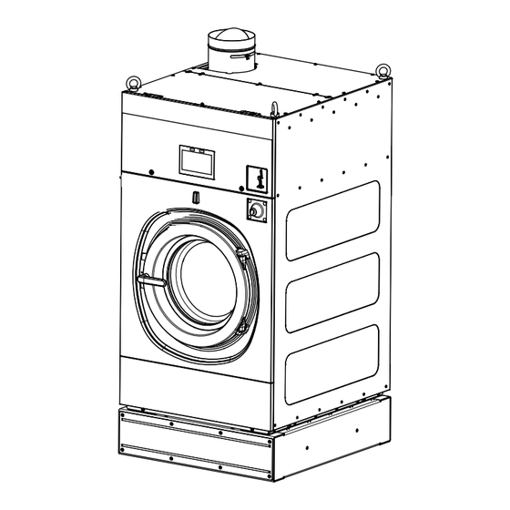
SQ Combo Wash and Dry
Cabinet Freestanding
Refer to Page 13 for Model Identification
Original Instructions
Keep These Instructions for Future Reference.
CAUTION: Read the instructions before using the machine.
(If this machine changes ownership, this manual must accompany machine.)
Part No. D2701EN
www.alliancelaundry.com
July 2024
Advertisement
Table of Contents

Subscribe to Our Youtube Channel
Related Manuals for Alliance Laundry Systems WC135B


Summary of Contents for Alliance Laundry Systems WC135B
- Page 1 SQ Combo Wash and Dry Cabinet Freestanding Refer to Page 13 for Model Identification Original Instructions Keep These Instructions for Future Reference. CAUTION: Read the instructions before using the machine. (If this machine changes ownership, this manual must accompany machine.) Part No.
-
Page 3: Table Of Contents
Input Voltage Requirements................41 © Copyright 2024, Alliance Laundry Systems LLC All rights reserved. No part of the contents of this book may be reproduced or transmitted in any form or by any means without the expressed written consent of the publisher. - Page 4 Care of Stainless Steel................... 61 Gas Valves....................61 Recommended Spare Parts................61 Disposal of Unit..................63 Disconnecting the Machine................63 Disposal of Unit....................63 China Restriction of hazardous substances (RoHS)....... 64 © Copyright, Alliance Laundry Systems LLC - Part No. D2701EN DO NOT COPY or TRANSMIT...
-
Page 5: Explanation Of Safety Instruction Messages
NOTE: The word “NOTE” is used to communicate in- stallation, operation, maintenance or servicing informa- tion that is important but not hazard related. © Copyright, Alliance Laundry Systems LLC - Part No. D2701EN DO NOT COPY or TRANSMIT... -
Page 6: Important Safety Instructions
The bolts must be tightened by means of torgue wrench. © Copyright, Alliance Laundry Systems LLC - Part No. D2701EN DO NOT COPY or TRANSMIT... - Page 7 See Install instruction for safely remove them. Sharp edges can cause personal injury. Wear safety glasses and gloves, use proper tools and provide lighting when handling sheet metal parts. © Copyright, Alliance Laundry Systems LLC - Part No. D2701EN DO NOT COPY or TRANSMIT...
- Page 8 Cleaning and maintenance shall not be made by chil- tion with a locking system in the isolated position dren. shall be provided. Operation Prevention © Copyright, Alliance Laundry Systems LLC - Part No. D2701EN DO NOT COPY or TRANSMIT...
- Page 9 Before open the door makes sure that the basket is com- pletely stopped and the water has drained. Injury Prevention © Copyright, Alliance Laundry Systems LLC - Part No. D2701EN DO NOT COPY or TRANSMIT...
- Page 10 Do not force discharge, recharge, disas- semble, heat above 158⁰F [70⁰C] or incinerate. Do- ing so may result in injury due to venting, leakage or explosion resulting in chemical burns. © Copyright, Alliance Laundry Systems LLC - Part No. D2701EN DO NOT COPY or TRANSMIT...
- Page 11 • Always contact your dealer, distributor, service must be maintained. agent or the manufacturer on any problems or conditions you do not understand. Electronic control: © Copyright, Alliance Laundry Systems LLC - Part No. D2701EN DO NOT COPY or TRANSMIT...
- Page 12 Internal Chemical Burns in as little as 2 hours. contact the source from which the machine was pur- • KEEP new and used batteries OUT OF REACH of chased or contact Alliance Laundry Systems at +1 CHILDREN. (920) 748-3950 for the name and address of the nearest •...
-
Page 13: Model Identification
HZA240 IZX135 IZX240 IZC135 IZC240 IZA135 IZA240 UZX135 UZX240 UZC135 UZC240 UZA135 UZA240 PZX135 PZX240 PZC135 PZC240 PZA135 PZA240 NZX135 NZX240 NZC135 NZC240 NZA135 NZA240 © Copyright, Alliance Laundry Systems LLC - Part No. D2701EN DO NOT COPY or TRANSMIT... -
Page 14: Regulatory Statements
PRODUCT COMPLIANCE Users of this product are cautioned not to make modifications or changes that are not approved by Alliance Laundry Systems, LLC. Doing so may void the compliance of this product with ap- plicable laws and regulatory requirements and may result in the loss of the user’s authority to operate the equipment. -
Page 15: Introduction
Manufacturing Date - Year Year Serial Number Character 2020 2021 2022 2023 2024 2025 2026 Table 1 © Copyright, Alliance Laundry Systems LLC - Part No. D2701EN DO NOT COPY or TRANSMIT... -
Page 16: Specifications And Dimensions
Height of door bottom above floor, in. 21,26 [540] 26,57 [675] [mm] Without base frame, in. [mm] 13,38 [340] 18,70 [475] Power Supply Electricity 1ph 200-240V ~ 50/60Hz Table continues... © Copyright, Alliance Laundry Systems LLC - Part No. D2701EN DO NOT COPY or TRANSMIT... - Page 17 719 [3,2] 1191 [5,3] [kN] Maximum dynamic load on floor, lbs. 607±112 [2,7±0,5] 1034±112 [4,6±1,1] [kN] Frequency of dynamic load, Hz 17,9 16,3 Table continues... © Copyright, Alliance Laundry Systems LLC - Part No. D2701EN DO NOT COPY or TRANSMIT...
- Page 18 (40% cotton / 60% synthetic) - final residual cycle with casual laundry composition of linen (40% cotton / moisture <10%. 60% synthetic) with satisfactory results - expected residual mois- ture ~ 15%. © Copyright, Alliance Laundry Systems LLC - Part No. D2701EN DO NOT COPY or TRANSMIT...
-
Page 19: Machine Dimensions
13kg / 135l 24kg / 240l Specification models, mm models, mm Specification models, mm models, mm 1615 1835 1050 Table 3 continues... Table 3 continues... © Copyright, Alliance Laundry Systems LLC - Part No. D2701EN DO NOT COPY or TRANSMIT... - Page 20 228 for AU/NZ models models 1360 1580 28,5 28,5 1520 1742,5 257,5 262,5 357,5 362,5 1216 1434 387,5 1113 1315 288,5 308,5 72,5 142,5 Table 3 © Copyright, Alliance Laundry Systems LLC - Part No. D2701EN DO NOT COPY or TRANSMIT...
-
Page 21: Mounting Bolt Hole Locations
Specifications and Dimensions Mounting Bolt Hole Locations CZW159N Figure 3 © Copyright, Alliance Laundry Systems LLC - Part No. D2701EN DO NOT COPY or TRANSMIT... - Page 22 Dimensions in Table 4 are valid also for machines without base frame except the difference between holes diameter “J”. Ma- chines without base frame have holes 4xØ14 (front and rear) + 2xØ16 (middle). © Copyright, Alliance Laundry Systems LLC - Part No. D2701EN DO NOT COPY or TRANSMIT...
-
Page 23: Floor Mounting Layout
6. At least 60 mm recommended for seamless opening of control panel. *Machine base frames have bigger layout dimensions, which en- sure minimal gaps between machine side covers. © Copyright, Alliance Laundry Systems LLC - Part No. D2701EN DO NOT COPY or TRANSMIT... -
Page 24: Installation
© Copyright, Alliance Laundry Systems LLC - Part No. D2701EN DO NOT COPY or TRANSMIT... -
Page 25: Handling, Transport And Storage
3. Handle the machine carefully with a forklift, with a hand pal- let truck or with the help of transport eyes (see chapter be- low). © Copyright, Alliance Laundry Systems LLC - Part No. D2701EN DO NOT COPY or TRANSMIT... -
Page 26: Machine Positioning
7. Recheck the setting of the safety switch, refer to Every 6 Months. CZW190N Figure 6 Machine Positioning Carrying Capacity of the Floor © Copyright, Alliance Laundry Systems LLC - Part No. D2701EN DO NOT COPY or TRANSMIT... -
Page 27: Mounting Bolt Installation
5. Anchor Body 6. Mount leveling legs. 6. Floor 7. Level machine with feet of the machine. Figure 7 © Copyright, Alliance Laundry Systems LLC - Part No. D2701EN DO NOT COPY or TRANSMIT... - Page 28 NOTE: After leveling is complete, tighten the nut se- curely against the machine's base. Refer to Figure 8 . CFD1208N 1. Machine 2. Nut 3. Leveling Leg Figure 8 © Copyright, Alliance Laundry Systems LLC - Part No. D2701EN DO NOT COPY or TRANSMIT...
-
Page 29: Shipping Brace Removal
3. Remove both rear transport holders. IMPORTANT: The machine may not be moved with the shipping braces removed. Save the shipping braces for future use. © Copyright, Alliance Laundry Systems LLC - Part No. D2701EN DO NOT COPY or TRANSMIT... -
Page 30: Panel Reinstallation
All models - 1. 4 connection screws are prepared at the place of installation of the chimney. © Copyright, Alliance Laundry Systems LLC - Part No. D2701EN DO NOT COPY or TRANSMIT... - Page 31 4 screws to the rear upper panel of the machine (the part must be sufficiently pushed into the seal on the perimeter of the chimney). © Copyright, Alliance Laundry Systems LLC - Part No. D2701EN DO NOT COPY or TRANSMIT...
- Page 32 / New Zealand is equipped with an adapter to reduce its connection diameter to Ø148 mm (legal requirements). This has no effect on the instruction described above. © Copyright, Alliance Laundry Systems LLC - Part No. D2701EN DO NOT COPY or TRANSMIT...
-
Page 33: Machine Installation
(refer to General Specifications), and it must allow the machine to be seated in a perfectly level manner. Drain Connection CZW162N 1. Drain connection Figure 16 © Copyright, Alliance Laundry Systems LLC - Part No. D2701EN DO NOT COPY or TRANSMIT... -
Page 34: Drain Valve
Requirement on the drainpipe, the diameter of the tube or the width of the waste channel must increase. Refer to Figure 18 . Table continues... © Copyright, Alliance Laundry Systems LLC - Part No. D2701EN DO NOT COPY or TRANSMIT... -
Page 35: Water Connection Requirements
© Copyright, Alliance Laundry Systems LLC - Part No. D2701EN DO NOT COPY or TRANSMIT... - Page 36 Suitable air cushions (risers) should be installed in supply lines to 2. Hot Water Inlet prevent “hammering.” Alliance Laundry Systems, LLC ranges of front loading commer- Figure 20 cial clothes washing machines have solenoid valves at the inlets. The machines are supplied with approved inlet hoses.
-
Page 37: Connecting Hoses
Refer to serial plate for electrical ratings information use bigger cables to reduce the voltage drop. specific to your machine. © Copyright, Alliance Laundry Systems LLC - Part No. D2701EN DO NOT COPY or TRANSMIT... - Page 38 6. Phases / Neutral conductors 7. Protective conductor 8. Incoming Field Wiring Terminal Figure 22 IMPORTANT: Alliance Laundry Systems warranty does not cover components that fail as a result of improper input voltage. © Copyright, Alliance Laundry Systems LLC - Part No.
-
Page 39: Residual Current Device (Rcd)
4. Phase conductor (if used) conductor must be longer so it can be routed to the machine 5. Molded tube without tension. 6. Stripped length of conductors Figure 23 © Copyright, Alliance Laundry Systems LLC - Part No. D2701EN DO NOT COPY or TRANSMIT... -
Page 40: Machine Protective Earth Connection And Equipotential Bonding
(refer to Table 1). However, for the protection purposes, with the supply cable cross section of a min. 4 mm , select a larger conductor section, i.e., 6 © Copyright, Alliance Laundry Systems LLC - Part No. D2701EN DO NOT COPY or TRANSMIT... -
Page 41: Input Power Conditioning
Single-phase machines require a single-phase inverse-time circuit breaker. Three-phase machines require a separate, three-phase in- verse-time circuit breaker to prevent damage to the motor by dis- © Copyright, Alliance Laundry Systems LLC - Part No. D2701EN DO NOT COPY or TRANSMIT... -
Page 42: Single-Phase Connections
For voltage supply systems with- out neutral, N is replaced by L2. Electrical Machine's Electrical Connection Service Wire Terminal L/L1 (option) Neutral/L2 L2/N N/L2 (option) Table 12 continues... © Copyright, Alliance Laundry Systems LLC - Part No. D2701EN DO NOT COPY or TRANSMIT... -
Page 43: Three-Phase Connections
The factory setting for the drain valve is 50Hz. Figure 27 If the frequency required at installation is 60Hz, redirect the volt- age wire to the appropriate frequency terminal at the drain valve. © Copyright, Alliance Laundry Systems LLC - Part No. D2701EN DO NOT COPY or TRANSMIT... -
Page 44: Thermal Overload Protector
Installation Thermal Overload Protector For models with inverter drives, the inverter drive provides over- load protection for the drive motor. © Copyright, Alliance Laundry Systems LLC - Part No. D2701EN DO NOT COPY or TRANSMIT... -
Page 45: Electrical Specifications
1. Install a dirt and water vapour pipe trap per each machine gas pliance safety, it is necessary to install a gas escape detector near supply. Refer to Figure 28 . the machine. © Copyright, Alliance Laundry Systems LLC - Part No. D2701EN DO NOT COPY or TRANSMIT... - Page 46 SURE DOES NOT COMPLY WITH THE TECHNICAL DATA ON THE MACHINE LABEL. TO ENSURE GAS EXHAUST AIR OUT, VERIFY THE TURNING DIREC- TION OF THE VENTILATOR. C267 © Copyright, Alliance Laundry Systems LLC - Part No. D2701EN DO NOT COPY or TRANSMIT...
-
Page 47: Gas Connection Specifications
Australia, New Zea- AU/N 11.3 SP517258 (8.5) 1.61 land G30-G31 27.5 SP517224 (20) 1.38 * - use external pressure regulator from machine package Table 16 © Copyright, Alliance Laundry Systems LLC - Part No. D2701EN DO NOT COPY or TRANSMIT... - Page 48 Australia, New Zea- AU/N 11.3 SP517260 (8.5) 1.95 land G30-G31 27.5 SP517246 (20) 1.69 * - use external pressure regulator from machine package Table 17 © Copyright, Alliance Laundry Systems LLC - Part No. D2701EN DO NOT COPY or TRANSMIT...
-
Page 49: Conversion To Another Gas
If the language corresponding to the country of destination Refer to Gas Connection Specifications for size of nozzle. is not mentioned, use a label with English text. • Install the valve back. © Copyright, Alliance Laundry Systems LLC - Part No. D2701EN DO NOT COPY or TRANSMIT... -
Page 50: Evacuation System
Refer to Space Requirements for the area of the required opening. © Copyright, Alliance Laundry Systems LLC - Part No. D2701EN DO NOT COPY or TRANSMIT... -
Page 51: Exhaust Duct
In the spot, where exhaust duct goes through combustible wall or sealing, it is nec- © Copyright, Alliance Laundry Systems LLC - Part No. D2701EN DO NOT COPY or TRANSMIT... - Page 52 IMPORTANT: The figures and distances above are for reference only. Local building codes concerning air supply and outlet of furnaces in buildings should be re- spected and consulted with an architect. © Copyright, Alliance Laundry Systems LLC - Part No. D2701EN DO NOT COPY or TRANSMIT...
-
Page 53: Manifold Venting
Improperly sized or assembled exhaust ventilation system causes excess of back pressure which results in slower drying, lint accu- mulation in the duct and increased risk of fire. © Copyright, Alliance Laundry Systems LLC - Part No. D2701EN DO NOT COPY or TRANSMIT... -
Page 54: Supply Dispensing
Liquid supply connection size, 5/16 [8] in. [mm] Table 20 CZW188N 1. Hose 2. Cable 3. Pump 4. Opening for optional pump (on request only) Figure 35 © Copyright, Alliance Laundry Systems LLC - Part No. D2701EN DO NOT COPY or TRANSMIT... -
Page 55: Connection Of External Liquid Supplies
CZW168N 1. Supply Inlet Connections (standard) 2. Option for extension of inlet liquid supplies Figure 36 2. Attach the external supply hoses to the ports. © Copyright, Alliance Laundry Systems LLC - Part No. D2701EN DO NOT COPY or TRANSMIT... -
Page 56: Maintenance
5. Verify that insulation is intact on all external wires and that all connections are secure. If bare wire is evident, call a service technician. 6. Ensure all panels and guards are properly installed. © Copyright, Alliance Laundry Systems LLC - Part No. D2701EN DO NOT COPY or TRANSMIT... -
Page 57: End Of Day
14. Position the lint filter back. 15. The machine must be operated with a lint filter. © Copyright, Alliance Laundry Systems LLC - Part No. D2701EN DO NOT COPY or TRANSMIT... -
Page 58: Monthly Or After 200 Working Hours
3. Visually check all hoses and connections inside machine for leaks. 4. Make sure that control components are protected against moisture and dust during the clean up. Wipe and clean the machine inside. © Copyright, Alliance Laundry Systems LLC - Part No. D2701EN DO NOT COPY or TRANSMIT... -
Page 59: Every 6 Months Or After 3000 Working Hours
1. Service door for chimney of drum Figure 42 14. Remove the front electrical box door bolt and open the door. Check and remove any dirt and dust. © Copyright, Alliance Laundry Systems LLC - Part No. D2701EN DO NOT COPY or TRANSMIT... - Page 60 Tighten them in case of need. 240L Models 11. Check the flow rate adjustment. Refer to chapter Evacuation System. External tub bolts 8.85 [12] 135L Models Table 22 continues... © Copyright, Alliance Laundry Systems LLC - Part No. D2701EN DO NOT COPY or TRANSMIT...
-
Page 61: Care Of Stainless Steel
13kg / 135l models - nozzle LPG Ø2.15mm for prolonged periods of time. • 13kg / 135l models - nozzle LPG Ø2.35mm • 13kg / 135l models - nozzle LPG Ø3.5mm © Copyright, Alliance Laundry Systems LLC - Part No. D2701EN DO NOT COPY or TRANSMIT... - Page 62 Control MC10 BASIC 7'' touchable • Automatic door unlocking module More detailed information and ordering codes can be found in the spare parts manual for your machine. © Copyright, Alliance Laundry Systems LLC - Part No. D2701EN DO NOT COPY or TRANSMIT...
-
Page 63: Disposal Of Unit
For more detailed information about recycling of this product, please contact the local city office, household waste disposal service, or the source from which the product was purchased. © Copyright, Alliance Laundry Systems LLC - Part No. D2701EN DO NOT COPY or TRANSMIT... -
Page 64: China Restriction Of Hazardous Substances (Rohs)
NOTE: The referenced Environmental Protection Use Period Marking was determined according to normal oper- ating use conditions of the product such as temperature and humidity. This product under normal use, durable years of environmental protection is 15 years. © Copyright, Alliance Laundry Systems LLC - Part No. D2701EN DO NOT COPY or TRANSMIT...
Need help?
Do you have a question about the WC135B and is the answer not in the manual?
Questions and answers