Table of Contents
Advertisement
Quick Links
Advertisement
Table of Contents

Related Manuals for Alliance Laundry Systems Speed Queen SF7


Summary of Contents for Alliance Laundry Systems Speed Queen SF7
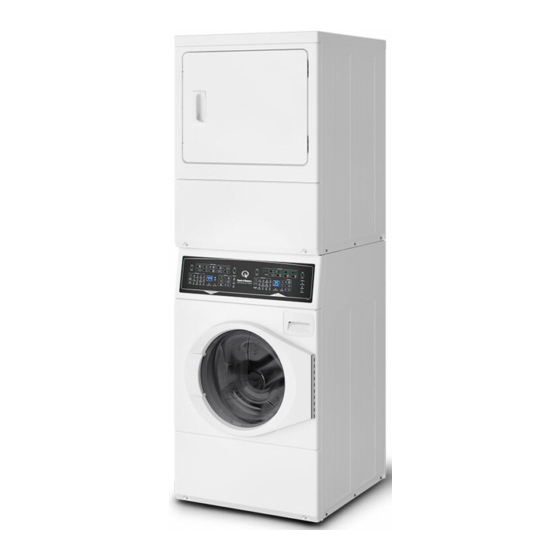
- Page 1 Installation Instructions for Stacked Washer/Dryers Original Instructions Keep These Instructions for Future Reference. CAUTION: Read the instructions before using the machine. (If this machine changes ownership, this manual must accompany machine.) Part No. 807638EN www.speedqueen.com June 2019...
- Page 3 Installation and service must be performed by a appliance. qualified installer, service agency or the gas sup- plier. W053 W052 This product uses FreeRTOS V7.2.0 (www.freertos.org). © Copyright, Alliance Laundry Systems LLC - Part No. 807638EN DO NOT COPY or TRANSMIT...
- Page 4 A “T-Handle” type gas shut-off valve must be installed in the gas supply line to this appliance. • This appliance must not be installed in a bedroom or bath- room. © Copyright, Alliance Laundry Systems LLC - Part No. 807638EN DO NOT COPY or TRANSMIT...
-
Page 5: Table Of Contents
Installer Checklist.................30 © Copyright 2019, Alliance Laundry Systems LLC All rights reserved. No part of the contents of this book may be reproduced or transmitted in any form or by any means without the expressed written consent of the publisher. -
Page 6: Dimensions
* 1986 mm [78.17 in.] 52 mm [2.04 in.] 704 mm [27.73 in.] P (with door closed) 38 mm [1.5 in.] * 333 mm [13.1 in.] Table continues... © Copyright, Alliance Laundry Systems LLC - Part No. 807638EN DO NOT COPY or TRANSMIT... - Page 7 *1140 mm [44.87 in.] *813 mm [32 in.] 683 mm [26.875 in.] *1184 mm [46.62 in.] *1986 mm [78.17 in.] 52 mm [2.04 in.] Table continues... © Copyright, Alliance Laundry Systems LLC - Part No. 807638EN DO NOT COPY or TRANSMIT...
- Page 8 * With leveling legs turned into base. ** For ADA compliance turn legs out from base 0.5 inches. NOTE: Exhaust openings are 102 mm [4 inch] metal ducting. © Copyright, Alliance Laundry Systems LLC - Part No. 807638EN DO NOT COPY or TRANSMIT...
-
Page 9: Installation
5. Slide dryer forward until rear leveling legs slide into notches having a warm, damp climate. in the control cabinet. 6. Lift dryer and place it on a level surface. Reassembling Dryer © Copyright, Alliance Laundry Systems LLC - Part No. 807638EN DO NOT COPY or TRANSMIT... -
Page 10: Order Of Installation Steps
Speed Queen will not cover scheduled repair serv- ices where the installation requirements are not per specifica- tions, nor can products be returned to the authorized dealer in these cases. © Copyright, Alliance Laundry Systems LLC - Part No. 807638EN DO NOT COPY or TRANSMIT... -
Page 11: Connect Fill Hoses
This will release any accumula- ted hydrogen gas. The gas is flammable. Do not smoke or use an open flame during this time. W029 © Copyright, Alliance Laundry Systems LLC - Part No. 807638EN DO NOT COPY or TRANSMIT... -
Page 12: Water Supply Requirements
Make sure the red color-coded hose from the hot water faucet goes to the water mixing valve marked “H” and the blue color-coded hose from © Copyright, Alliance Laundry Systems LLC - Part No. 807638EN DO NOT COPY or TRANSMIT... -
Page 13: Connect Drain Hose To Drain Receptacle
1. Place the drain hose into the standpipe. 2. Remove the beaded tie-down strap from accessories bag and place around standpipe and drain hose. Refer to Figure 8 . © Copyright, Alliance Laundry Systems LLC - Part No. 807638EN DO NOT COPY or TRANSMIT... -
Page 14: Laundry Tub Installation
2. Beaded Strap (tape if necessary) Altitude Orifice Size Figure 10 Part m [feet] mm [inches] 915 [3000] 2.26 [0.0890] D503778 1830 [6000] 2.18 [0.0860] 58719 Table 1 continues... © Copyright, Alliance Laundry Systems LLC - Part No. 807638EN DO NOT COPY or TRANSMIT... - Page 15 For proper operation at altitudes above 915 m [3000 feet] the L.P. gas valve spud orifice size must be reduced to ensure complete combustion. Refer to Table 2 . © Copyright, Alliance Laundry Systems LLC - Part No. 807638EN DO NOT COPY or TRANSMIT...
-
Page 16: Electric Dryer Only - Connect Electrical Plug
© Copyright, Alliance Laundry Systems LLC - Part No. 807638EN DO NOT COPY or TRANSMIT... - Page 17 15. Direct Connection 16. Power Cord Connection Figure 12 1. Disconnect power to dryer. 2. Remove access cover from rear of dryer. D695I_SVG Figure 13 © Copyright, Alliance Laundry Systems LLC - Part No. 807638EN DO NOT COPY or TRANSMIT...
-
Page 18: Connecting Power Cord With Four-Wire Plug
Connecting Power Cord with Four-Wire Plug NOTE: Four-wire cord is required for new branch-cir- cuit installations, mobile homes or where codes do not permit grounding through neutral. © Copyright, Alliance Laundry Systems LLC - Part No. 807638EN DO NOT COPY or TRANSMIT... - Page 19 10. Reinstall access cover and screw. © Copyright, Alliance Laundry Systems LLC - Part No. 807638EN DO NOT COPY or TRANSMIT...
-
Page 20: Connect Dryer Exhaust System
[0.6 inches water column], measured with manometer placed on exhaust duct 610 mm [2 feet] from dry- er (check with dryer running and no load). © Copyright, Alliance Laundry Systems LLC - Part No. 807638EN DO NOT COPY or TRANSMIT... -
Page 21: Exhaust Direction
NOTE: The maximum length of a 102 mm [4 in.] diame- ter flexible metal duct must not exceed 2.4 m [7.87 ft.], as required to meet UL2158, clause 7.3.2.A. © Copyright, Alliance Laundry Systems LLC - Part No. 807638EN DO NOT COPY or TRANSMIT... - Page 22 Dryer Top 152 mm [6 in.] Dryer Rear 102 mm [4 in.] Exhaust Duct 51 mm [2 in.] Clearance to Combustible Ma- terials Table continues... © Copyright, Alliance Laundry Systems LLC - Part No. 807638EN DO NOT COPY or TRANSMIT...
-
Page 23: Reverse Door, If Desired
Figure 26 5. Remove door strike from door liner and reinstall on opposite side. D675I_SVG Figure 23 2. Remove all nine screws. DRY1917N_SVG Figure 27 © Copyright, Alliance Laundry Systems LLC - Part No. 807638EN DO NOT COPY or TRANSMIT... -
Page 24: Wipe Out Inside Of Washer And Dryer Drum
8. Using screwdriver, remove two door plugs, and reinstall on opposite side of door opening. SWD1012N_SVG Figure 32 D317S_SVG Figure 30 9. Reinstall four hinge attaching screws, removed in Step 1. © Copyright, Alliance Laundry Systems LLC - Part No. 807638EN DO NOT COPY or TRANSMIT... -
Page 25: Plug In The Washer And Dryer
3-prong earth/ground plug. Refer to serial plate for specific electrical requirements. NOTE: The wiring diagram is located in the control cab- inet. © Copyright, Alliance Laundry Systems LLC - Part No. 807638EN DO NOT COPY or TRANSMIT... -
Page 26: Washer
110/120 Volts AC (alternating current) 15 Amps. © Copyright, Alliance Laundry Systems LLC - Part No. 807638EN DO NOT COPY or TRANSMIT... - Page 27 The appliance is equipped with a cord having an equipment earth/ ground conductor and a three-prong earth/ground plug. The plug must be plugged into an appropriate outlet that is properly instal- © Copyright, Alliance Laundry Systems LLC - Part No. 807638EN DO NOT COPY or TRANSMIT...
-
Page 28: Check Installation
Level the Washer to readjust leveling legs. Check Heat Source Electric Dryers 1. Close the loading door and start the dryer in a heat setting (re- fer to the operation instructions). © Copyright, Alliance Laundry Systems LLC - Part No. 807638EN DO NOT COPY or TRANSMIT... -
Page 29: Gas Dryers
W158 6. After the dryer has operated for approximately three minutes, exhaust air or exhaust pipe should be warm. © Copyright, Alliance Laundry Systems LLC - Part No. 807638EN DO NOT COPY or TRANSMIT... -
Page 30: Installer Checklist
Start and Run Dryer in Heat Setting to Verify Dryer is nect Electrical Cord Heating. CHECK CHECK D679I_SVG1 Refer to the manual for more detailed information © Copyright, Alliance Laundry Systems LLC - Part No. 807638EN DO NOT COPY or TRANSMIT...
Need help?
Do you have a question about the Speed Queen SF7 and is the answer not in the manual?
Questions and answers