
Related Manuals for Flowserve 3400IQ


Summary of Contents for Flowserve 3400IQ
- Page 1 USER INSTRUCTIONS Installation 3400IQ Digital Positioner Operation Maintenance FCD LGENIM3401-01 – 05/10 Experience In Motion...
-
Page 2: Table Of Contents
Logix 3400IQ Digital Positioner FCD LGENIM3401-01 – 05/10 Contents Terms Concerning Safety General Information Unpacking and Storage Unpacking Storage Pre-installation Inspection Logix 3400IQ Positioner Overview Specifications Positioner Operation Detailed Sequence of Positioner Operations Mounting and Installation Mounting to Valtek Linear Mark One Valves... -
Page 3: How To Order
Pressure Sensor Board User Interface Board Optional Vented Design 10 Parts List 11 Logix 3400IQ Spare Parts Kits (See Figure 22 for item numbers) 12 Logix 3400IQ Mounting Kits 12.1 Valtek Mounting Kits 12.2 Logix O.E.M. Mounting Kits 12.3 NAMUR Accessory Mounting Kit Part Numbers... -
Page 4: Terms Concerning Safety
Logix 3400IQ Digital Positioner FCD LGENIM3401-01 – 05/10 Terms Concerning Safety The safety terms DANGER, WARNING, CAUTION and NOTE are used in these instructions to highlight particular dangers and/or to provide additional information on aspects that may not be readily apparent. -
Page 5: Unpacking And Storage
Logix 3400IQ Digital Positioner FCD LGENIM3401-01 – 05/10 Unpacking and Storage Unpacking While unpacking the Logix 3400IQ positioner, check the packing list against the materials received. Lists describing the system and accessories are included in each shipping container. When lifting the system from the shipping container, position lifting straps to avoid damage to mounted accessories. - Page 6 Logix 3400IQ Digital Positioner FCD LGENIM3401-01 – 05/10 The vent assembly is located in the upper left side of the positioner. The gaps around the assembly as noted by the arrows should be sealed for long term storage. Joints to be sealed...
-
Page 7: Pre-Installation Inspection
Fieldbus compliant digital valve oundation positioner. The positioner is configurable through the local user interface. The Logix 3400IQ utilizes the FF protocol to allow two-way remote communications with the positioner. The Logix 3400IQ positioner can control both double- and single-acting actuators with linear or rotary mountings. The positioner is completely powered by the FF signal. - Page 8 Logix 3400IQ Digital Positioner FCD LGENIM3401-01 – 05/10 Figure 1: Logix 3400IQ Digital Positioner Schematic (air-to-open configuration)
- Page 9 Logix 3400IQ Digital Positioner FCD LGENIM3401-01 – 05/10 Figure 2: System Positioning Algorithm flowserve.com...
-
Page 10: Specifications
Logix 3400IQ Digital Positioner FCD LGENIM3401-01 – 05/10 Specifications Table I: Electrical Specifications Two-wire, 9-32 VDC Power Supply FF compatible Fisco compliant Communications FF Protocol ITK 4.6x Operating Current 23 mA Maximum Voltage 36.0 VDC Table II: Environmental Conditions -40° to 176°F... -
Page 11: Positioner Operation
Once the type of protection has been marked it shall not be changed. Positioner Operation The Logix 3400IQ positioner is an electric feedback instrument. Figure 1 shows a Logix 3400IQ positioner installed on a double-acting linear actuator for air-to-open action. -
Page 12: Detailed Sequence Of Positioner Operations
Control Command. The Logix 3400IQ uses a two-stage, stem-positioning algorithm. The two stages consist of an inner-loop, spool control and an outer-loop, stem position control. Referring again to Figure 1, a stem position sensor provides a measurement of the stem movement. - Page 13 Logix 3400IQ Digital Positioner FCD LGENIM3401-01 – 05/10 is the difference between Control Command and Stem Position : Deviation = 75% - 50% = +25%, where 50 percent is the present stem position. With this positive deviation, the control algorithm sends a signal to move the spool up from its present position.
-
Page 14: Mounting And Installation
Logix 3400IQ Digital Positioner FCD LGENIM3401-01 – 05/10 Mounting and Installation Mounting to Valtek Linear Mark One Valves To mount a Logix 3400IQ positioner to a Valtek linear Mark One valve, refer to Figure 3 and proceed as outlined below. The following tools are required: •... -
Page 15: Mounting To Standard Valtek Rotary Valves (See Figure 4)
Logix 3400IQ Digital Positioner FCD LGENIM3401-01 – 05/10 Mounting to Standard Valtek Rotary Valves (See Figure 4) Figure 4: Standard Rotary Mounting Positioner Bolts ¼-20 (4)* Bracket Bolts -18 (2, not shown) Take-off Arm, Rotary Lock Washer (2) Logix 3400IQ... - Page 16 Orienting the Take-off Arm for Final Lock Down Tube the Logix 3400IQ positioner to the actuator according to the instructions given in Section 5.5, “Tubing Positioner to Actuator.” With supply pressure off, rotate the follower arm in the same direction the shaft would rotate upon a loss of supply pressure.
-
Page 17: Optional Valtek Rotary Mounting Procedure (See Figure 5)
Logix 3400IQ Digital Positioner FCD LGENIM3401-01 – 05/10 WARNING: Failure to follow this procedure will result in positioner and/or linkage damage. Check air-action and stroke carefully before lockdown of take-off arm to spline lever adapter. Optional Valtek Rotary Mounting Procedure... -
Page 18: Namur Mounting Option
30 to 150 psig. A supply regulator is recommended if the customer will be using the diagnostic features of the Logix 3400IQ but is not required. In applications where the supply pressure is higher than the maximum actuator pressure rating a supply regulator is required to lower the pressure to the actuator’s maximum rating (not to be confused with operating range). -
Page 19: Wiring And Grounding Guidelines (See Figure 6)
Minimum operating voltage is 9 VDC. The FF signal to the Logix 3400IQ digital positioner should be in shielded cable. Shields must be tied to a ground at only one end of the cable to provide a place for environmental electrical noise to be removed from the cable. -
Page 20: Segment Compliance Voltage (See Figure 7)
FF source, wiring resistance, barrier resistance (if present), and the Logix 3400IQ positioner voltage. The Logix 3400IQ digital positioner requires that the system allows for a 9.0 VDC drop across the positioner at minimum segment voltage. The actual voltage at the terminals varies from 9.0 to 32.0 VDC depending on the FF signal and ambient temperature. -
Page 21: Cable Requirements
Logix 3400IQ Digital Positioner FCD LGENIM3401-01 – 05/10 The calculated voltage must be greater than 9 VDC in order to safely support the Logix 3400IQ digital positioner. Example: DCS Compliance Voltage = 19 VDC = 300 Ω barrier = 25 Ω... -
Page 22: Startup
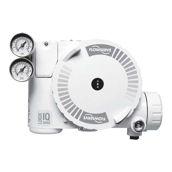
RE-CAL Button Logix 3400IQ Local Interface Operation The Logix 3400IQ local user interface (Figure 8) allows the user to configure the basic operation of the positioner, tune the response, and calibrate the positioner without additional tools or configura- tors. The local interface consists of a RE-CAL button for automatic zero and span setting, along... -
Page 23: Description Of Configuration Dip Switch Settings
Logix 3400IQ Digital Positioner FCD LGENIM3401-01 – 05/10 Description of Configuration DIP Switch Settings The first six DIP switches are for basic configuration. The function of each switch is described below. Air Action This must be set to match the configuration of the valve/actuator mechanical tubing connection and spring location since these determine the air action of the system. - Page 24 Logix 3400IQ Digital Positioner FCD LGENIM3401-01 – 05/10 Figure 9: Default Custom Characterization % Command Table VI : Characteristic Curve Data % Control Command % Command Linear Custom 0.62 8.66 18.8 1.35 16.24 37.6 2.22 23.17 56.4 3.25 30.11 74.0 4.47...
- Page 25 Figure 10: Adjustable GAIN Switch GAIN If the adjustable GAIN selector switch is set to “E” with the auto tune switch on, a Flowserve standard response tuning set will be calculated and used based on response parameters measured during the last RE-CAL.
-
Page 26: Description Of Cal Dip Switch Settings
Logix 3400IQ Digital Positioner FCD LGENIM3401-01 – 05/10 High-Friction Valves Placing the switch to the right optimizes the response for valves and actua- tors with high friction levels. This setting slightly slows the response and will normally stop limit cycling that can occur on high-friction valves. -
Page 27: Manual Jog Calibration Operation
Logix 3400IQ Status Condition The blink codes used to convey the status of the Logix 3400IQ digital positioner are described in the table below. In general, any sequence starting with a green light flashing first is a normal operating mode and indicates that there are no internal problems. - Page 28 Logix 3400IQ Digital Positioner FCD LGENIM3401-01 – 05/10 tion problem. Any sequence starting with a red light flashing indicates that there is an operational problem with the unit. Table VII: Status and Conditions Indication and Resolution G - - - Any sequence starting with a green light flashing first is a normal operating mode and indicates that there are no internal problems.
- Page 29 Logix 3400IQ Digital Positioner FCD LGENIM3401-01 – 05/10 Table VII: Status and Conditions (continued) Indication and Resolution YGRR Local jog control mode The unit has been placed in a local override mode where the valve can only be stroked using the two local jog buttons. It may be cancelled by briefly pushing the RE-CAL button.
-
Page 30: Version Number Checking
Logix 3400IQ Digital Positioner FCD LGENIM3401-01 – 05/10 Table VII: Status and Conditions (continued) Indication and Resolution RGYR Loss of supply pressure The Positioner has determined that the supply pressure is below 15 psi. Check the supply pressure and if OK check the pressure sensor board connections and replace pressure sensor board if necessary. -
Page 31: 375 Handheld Communicator
The LED will change from a red to yellow when the linkage is brought into range. Position 100% Calibration Flag in CALIBRATE_FLAGS During stroke calibration, the Logix 3400IQ digital positioner checks to see if the linkage is placing the stem position sensor in range. If the valve stroke causes stem position measurement to go out of range in the open position, a Position 100% Flag will be generated. -
Page 32: Control And Tuning
Integration Summer: The integral summer within the Logix 3400IQ digital positioner is clamped at +20 percent and -20 percent. If the integration summer is fixed at +20 percent or -20 percent, it usually indicates a control problem. - Page 33 • Locate the DAC_PERCENT • Write this percentage value to IL_OFFSET • Write original value to Integral These tuning sets can be used to obtain initial values for Flowserve products and comparable actuator sizes. The user may need to adjust this tuning to achieve optimal performance for a particular application. Table VIII: Factory Tuning Sets...
- Page 34 Logix 3400IQ Digital Positioner FCD LGENIM3401-01 – 05/10 Figure 11: Logix 3400 Block Diagram...
-
Page 35: Alerts
The travel accumulator is equivalent to a car odometer and sums the total valve movement. Using the user defined stroke length and travel dead-band, the Logix 3400IQ digital positioner keeps a running total of valve movement. When the positioner first powers up, high and low dead-band limits are calculated around the present position. -
Page 36: Cycle Counter
70 percent, no additions are made to the travel accumulator. Now, assume the stem position moves to 80 percent that is outside the present dead-band. The Logix 3400IQ digital positioner calculates the stem movement and adds this number to the travel accumulator. -
Page 37: 7.14.10 Stroke Length
Logix 3400IQ Digital Positioner FCD LGENIM3401-01 – 05/10 7.14.10 Stroke Length Stroke length is used by the travel accumulator. When the stroke length and units are set, the length is used to determine the total travel accumulated. The travel accumulator will have the units associ- ated with stroke. -
Page 38: Characterization Retention
7.15 Characterization Retention Once a custom curve has been loaded into the Logix 3400IQ digital positioner’s memory it is retained in the EPROM until it is either edited or replaced. Turning Custom Characterization Active on or off now selects between a linear response (off), or the new custom curve (on). If either of the other two factory curves is selected it will overwrite the custom curve in RAM only. -
Page 39: Step Signature
15. Return the MODE_BLK to auto. 16. Notify control room the valve is back on-line. The stored signature will remain in the Logix 3400IQ digital positioner RAM until the either the unit is powered down, or another signature is taken which overwrites the previous one. - Page 40 Logix 3400IQ Digital Positioner FCD LGENIM3401-01 – 05/10 EEPROM (Electrically Erasable Programmable Read Only Memory) A device that retains data even when power is lost. Electrically erasable means that data can be changed. EEPROM have a limited number of times data can be rewritten (typically 100,000 to 1,000,000 writes).
-
Page 41: Transducer Block Parameters
Logix 3400IQ Digital Positioner FCD LGENIM3401-01 – 05/10 flowserve.com... - Page 42 Logix 3400IQ Digital Positioner FCD LGENIM3401-01 – 05/10...
- Page 43 Logix 3400IQ Digital Positioner FCD LGENIM3401-01 – 05/10 flowserve.com...
- Page 44 Logix 3400IQ Digital Positioner FCD LGENIM3401-01 – 05/10...
- Page 45 Logix 3400IQ Digital Positioner FCD LGENIM3401-01 – 05/10 flowserve.com...
- Page 46 Logix 3400IQ Digital Positioner FCD LGENIM3401-01 – 05/10...
- Page 47 Logix 3400IQ Digital Positioner FCD LGENIM3401-01 – 05/10 flowserve.com...
- Page 48 Logix 3400IQ Digital Positioner FCD LGENIM3401-01 – 05/10...
- Page 49 Logix 3400IQ Digital Positioner FCD LGENIM3401-01 – 05/10 flowserve.com...
-
Page 50: Maintenance And Repair
Logix 3400IQ Digital Positioner FCD LGENIM3401-01 – 05/10 Maintenance and Repair Driver Module Assembly The driver module assembly moves the spool valve by means of a differential pressure across its diaphragm. Air is routed to the driver module from the regulator through a flexible hose. A barbed fitting connects the flexible hose to the driver module assembly. - Page 51 Logix 3400IQ Digital Positioner FCD LGENIM3401-01 – 05/10 Figure 13: Spool Valve Cover Assembly Make sure the valve is bypassed or in a safe condition. Disconnect the power and air supply to the unit. Remove the driver module cover (Figure 15), using a flat bar or plate in the slot to turn the cover.
- Page 52 Logix 3400IQ Digital Positioner FCD LGENIM3401-01 – 05/10 WARNING: Spool (extending from the driver module assembly) is easily damaged. Use extreme caution when handling spool and spool valve block. Do not handle the spool by the machined portions of spool. The tolerances between the block and spool are extremely tight.
- Page 53 Logix 3400IQ Digital Positioner FCD LGENIM3401-01 – 05/10 Figure 16: Main PCB Assembly Plastic Cover Retaining Screws Plastic Board Cover Main PCB Retaining Screw Main PCB Assembly Regulator Fieldbus PCB Pressure Sensor Board 15. Remove the barbed fitting from the side of the new driver module using the 1/4" nutdriver.
-
Page 54: Regulator
1/4" nutdriver. NOTE: Do not mix the barbed fitting with those from older Logix positioners. Older models contain orifices that will not work in the Logix 3400IQ model. Orifices are brass-colored, barbed fittings are silver-colored. -
Page 55: Checking Or Setting Internal Regulator Pressure
NOTE: Do not mix the regulator with those from older Logix positioners. Older models contain regulators with different settings that will not work in the Logix 3400IQ model. The regulator pressure setting is printed on the top of the regulator. The Logix 3400IQ regulator is set to 17.4 psig. - Page 56 Logix 3400IQ Digital Positioner FCD LGENIM3401-01 – 05/10 WARNING: Observe precautions for handling electrostatically sensitive devices. Figure 17: Driver Module Regulator Pressure Check Make sure the valve is bypassed or in a safe condition. Remove the main cover. Remove the plastic board cover by removing the three retaining screws.
-
Page 57: Spool Valve
Logix 3400IQ Digital Positioner FCD LGENIM3401-01 – 05/10 Install the plastic board cover. Insert the three retaining screws through the plastic cover into the threaded boss and tighten evenly, using a Phillips screwdriver. Do not overtighten (see Figure 16). 10. Reinstall all covers. -
Page 58: Spool Valve Cover
Logix 3400IQ Digital Positioner FCD LGENIM3401-01 – 05/10 10. Slide the spool valve cover assembly over the spool valve until the tang engages into the housing slot. Install the spool valve cover screw and tighten securely (see Figure 13). 11. Reconnect power and air supply to the positioner and perform a stroke calibration. -
Page 59: Stem Position Sensor
NOTE: Do not mix the position sensor with those from older Logix positioners. Older models contain sensors with different ranges that will not work in the Logix 3400IQ model. The wires on the Logix 3400IQ position sensor are red, white and black. -
Page 60: Main Pcb Assembly
Logix 3400IQ Digital Positioner FCD LGENIM3401-01 – 05/10 Figure 19: Stem Position Sensor Orientation Main PCB Assembly The main printed circuit board (PCB) assembly contains the circuit boards and processors that perform control functions of the positioner. The main PCB is to be replaced as a unit. None of the components on the main PCB are serviceable. -
Page 61: Pressure Sensor Board
Pressure Sensor Board On advanced model Logix 3400IQ positioners, a pressure sensor board is installed in the positioner. The pressure sensor board contains two pressure sensors that measure the pressure on output ports 1 and 2. The main PCB electronics automatically senses the presence of the pressure sensor board. - Page 62 Logix 3400IQ Digital Positioner FCD LGENIM3401-01 – 05/10 Disconnect the ribbon cable on the pressure sensor board from the PCB assembly (see Figure 12). Lifting the main board may make this easier. Remove the two screws holding the pressure sensor board to the housing. Lift the metal stiffener plate off the pressure sensor board and set aside for future use.
-
Page 63: User Interface Board
Logix 3400IQ Digital Positioner FCD LGENIM3401-01 – 05/10 Insert two screws through the stiffener plate and pressure sensor board into the threaded holes in the housing and tighten evenly, to 8 in-lb. Connect the ribbon cable on the pressure sensor board to the main PCB assembly. -
Page 64: Optional Vented Design
(from the modulator and regulator) and spool chamber (from the actuator). Back pressure limitations are described below. Two chambers must be vented on the Logix 3400IQ positioners: the main housing chamber and the spool valve chamber (Figures 20 and 21). The main chamber vent is located on the backside of the positioner (see Figure 20). - Page 65 The spool valve chamber (see Figure 21) must also be vented through the spool valve cover. Vented-design Logix 3400IQ positioners are supplied from the factory with a fitting installed in the spool valve cover (item SKU 179477). Connect the necessary tubing/piping to this fitting to route the exhausted natural gas to a safe environment.
- Page 66 Logix 3400IQ Digital Positioner FCD LGENIM3401-01 – 05/10 Figure 22: Exploded Drawing...
-
Page 67: Parts List
Logix 3400IQ Digital Positioner FCD LGENIM3401-01 – 05/10 Parts List Table XI: Parts Item No. Part Item No. Part Threaded Plug Housing Logix 3000IQ Positioner Main Housing Cover Main Vent Cover O-ring, Main Housing Cover Screw, Main Vent Cover Driver Module Cover... -
Page 68: Logix 3400Iq Spare Parts Kits (See Figure 22 For Item Numbers)
Logix 3400IQ Digital Positioner FCD LGENIM3401-01 – 05/10 Logix 3400IQ Spare Parts Kits (See Figure 22 for item numbers.) Table XII: Spare Parts Kits Item Item Description Quantity Description Quantity Kit 2: Driver Module Assembly -40° to 80°C Kit, P/N Kit 5: Feedback Shaft Kit, P/N 199788.999.000... - Page 69 Logix 3400IQ Digital Positioner FCD LGENIM3401-01 – 05/10 Item Item Description Quantity Description Quantity Kit 7: Soft Goods Kit, P/N 199789.999.000 Kit 9: Advanced Model Pressure Sensor Board Kit, P/N 199791.999.000 O-ring, Main Housing Cover Screw, Pressure Sensor Board O-ring, Pressure Sensor to...
-
Page 70: Valtek Mounting Kits
Logix 3400IQ Digital Positioner FCD LGENIM3401-01 – 05/10... -
Page 71: Logix 3400Iq Mounting Kits
Logix 3400IQ Digital Positioner FCD LGENIM3401-01 – 05/10 12.2 Logix O.E.M. Mounting Kits Table XV: Logix O.E.M. Mounting Kits Brand Model Size Mounting Kit 213905 0.5" – 1.5" stroke 141410 171516 0.5" – 1.5" stroke 657 & 667 171517 2" stroke 171516 0.5"... - Page 72 Logix 3400IQ Digital Positioner FCD LGENIM3401-01 – 05/10 Table XV: Logix O.E.M. Mounting Kits (continued) Brand Model Size Mounting Kit 171721 171720 173382 173896 173235 173234 186070 173382* 173896 173325 71 Domotor 173335 173336 171722 173827 173361 173361 “D” 175141...
-
Page 73: Namur Accessory Mounting Kit Part Numbers
Logix 3400IQ Digital Positioner FCD LGENIM3401-01 – 05/10 Table XV: Logix O.E.M. Mounting Kits (continued) Brand Model Size Mounting Kit Vangard 37/64 175128 Air-Torque AT Series AT0 – AT6 SNA Series SNA3 – SNA2000 Automax N Series N250.300 R Series R2 –... -
Page 74: Frequently Asked Questions
As the command increases, the positioner will remain saturated until the command reaches 6 percent (there is a 1 percent hysteresis value added by the positioner). At this point, the stem position will follow the command signal. While in Final Value Cutoff, the Logix 3400IQ LEDs will blink GGGY. -
Page 75: How To Order
Logix 3400IQ Digital Positioner FCD LGENIM3401-01 – 05/10 How to Order Table XVII: How to Order Selection Code Example Protocol Fieldbus* oundation Electronic Standard Diagnostics* Hardware Advanced Diagnostics Options Aluminum, White Paint (Valtek)* Stainless Steel, No Paint (Valtek) Aluminum, Black Paint (Automax) Housing &... -
Page 76: Troubleshooting
Logix 3400IQ Digital Positioner FCD LGENIM3401-01 – 05/10 Troubleshooting Table XVIII: Troubleshooting Failure Probable Cause Corrective Action Verify that voltage source can supply at Voltage of supply source is not high enough least 9 V No LED is Verify current draw of device (23 mA) and... - Page 77 Logix 3400IQ Digital Positioner FCD LGENIM3401-01 – 05/10 Failure Probable Cause Corrective Action Check DIP switch settings and calibrate valve Stroke not calibrated stroke Inner-loop hall sensor not connected Verify hardware connections Position is Check ATO (Air-to-open) and ATC driven fully Wrong air action entered in software (Air-to-close) settings.
- Page 78 Logix 3400IQ Digital Positioner FCD LGENIM3401-01 – 05/10...
- Page 79 Logix 3400IQ Digital Positioner FCD LGENIM3401-01 – 05/10 flowserve.com...
- Page 80 Flowserve products. The purchaser/user should read and understand the Installation Operation Maintenance (IOM) instructions included with the product, and train its employees and contractors in the safe use of Flowserve products in connection with the specific application.
Need help?
Do you have a question about the 3400IQ and is the answer not in the manual?
Questions and answers