Sign In
Upload
Manuals
Brands
Flowserve Manuals
Valve Positioners
3400IQ
Flowserve 3400IQ Manuals
Manuals and User Guides for Flowserve 3400IQ. We have
2
Flowserve 3400IQ manuals available for free PDF download: User Instructions
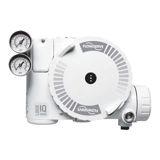
Flowserve 3400IQ User Instructions (148 pages)
Digital Positioner
Brand:
Flowserve
| Category:
Valve Positioners
| Size: 4 MB
Table of Contents
Introduction
2
Table of Contents
2
Copyright, Notices and Trademarks
5
About this Publication
5
About this Manual
5
Symbol Definitions
6
Abbreviations
6
Definitions
7
Technical Assistance
9
References
9
Fieldbus Device Version Checking
10
Software Compatibility
11
Section 1: Logix 3400IQ Digital Positioner Description
13
Introduction
13
Fieldbus Logix 3400IQ Digital Positioner
13
Figure 1.1 Fieldbus Positioner (Logix 3400IQ Digital Positioner)
14
Figure 1.2 Functional Block Diagram of Logix 3400IQ Digital Positioner
14
Figure 1.3 Logix 3400IQ Digital Positioner Block Diagram
14
Fieldbus Overview
16
Figure 1.4 Fieldbus Connecting Control Room and Field Devices
16
Figure 1.5 Fieldbus Devices Contain Device Applications and Function Blocks
17
Section 2: Installation Overview
19
Introduction
19
Installation Components
19
Table 2.1 Components Required for Logix 3400IQ Digital Positioner Installation
19
Installation / Operation Tasks
20
Figure 2.1 Fieldbus Network Components
20
Table 2.2 Installation / Operation Task Summary
20
Section 3: Bench Configuration (Optional)
21
Introduction
21
Bench Check
21
Figure 3.1 Connecting Wiring Device
21
Section 4: Pre-Installation Considerations
23
Introduction
23
Considerations for Logix 3400IQ Digital Positioner
23
Table 4.2 Logix 3400IQ Digital Positioner Power Requirements
24
Table 4.1 Operating Temperature Limits
24
Figure 4.1 Typical Mounting Area Considerations Prior to Installation
24
Section 5: Logix 3400IQ Digital Positioner Installation
25
Introduction
25
Mounting Variations
25
Figure 5.1 Typical Linear Actuator-Mounted Installation
25
Figure 5.2 Rotary Transfer Case Mounting
26
Figure 5.3 Rotary Valve with Four-Bar Linkage
26
Figure 5.4 Logix 3400IQ Digital Positioner Mounted to a Diaphragm Actuator
26
Table 5.1 Foundation Fieldbus Profile Types
27
Wiring Logix 3400IQ Digital Positioner
27
Figure 5.5 Logix 3400IQ Digital Positioner Terminal Block
27
Table 5.2 Logix 3400IQ Digital Positioner Wiring Terminals
28
Intrinsically Safe Applications
28
Figure 5.6 Logix 3400IQ Digital Positioner Terminal Block
28
Powering up the Logix 3400IQ Digital Positioner
30
Section 6: Logix 3400IQ Digital Positioner Configuration
31
Introduction
31
Logix 3400IQ Digital Positioner Communications
31
Device Configuration
32
Logix 3400IQ Digital Positioner Configuration Process
32
Setting Write-Protect Feature
34
Figure 6.1 Write-Protect Dip Switch Location on Main PCB Cover
35
Table 6.1 Write Protect Dip Switch Settings
35
Table 6.2 Write-Protect Feature Truth Table
35
Simulation Dip Switch
36
Establishing Communications
36
Making Initial Checks
36
Table 6.3 Starting Communications with Logix 3400IQ Digital Positioner
36
Table 6.5 Logix 3400IQ Digital Positioner Configuration Task List
37
Configuration Tasks
37
Table 6.4 Logix 3400IQ Digital Positioner Identification
37
Section 7: Operation
39
Introduction
39
Operation Tasks
39
Section 8: Configuration Description
41
Introduction
41
Function Block Application Process
41
Table 8.1 Function Block Application Process Elements
42
Figure 8.1 FBAP Block Diagram Example
42
Block Description
42
Table 8.2 Block Parameter List Column Description
43
Resource Block
44
Table 8.3 Resource Block Parameters
45
Table 8.4 Resource Block Parameter Descriptions
45
Transducer Block
46
Table 8.5 Transducer Block Parameters
46
Figure 8.2 Transducer Block Diagram
49
Table 8.6 Transducer Block Parameter Descriptions
49
Parameter Definitions
50
Analog Output Function Block
53
Table 8.7 AO Function Block Parameter List
54
Figure 8.3 AO Function Block Diagram
55
PID Function Block
57
Table 8.8 PID Control Function Block Parameters
57
Table 8.9 Honeywell PID Parameters
59
Figure 8.4 PID Control Block
60
Table 8.11 Table Description for Block Parameter Summary
62
Table 8.10 PID Tuning Parameter Values
62
Block Parameter Summary
62
Table 8.12 Resource Block Parameter Summary
64
Table 8.13 Transducer Block Parameter Summary
65
Table 8.14 Analog Output Function Block Parameter Summary
69
Table 8.15 PID Function Block Parameter Summary
69
Link Objects
69
Table 8.16 Link Objects Defined for Logix 3400IQ Digital Positioner
70
Table 8.17 Resource Block View List
71
View Objects
71
Table 8.18 Transducer View Block List
72
Table 8.19 AO Block View Table
78
Table 8.20 PID Block View Table
78
Alert Objects
80
Alarm and Event Reporting
80
Trend Objects
83
Domain Objects
84
Device Description
84
Object Dictionary
84
Table 8.21 Block Parameter Index Table
85
Management Virtual Field Device
87
System Management
87
Table 8.22 Logix 3400IQ Digital Positioner SMIB Object Dictionary
87
Table 8.23 System Management Supported Features
88
Table 8.24 SM Agent Objects
88
Table 8.25 SM Sync and Scheduling Objects
89
Table 8.26 SM Address Assignment Objects
89
Network Management
90
Table 8.27 Function Block Scheduling Objects
90
Table 8.28 Logix 3400IQ Digital Positioner NMIB Object Dictionary
91
Table 9.1 Transducer Block Calibration Parameters
98
Two-Point Calibration
98
Troubleshooting
101
Table 10.1 Device Troubleshooting a
102
Incorrect or Non-Compatible Tools
103
Table 10.2 Device Troubleshooting B
103
Non-Functioning Blocks
103
Table 10.3 Device Troubleshooting C
104
Device Diagnostics
105
Table 10.4 Areas of Device Memory Where Data Is Stored
105
Table 10.5 BLOCK_ERR Parameter Bit Mapping
106
Table 10.7 Summary of Configuration Errors
107
Table 10.6 ERROR_DETAIL Parameter Enumeration
107
Table 10.8 AO Block Parameters
109
Table 10.9 PID Function Block Parameters
110
Additional Troubleshooting
110
Figure 10.1 Simulation Dip Switch Location on Main PCB Cover
111
Table 10.10 Setting The Simulation Dip Switch
111
Table 10.11 Simulation Mode Truth Table
111
Table 10.12 Symptom Chart
112
Figure 10.2 Gain Effect Diagram
114
Table 10.13 Logix 3400Iq Digital Positioner Factory Tuning Sets
115
Table 10.14 Logix 3400Iq Digital Positioner Characteristic Curves
117
Figure 10.3 Logix 3400Iq Digital Positioner Characteristic Curves
119
Table 10.15 Transducer Block Characterization Parameters
119
Initiating a Valve Signature
120
Table 10.16 Transducer Block Signature Parameters
122
Software Maintenance
125
Code Download
125
Appendix A: Sample Configuration Record
127
Table 11.1 Logix 3400IQ-011 : RS-011 (RB)
127
Table 11.2 Logix 3400IQ-011 : XD-011 (FVPTB)
129
Table 11.3 Logix 3400IQ-011 : AO-011 (AO)
134
Table 11.4 Logix 3400IQ-011 : PID-011 (PID)
137
List of Figures
142
Advertisement
Flowserve 3400IQ User Instructions (80 pages)
Digital Positioner
Brand:
Flowserve
| Category:
Valve Positioners
| Size: 3 MB
Table of Contents
Table of Contents
2
How to Order
3
Terms Concerning Safety
4
General Information
4
Unpacking and Storage
5
Unpacking
5
Storage
5
Pre-Installation Inspection
7
Logix 3400IQ Positioner Overview
7
Specifications
10
Positioner Operation
11
Detailed Sequence of Positioner Operations
12
Mounting and Installation
14
Mounting to Valtek Linear Mark One Valves
14
Mounting to Standard Valtek Rotary Valves (See Figure 4)
15
Optional Valtek Rotary Mounting Procedure (See Figure 5)
17
NAMUR Mounting Option
18
Tubing Positioner to Actuator
18
Wiring and Grounding Guidelines (See Figure 6)
19
FF Command Input Wiring
19
Grounding Screw
19
Segment Compliance Voltage (See Figure 7)
20
Cable Requirements
21
Intrinsically Safe Barriers
21
DD Support
21
Startup
22
Logix 3400IQ Local Interface Operation
22
Initial DIP Switch Settings
22
Description of Configuration DIP Switch Settings
23
Description of Cal DIP Switch Settings
26
RE-CAL Operation
26
Manual Jog Calibration Operation
27
Local Control of Valve Position
27
Factory Reset
27
Logix 3400IQ Status Condition
27
Version Number Checking
30
375 Handheld Communicator
31
Device Description (DD) Files
31
Calibration
31
Calibrate_Flags
31
Control and Tuning
32
Alerts
35
Final_Value_Cutoff
35
Effects of FINAL_VALUE_CUTOFF on Operation
35
Soft Limits
35
Travel Accumulator
35
Cycle Counter
36
Position Deviation
36
Advanced Features
36
Standard Vs. Advanced Diagnostics
36
Temperature and Pressure Units
36
7.14.10 Stroke Length
37
Characterization Retention
38
Initiating a Valve Signature
38
System Preparation
38
Signature Procedure
38
Step Signature
39
Collection of Stored Signature
39
Glossary
39
Transducer Block Parameters
41
Maintenance and Repair
50
Driver Module Assembly
50
Regulator
54
Checking or Setting Internal Regulator Pressure
55
Spool Valve
57
Spool Valve Cover
58
Stem Position Sensor
59
Main PCB Assembly
60
Pressure Sensor Board
61
User Interface Board
63
Optional Vented Design
64
Parts List
67
Logix 3400IQ Spare Parts Kits (See Figure 22 for Item Numbers)
68
Valtek Mounting Kits
70
Logix 3400IQ Mounting Kits
71
Logix O.E.M. Mounting Kits
71
NAMUR Accessory Mounting Kit Part Numbers
73
Frequently Asked Questions
74
How to Order
75
Troubleshooting
76
Advertisement
Related Products
Flowserve Logix 3400MD
Flowserve Logix 3200MD Plus
Flowserve Logix 3200MD
Flowserve Logix 3200IQ
Flowserve Logix 3000MD Series
Flowserve ColdFlow 341000
Flowserve 3M183
Flowserve Edward 3902Y
Flowserve Logix 3800zb
Flowserve WORTHINGTON 300LNN575
Flowserve Categories
Control Unit
Controller
Water Pump
Valve Positioners
Industrial Equipment
More Flowserve Manuals
Login
Sign In
OR
Sign in with Facebook
Sign in with Google
Upload manual
Upload from disk
Upload from URL