Advertisement
Quick Links
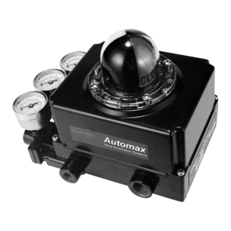
XL90 Series
High-Performance
Positioner
GENERAL INFORMATION
This bulletin is designed to assist in installing, calibrating,
troubleshooting and performing maintenance as re-
quired for the XL90 Series high-performance positioner.
Product users and maintenance personnel should thor-
oughly read and strictly follow the instructions con-
tained in this bulletin prior to operating the positioner.
Any questions concerning this product should be di-
rected to a Flowserve representative.
To avoid possible injury to personnel or dam-
age to valve parts, WARNING and CAUTION
notes must be strictly followed. Modifying this
product, substituting non-factory parts or us-
ing maintenance procedures other than out-
lined could drastically affect performance and
be hazardous to personnel and equipment.
The XL90 high-performance positioner is a two-stage
device and is designed for use in control loops where
fast response is required. The XL90 positioner is de-
signed to be modular and use the P/P module for 3-15
psi input signal or the NT 3000 Series Transducer
Module for 4-20 mA input signal.
The XL90 high-performance positioner is designed as a
four-way device, but can easily be converted to a three-
way device by plugging one of the output ports.
NOTE: The XL90 high-performance positioner must
use the I/P NT 3000 Transducer. The I/P 2000 Trans-
ducer is not acceptable for use with the XL90 Series
Positioner.
Valtek Part No. ??????
The XL90 positioner can handle supply pressures up to
150 psi; thus, a supply regulator is usually not required.
However, a five micron air filter is required for pneu-
matic positioners and a coalescing filter is required for
I/P positioners.
NOTE: The air supply should conform to ISA
Standard S7.3 (a dew point at least 18
below ambient temperature, particle size below 5
microns, oil content not to exceed one part per
million).
The XL90 Series positioner features an adjustable gain
of 400-1100:1. The medium gain setting is standard for
smaller actuators, while the high gain setting is used on
larger actuators (refer to 'Gain Adjustment Procedure'
section for further details.)
POSITIONER OPERATION
The positioner schematic (Figure 1) shows an XL90
Series positioner connected for double-acting service
on a rotary rack-and-pinion actuator. Tension on the
feedback spring provides feedback to the positioner,
which varies as the stem position changes. The spring-
loading force is applied through the feedback linkage
and cam to the positioner's input capsule.
Instrument signal pressure is applied between the
diaphragms in the input capsule. Therefore, the input
capsule serves as a force-balance member, matching
the valve stem position (as measured by tension on the
feedback spring) to the instrument signal.
°
°
F / -8
C
48-1
Advertisement

Subscribe to Our Youtube Channel
Related Manuals for Flowserve XL90 Series


Summary of Contents for Flowserve XL90 Series
- Page 1 Therefore, the input use the I/P NT 3000 Transducer. The I/P 2000 Trans- capsule serves as a force-balance member, matching ducer is not acceptable for use with the XL90 Series the valve stem position (as measured by tension on the Positioner.
- Page 2 Figure 3: Positioner mounting ing air to, nor exhausting air from, their respective sides of the piston. 48-2 Flowserve Corporation, Valtek Control Products, Tel. USA 801 489 8611...
- Page 3 Stroke actuator/valve again to verify there is no misalignment throughout the stroke. 5. Calibrate valve and adjust cam if necessary. (See Figure 4: Alignment “Cam Installation” and “Positioner Calibration” in- structions. 48-3 Flowserve Corporation, Valtek Control Products, Tel. USA 801 489 8611...
-
Page 4: Cam Installation
Use a flat screwdriver to prevent cam rotation and 1. For 3-15 or 3-9 psi range, loosen by hand the zero shaft flats to prevent shaft rotation (if necessary). adjustment locking knob and adjust zero adjust- 48-4 Flowserve Corporation, Valtek Control Products, Tel. USA 801 489 8611... - Page 5 The average actuator pressure level of output 1 and 2 is approxi- 8. Replace rubber cap over balance adjustment screw. 48-5 Flowserve Corporation, Valtek Control Products, Tel. USA 801 489 8611...
-
Page 6: Gain Adjustment Procedure
5. When the gain is set to the desired position, firmly Mounting Screws Termination tighten both lock-down screws. Figure 9: NT 3000 Circuit Board Module 6. Turn on supply pressure. Check actuator respon- (housing cover removed) 48-6 Flowserve Corporation, Valtek Control Products, Tel. USA 801 489 8611... -
Page 7: Positioner Maintenance
1. Remove the feedback spring (47) and rotate the span and zero arms (40, 46) out of the way. feature is enabled and adjusted. 48-7 Flowserve Corporation, Valtek Control Products, Tel. USA 801 489 8611... - Page 8 13. Lubricate and replace O-ring (37) on movable seat ring (34). Carefully reinstall seat ring into upper relay body (9), being careful not to damage seating surface or O-rings. 14. Reinstall poppets (28), poppet springs (29), Seat 48-8 Flowserve Corporation, Valtek Control Products, Tel. USA 801 489 8611...
- Page 9 2. Balance pressure not set correctly 2. Adjust balance pressure according to page 5. 3. Gain is set too high 3. Lower gain mechanism until overshoot is minimized 48-9 Flowserve Corporation, Valtek Control Products, Tel. USA 801 489 8611...
- Page 10 128 Jam nut All of the above parts are in stock and can be purchased in a spare parts kit. For selecting and ordering the appropriate kit or a new positioner, contact your Flowserve representative or the factory. 48-10 Flowserve Corporation, Valtek Control Products, Tel. USA 801 489 8611...
- Page 11 All of the above parts are in stock and can be purchased in a spare parts kit. For selecting and ordering the appropriate kit or a new positioner, contact your Flowserve representative or the factory. *Consult factory for parts. 48-11...
- Page 12 . y l i l l c t i t t i v i t c t i t i s t i s “ ” t i s 48-12 Flowserve Corporation, Valtek Control Products, Tel. USA 801 489 8611...
- Page 13 — , t i — — e t i c i t , t i — , t i — — c i t 48-13 Flowserve Corporation, Valtek Control Products, Tel. USA 801 489 8611...
- Page 14 Consult your local Flowserve representative for ordering information. , t i — t t i , t i — , t i — 48-14 Flowserve Corporation, Valtek Control Products, Tel. USA 801 489 8611...
- Page 15 , t i , t i — — , s t , t i , t i — — , t i , t i — — , s t 48-15 Flowserve Corporation, Valtek Control Products, Tel. USA 801 489 8611...
- Page 16 Flowserve Corporation has established industry leadership in the design and manufacture of its products. When properly selected, this Flowserve product is designed to perform its intended function safely during its useful life. However, the purchaser or user of Flowserve products should be aware that Flowserve products might be used in numerous applications under a wide variety of industrial service conditions.
Need help?
Do you have a question about the XL90 Series and is the answer not in the manual?
Questions and answers