Table of Contents
Advertisement
Quick Links
Advertisement
Table of Contents

Related Manuals for Sonel PQM-750


Summary of Contents for Sonel PQM-750
- Page 3 USER MANUAL POWER QUALITY ANALYZER PQM-750 SONEL S.A. Wokulskiego 11 58-100 Świdnica Poland Version 1.00 15.10.2024...
- Page 4 Due to continuous product development, the manufacturer reserves the right to make changes to functionality, features and technical parameters of the analyzers. The man- ufacturer provides long-term support for the product, adding new functionalities and fix- ing noticed errors. • This manual describes the firmware version 1.00. PQM-750 – USER MANUAL...
-
Page 5: Table Of Contents
2.22 Firmware update ....................37 2.23 Downloading of system logs ................... 37 2.24 RTC coin cell battery ....................37 2.25 Emergency reset ....................38 3 Cybersecurity ....................39 3.1 Recommendations ....................39 3.2 Password management..................39 PQM-750 – USER MANUAL... - Page 6 6.5.21 Mains signalling ......................67 6.5.22 Transients ........................67 6.5.23 Emissions in 2 kHz do 9 kHz band .................. 68 6.5.24 Emissions in 8 kHz do 150 kHz band ................68 6.6 Event detection ...................... 68 PQM-750 – USER MANUAL...
- Page 7 6.23 Standards ....................... 76 6.23.1 Compliance with standards ..................... 77 6.23.2 Product specification according to IEC 62586 ..............79 7 Cleaning and maintenance ................80 8 Storage ......................80 9 Dismantling and utilization ................80 10 Manufacturer ....................80 PQM-750 – USER MANUAL...
-
Page 8: General Information
• CAT III – concerns measure- ments performed in buildings in- stallations, • CAT IV – concerns measure- ments performed at the source of low voltage installation. PQM-750 – USER MANUAL... -
Page 9: Safety
The analyzer is equipped with an internal Li-Ion battery, which has been tested by an independent laboratory and is quality-certified for compliance with the standard UN Manual of Tests and Criteria Part III Subsection 38.3 (ST/SG/AC.10/11/Rev.5). Therefore, the analyzer is approved for air, maritime and road transport. PQM-750 – USER MANUAL... -
Page 10: General Characteristics
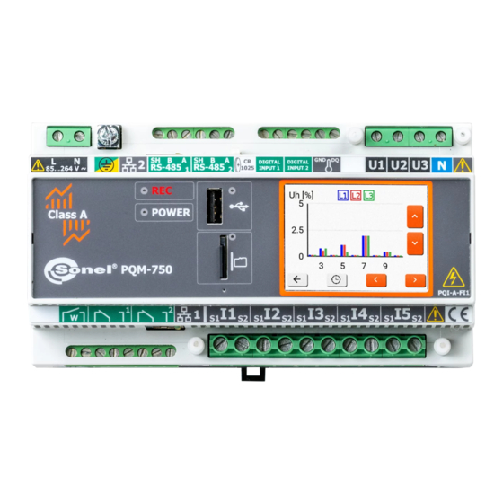
General characteristics Fixed mounted Power Quality Analyzer PQM-750 (Fig. 1) is an advanced device providing its users with a comprehensive features for measuring, analyzing and recording parameters of 50/60 Hz power networks and power quality in accordance with the European Standard EN 50160. Analyzer is fully compliant with the requirements of IEC 61000-4-30:2015, Class A and IEC 62586 (PQI-A-FI1 classifi- cation). - Page 11 The third row in the tables shows the strip number assigned to given terminal. See also Table 1. PQM- 750 terminal block connectors. Watchdog relay, digital outputs Current inputs Fig. 2. PQM-750 Power Quality Analyzer. Bottom side view The RJ-45 LAN1 input is also visible. PQM-750 – USER MANUAL...
-
Page 12: Mounting Of The Analyzer
A B SH A B SH 24 25 26 27 28 29 30 31 32 33 34 Fig. 3. PQM-750 Power Quality Analyzer. Top side view. The RJ-45 LAN2 input and the RTC clock backup battery socket are also visible. Mounting of the analyzer 1.3.1 Mounting on the DIN rail... -
Page 13: Mounting On The Wall
This is shown in Fig. 6. After installing the strips, a sealing wire should be fed through the holes in the posts on both sides of the strips. Fig. 6. Sealing of the measurement terminals. PQM-750 – USER MANUAL... -
Page 14: Terminal Block Connections
Terminal block connections Table 1 list all the terminal block connectors used on PQM-750 analyzer. Table 1. PQM-750 terminal block connectors. Connector strip Cable cross section in Stripped length Connector name Designation number in mm Watchdog relay NO contact 0.5 – 3.3... -
Page 15: Power Supply Of The Analyzer
Selected parameters are aggregated (averaged) according to the time selected by the user and may be stored on a memory card. In addition to average value, it is also possible to record minimum and maximum values during the averaging period. PQM-750 – USER MANUAL... - Page 16 Some of the unique features of this device make it distin- guishable from other similar analyzers available in the market. Table 2 presents a summary of parameters measured by analyzer, depending on the mains type. PQM-750 – USER MANUAL...
- Page 17 ✓ ✓ ✓ ✓ ✓ ✓ ✓ ✓ ✓ ✓ ✓ ✓ ✓ ✓ ✓ ✓ ✓ ✓ ✓ harmonics active power h256 ✓ ✓ ✓ ✓ ✓ ✓ ✓ ✓ ✓ harmonics reactive power h256 PQM-750 – USER MANUAL...
- Page 18 In 3-phase 3-wire networks the total reactive power is calculated as inactive power �� = √�� − �� (see discussion on reactive power in �� Power Quality Guide document). Voltage transients are measured when optional transient module is installed (option “TR”). PQM-750 – USER MANUAL...
-
Page 19: Operation Of The Analyzer
(see also sec. 2.8.3). You can also then enable GUI protection against unauthorized use and set PIN codes (sec. 2.3). After switching on, the analyzer is activated with the last measurement configuration. PQM-750 – USER MANUAL... -
Page 20: Restricting Access To Gui
Entering the Administrator PIN code gives access to all GUI options. The method of regaining ac- cess to the meter GUI in the event of forgetting the Administrator PIN code is given in sec. 3.2. PQM-750 – USER MANUAL... -
Page 21: Verifying The Connection
– the accuracy of angles cannot be verified, because the RMS voltage value is too low (less than 1% of U • – incorrect angles of vectors. In three-phase systems, this icon is displayed, among others, in case of reversed sequence of voltage phases. PQM-750 – USER MANUAL... -
Page 22: Communication And Data Transmission
The analyzer supports single IP address on both physical connectors. The second LAN port can be used to simplify network connections when other device needs ethernet con- nection, or can be used to connect an external panel display that interfaces with the PQM-750 web- server. -
Page 23: Viewing Real Time Measurement Data
The right and left orange arrows allows switching between all the real time data screen in a circular manner. Example screens are shown on Fig. 12, Fig. 13, Fig. 14 and Fig. 15. Fig. 12. “U, THDU, f” screen. The upper frequency is 10/12-cycle frequency, and the bottom is 10-second frequency. PQM-750 – USER MANUAL... -
Page 24: Taking Measurements
Fig. 15. 2-150 kHz screen. Taking measurements 2.8.1 Start / stop of recording In the PQM-750 analyzer, recording starts automatically after starting the meter if no errors preventing recording are detected (e.g. missing memory card). When recording is active, the red LED lights up continuously. -
Page 25: Recording Configuration
Fig. 17 2. System type. On this screen you may select the mains type. Fig. 18 3. Frequency selection. Select nominal frequency of the system: 50 / 60 Hz. PQM-750 – USER MANUAL... - Page 26 6. The last screen of the configuration wizard is the summary. If all the configuration parameters are correct, confirm the settings by pressing accept button. Fig. 22 7. The next screen confirms that the configuration has been suc- cessfully changed and that recording has been started. PQM-750 – USER MANUAL...
-
Page 27: Network Interface (Webserver)
• password: pqm Detailed instructions for using the www service are described in a separate document. Fig. 23. PQM-750 webserver logon screen. 2.10 Measuring circuits The analyzer may be connected directly to the following types of networks: 1-phase (Fig. 24) 2-phase (split-phase) with split-winding of the transformer (Fig. - Page 28 This channel can be used, for example, to measure leakage current. The following figures show schematically how to connect the analyzer to the tested network depend- ing on its type. Fig. 24. Wiring diagram – single phase, direct voltage connection. PQM-750 – USER MANUAL...
- Page 29 Fig. 25. Wiring diagram – split-phase, direct voltage connection. Fig. 26. Wiring diagram – 3-phase 4-wire system, direct voltage connection. PQM-750 – USER MANUAL...
- Page 30 Fig. 27. Wiring diagram – 3-phase 3-wire, direct voltage connection. Fig. 28. Wiring diagram – 3-phase 3-wire with current measurement using Aron method. PQM-750 – USER MANUAL...
-
Page 31: Data Recording
Regardless of the selected recording mode, the analyzer can store data from a maximum of 200 days, if this number is exceeded, data from the oldest days is deleted. Waveforms, RMS , transient and other graphs are saved in the user data area, even if the related events come from normative data. PQM-750 – USER MANUAL... -
Page 32: Normative Recording
Apparent energy Tangent φ (4-quadrant) ✓ ✓ Flicker Plt In addition to the parameters listed in Table 3, the analyzer records events defined in the EN 50160 standard: voltage dips, swells, interruptions and RVC (rapid voltage changes). PQM-750 – USER MANUAL... -
Page 33: Configuration Changes And Multi-Access
2.13 Configuration changes and multi-access The PQM-750 analyzer offers several ways to change its own settings. Settings are understood as all of the analyzer's configuration parameters, including: • general analyzer settings (e.g. time zone or GUI language), which are stored in EEPROM, •... -
Page 34: Ftp Client
Electrical Devices) and a common language for their configuration, ensuring interoperability between devices and engineering tools. PQM-750 supports edition 2.1 of this standard. Detailed information about this protocol along with a description of the data model is available in the dedicated user manual. -
Page 35: Time Synchronization
A, the accuracy of measurement must be the same as previously specified (i.e., max. 1 period of mains). There are two options for PQM-750 to fulfil these timing requirements: • GPS synchronization by adding additional external GPS-1 module to the main analyzer module, •... -
Page 36: Data Flagging Concept
In order to ensure the compliance of the whole measurement with requirements of IEC 61000- 4-30 in terms of time marking for devices of Class A, the internal analyzer clock must be synchronized to UTC, and GPS or IRIG-B signal must be available for the whole process of recording. PQM-750 – USER MANUAL... -
Page 37: Configuration Of 1-Wire Temperature Sensors
DQ and GND terminals of the analyzer. Each sensor has an internal unique serial number stored in non-volatile ROM memory, which is used to identify the sensor on the bus. The way of connecting 1-Wire sensors to the PQM-750 analyzer is shown on Fig. 30. Connection of 1-Wire sensors to PQM-750 analyzer. -
Page 38: Digital Inputs
C→O→C (closed contacts, open contacts, closed contacts). In the case of changeover relays (SPDT), such as those used in the PQM-750, the O state (open con- tacts) means the relay is off (contacts in the position as on the sticker on the housing), and the C state (closed contacts) means the relay is on (energized). -
Page 39: Firmware Update
After inserting a new battery into the holder, insert it into the socket in the meter, remembering the correct orientation of the holder. PQM-750 – USER MANUAL... -
Page 40: Emergency Reset
Resetting the meter during normal operation may result in the loss of all or part of the rec- orded data. The file system on memory cards may become corrupted. A short press of the reset button reinitializes the LCD display and will not reset the processor. PQM-750 – USER MANUAL... -
Page 41: Cybersecurity
After this operation, the www service administrator pass- word is reset to ‘pqm’. After logging back into the service, set a new, strong password using the guide- lines from sec. 3.1. PQM-750 – USER MANUAL... -
Page 42: Used Tcp/Udp Ports
DHCP client Dynamic Host Configuration Protocol Communication with DNS server to translate client domain names into IP addresses Communication with system controller via SonelFrame server 4005 SonelFrame protocol by Sonel S.A. Possibility to change port number PQM-750 – USER MANUAL... -
Page 43: Design And Measurement Methods
For PQM-750 analyzer the phase error between voltage and current harmonics of the order of 256 is less than 4°. -
Page 44: Frequency Measurement
4 nearest interharmonic bins (root of the sum of the squares) if the frequency is not in the centre of the bin. The PQM-750 uses both methods, and selects it dynamically and automatically depending on the actual mains frequency and the ripple signal frequency. -
Page 45: Measurement Of Emissions In The 8 Khz To 150 Khz Band
72 frequency bands – from 8 kHz to 150 kHz. In one measurement window of the main path lasting approximately 200 ms, there are tens such 500 microsecond measurements for each of the three meas- ured channels. PQM-750 – USER MANUAL... -
Page 46: Events Detection
Table 6 lists all parameters for which the events can be detected, including specification of threshold types. The “Waveform and RMS ” column indicates those events which has the option to enable recording of waveforms and RMS charts (this list may be expanded in future firmware re- leases). PQM-750 – USER MANUAL... - Page 47 Since the event detection threshold may only be a positive value and to ensure proper detection for these parameters, the analyzer compares absolute values of these parameters with the set threshold. PQM-750 – USER MANUAL...
-
Page 48: Waveshape Variation Events
4.0 the hysteresis is 0.02×4.0 = 0.08). 4.9.1 Waveshape variation events The PQM-750 provides a method for detecting abnormalities in the shape of the voltage waveform: waveshape variation events. This method compares two adjacent periods of the voltage waveform and the difference between them is calculated and their maximum amplitude is checked - these values are then compared with the threshold set by the user. -
Page 49: Phase Jump Events
"systemic" phenomenon and not as a requirement to occur in many phases simultaneously). In the case of recording for compliance with the selected standard, which also includes the RVC measurement, RVC parameters are taken from the default settings of the selected standard. PQM-750 – USER MANUAL... -
Page 50: Methods Of Parameter's Averaging
The arithmetic average (AVG) is calculated according to the formula: �� ������ = ∑, ������ �� ��=1 where: • is subsequent parameter value to be averaged, • N is the number of values to be averaged. PQM-750 – USER MANUAL... -
Page 51: Calculation Formulas
�� = ������ = cos(�� − �� �� �� where is an absolute angle of the fundamental compo- Displacement power factor nent of voltage U is an absolute angle of the fundamental component of current I PQM-750 – USER MANUAL... - Page 52 Interharmonic components acc. to IEC 61000-4-7 of voltage and current x (interharmonic order) = 0..256 (sub-harmonic also includes the 5 Hz bin) PQM-750 – USER MANUAL...
- Page 53 U and I Short-term flicker calculated according to IEC 61000-4-15 �� ∑ �� ��=1 ������ = √ �� Long-term flicker ���� �� where P is subsequent i-th indicator of short-term flicker PQM-750 – USER MANUAL...
- Page 54 = ∑ �� ( ������ ) ��(��) �� �� ��=1 where: i is subsequent number of the 10/12-period measurement Apparent energy window, S(i) represents apparent power S calculated in i-th meas- uring window T(i) represents duration of i-th measuring window (in hours) PQM-750 – USER MANUAL...
-
Page 55: Split-Phase Network
where: is the increase in total reactive energy Qtot(C+) (Budeanu/IEEE-1459) in a given averaging pe- tot(C+) Qtot(C+) riod, is the increase in total active energy taken E Ptot+ Ptot+ a given averaging period PQM-750 – USER MANUAL... - Page 56 10/12-period measure- Total apparent energy Stot ment window (i) represents the total apparent power S calculated in i-th measuring window T(i) represents duration of i-th measuring window (in hours) PQM-750 – USER MANUAL...
-
Page 57: 3-Phase 4-Wire Network
(4-quadrant) tot(L-) tot(C+) Total active energy (im- P+tot calculated as for the split-phase network ported and exported) P-tot Qtot(L+) Total Budeanu reactive Qtot(C-) energy varh calculated as for the split-phase network Qtot(L-) (4-quadrant) Qtot(C+) PQM-750 – USER MANUAL... - Page 58 Operator mag() indicates vector module �� (�� + ���� + �� �� ��1 ��1 ��1 �� = ������(�� Current positive se- quence component where I are vectors of fundamental current components I Operator mag() indicates vector module PQM-750 – USER MANUAL...
-
Page 59: 3-Phase 3-Wire Networks
1 or -1. The sign is determined deanu and IEEE 1459) basing on the angle of phase shift between standardized symmetrical components of voltages and currents Total Budeanu distortion �� Btot �������� power PQM-750 – USER MANUAL... - Page 60 10/12-period measure- Total apparent energy Stot ment window (i) represents the total apparent power S calculated in i-th measuring window T(i) represents duration of i-th measuring window (in hours) PQM-750 – USER MANUAL...
-
Page 61: Technical Data
• (rated input current) – value obtained by dividing nominal current I by the current trans- ducers ratio. For PQM-750 equipped with 5 A current transformers the I equals 5 A. • – maximum continuous input current. For PQM-750 I = 4 x I •... -
Page 62: Current Inputs
Pretrigger time from 10% to 90% of the recording time - amplitude (50 V…5000 V) Detection method - slew rate (dV/dt; from 100 V/500 µs to 100 V/5 µs) Inactivity time after detection (hold-off) PQM-750 – USER MANUAL... -
Page 63: Measured Parameters - Accuracy, Resolution And Ranges
+45C, may vary from reference measurement by ±0.1% Udin (multiplier 1.0) at +55C, may vary from reference measurement by ±0.2% U (multiplier 2.0) Fig. 33. Measurement variation multiplier M as a function of ambient temperature. PQM-750 – USER MANUAL... -
Page 64: Rms Voltage
Harmonic subgroups acc. to IEC 61000-4-7, class I 0.3% THD-F U 0 %...20% 0.01% THD-R U (absolute uncertainty) (harmonics 1…50) ≤ U ≤ 80% U 120% U THD-F U 64 V ≤ U ≤ 690 V THD-R U (harmonics 1…256) PQM-750 – USER MANUAL... -
Page 65: Current Harmonics, Thd I, Tdd, K-Factor, Factor K
5 Hz bin 0.3% TID-F U 0 %...20% 0.01% TID-R U (absolute uncertainty) (interharmonics 0…50) ≤ U ≤ 120% U 80% U 64 V ≤ U ≤ 690 V TID-F U TID-R U (interharmonics 0…256) PQM-750 – USER MANUAL... -
Page 66: Current Interharmonics, Tid I
(64 V ≤ U ≤ 690 V) 0.4 % ≤ I Apparent power S 2% I < 5% I 0.2 % ≤ I ≤ I Apparent energy E 5% I = 5 A = 20 A PQM-750 – USER MANUAL... -
Page 67: Displacement Power Factor (Cosφ/Dpf) And Power Factor
– additional uncertainty of the measurement of the phase between voltage and current har- monics. uncertainty may be calculated when the phase angle is known for the considered frequency band. Table 8 shows the phase error between voltage and current harmonics (without external trans- ducers). PQM-750 – USER MANUAL... - Page 68 Table 8. Phase error of PQM-750 analyzer depending on frequency. 100…3000 Hz Frequency range 50/60 Hz 3001..15360 Hz ≤0.05 ≤1 ≤4 Error Phase error introduced by transducers and probes may be usually found in their technical docu- mentation. In this case, we need to estimate the resultant phase error between the voltage and the current for a given frequency caused by all elements of the measuring circuit: current and voltage trans- ducers, probes, and the analyzer.
-
Page 69: Flicker
5 Hz ≤ f ≤ 30000 control signal 4 s.d. 5% if 3% U ≤ U ≤ 15% U 6.5.22 Transients Parameter Range and conditions Resolution Basic uncertainty (5% + 25 V) ±6000 V Voltage transients 4 s.d. PQM-750 – USER MANUAL... -
Page 70: Emissions In 2 Khz Do 9 Khz Band
Event duration hh:mm:ss.ms Half cycle One cycle Detection threshold Set by the user in percentage of U or absolute values. Event detection (1-cycle RMS refreshed every ½ cy- based on the measurement of U RMS(1/2) cle). PQM-750 – USER MANUAL... -
Page 71: Other Parameters
Comparison of two subsequent periods of 1.0…100% U Waveshape variation (voltage only) voltage waveform. See sec. 4.9.1. Comparison of two or three fundamental 1…359° Phase jumps (voltage only) voltage phase angles calculated from sub- (angle degrees) sequent periods of voltage waveform PQM-750 – USER MANUAL... -
Page 72: Event Detection Hysteresis
✓ ✓ ✓ Voltage total harmonic distortion THD-F U, THD-R U ✓ ✓ ✓ Current total harmonic distortion THD-F I, THD-R I ✓ Total Demand Current (TDD) ✓ ✓ ✓ …U Voltage harmonic amplitudes U h256 PQM-750 – USER MANUAL... -
Page 73: Power Supply
3-phase 4-wire with a neutral conductor (voltage terminals: U1, U2, U3, N, 3-phase 4-wire 3-phase 3-wire (voltage terminals: U1, U2, U3, E) 3-phase 3-wire 3-phase 3-wire (voltage terminals: U1, U2, U3, E) 3-phase 3-wire (Aron) calculated) PQM-750 – USER MANUAL... -
Page 74: Communication Protocols
Default setting: 8 data bits, 1 stop bit, even parity MODBUS TCP/IP TCP port 502 (default), max. 5 clients IEC 61850 TCP port 102 SonelFrame TCP port 4005, proprietary Sonel S.A. protocol for managing the analyzer 6.12 Ethernet Ethernet 2x RJ45 10/100 Base-T acc. to IEEE 802.3 LED green:... -
Page 75: Digital Inputs
6.17 1-wire temperature sensor input 1-wire temperature sensor input Operation mode Isolated parasitic power 1-wire bus Max. number of sen- sors Max. bus length 100 m Compatible sensors DS18B20, DS18B20-PAR Isolation type Digital isolator Isolation rating 1000 V rms PQM-750 – USER MANUAL... -
Page 76: Replaceable Coin Cell
Immunity to electrostatic discharge Air discharge: 8 kV Contact discharge: 6 kV IEC 61000-4-3 sinusoidal modulation 80% AM, 1 kHz Immunity to radio frequency interferences 80…1000 MHz, 10 V/m 1.4…2.0 GHz, 3 V/m 2.0…2.7 GHz, 1 V/m PQM-750 – USER MANUAL... - Page 77 0.5 MHz…30 MHz: 60 dBV avg EN 55032 (CISPR 32) Compliance statement: PQM-750 is a class A product. In a domestic environment this product may cause radio inter- ference in which case the user may be required to take adequate measures (e.g. increasing distance between affected devices).
-
Page 78: Mechanical Tests
Number of stresses: 2 each side 6.23 Standards Conformity Note SONEL S.A. hereby declares that the device type PQM-750 complies with Directives 2014/35/UE and 2014/30/UE. The full text of the EU Declaration of Conformity is available at the following website address: https://sonel.pl/en/download/declaration-of-conformity/... -
Page 79: Compliance With Standards
EN 55032 (CISPR 32):2015 – Electromagnetic compatibility of multimedia equipment - Emission Requirements. • IEC 61000-6-5:2015 – Electromagnetic compatibility (EMC) - Part 6-5: Generic standards - Immunity for equipment used in power station and substation environment. PQM-750 – USER MANUAL... - Page 80 Rapid Voltage Changes Compliant with IEC 61000-4-30 Class A of the measurement method and uncer- (RVC) tainty Compliant with IEC 61000-4-30 Class A of the measurement method and uncer- Magnitude of current tainty PQM-750 – USER MANUAL...
-
Page 81: Product Specification According To Iec 62586
. If trans- = k I ducers are used then I , where k is the transducer ratio, e.g. for a transducer 100 A : 5 A k=20, I =100 A, I =5 A. PQM-750 – USER MANUAL... -
Page 82: Cleaning And Maintenance
The manufacturer of the device and provider of guarantee and post-guarantee services: SONEL S.A. Wokulskiego 11 58-100 Świdnica Poland tel. +48 74 884 10 53 (Customer Service) e-mail: customerservice@sonel.com web page: www.sonel.com NOTE! Service repairs must be performed only by the manufacturer. PQM-750 – USER MANUAL...
Need help?
Do you have a question about the PQM-750 and is the answer not in the manual?
Questions and answers