Table of Contents
Advertisement
Quick Links
Advertisement
Table of Contents

Related Manuals for Sonel PVM-1020


Summary of Contents for Sonel PVM-1020
- Page 3 USER MANUAL PHOTOVOLTAIC METER PVM-1020 SONEL S.A. Wokulskiego 11 58-100 Świdnica Poland Version 1.02 30.03.2022...
- Page 4 PVM-1020 is a modern, state-of-the art measuring instrument, easy to operate and safe. Read this manual to avoid mistakes during the measurements and prevent operational problems. PVM-1020 – USER MANUAL...
-
Page 5: Table Of Contents
2.1 Turning the meter on and off, display backlight ............9 2.2 Selection of general measurement parameters ............9 2.3 Remembering the last measurement result ............. 9 2.4 Connectivity between IRM-1 and PVM-1020 ............11 2.4.1 Pairing the meters ......................11 2.4.2... - Page 6 11.1.9 Converting measurement results to STC conditions ............51 11.2 Other technical specifications ................52 12 Accessories ....................53 12.1 Standard accessories .................... 53 12.2 Optional accessories ....................54 13 Manufacturer ....................55 14 Laboratory services ..................56 PVM-1020 – USER MANUAL...
-
Page 7: General Information
CAT II – concerns measurements performed in circuits directly connected to low voltage in- stallations, CAT III – concerns measurements performed in buildings installations, CAT IV – concerns measurements performed at the source of low voltage installation. PVM-1020 – USER MANUAL... -
Page 8: Safety
It may also expose the user to the risk of electric shock. Do not carry the meter holding it by the wire of current clamps Repairs may be performed only by an authorised service point. PVM-1020 – USER MANUAL... -
Page 9: General Characteristics
CONT General characteristics PVM-1020 is a multifunctional measuring device designed to measure the parameters of photovoltaic systems and the parameters of the inverter connection points to the power grid. It allows you to per- form the necessary measurements for a photovoltaic system according to category 1 specified in standard "IEC 62446-1 - Photovoltaic systems (PV). -
Page 10: Compliance With Standards
Compliance with standards PVM-1020 meets the requirements of the following standards: IEC 61557-1 – Electrical safety in low voltage distribution systems up to 1 000 V AC and 1 500 V DC – Equipment for testing, measuring or monitoring of protective measures – Part 1: General requirements. -
Page 11: Quick Start
When entering the start screen of a given function by pressing the ESC button (or when it is dis- played automatically 10 seconds after the measurement has been taken), the user may recall this re- sult by pressing ENTER. PVM-1020 – USER MANUAL... - Page 12 Sounds: on / off Pairing with IRM-1 meters Software updates: no /yes The update process is triggered by an application on the computer. You can exit it by turning off the meter. Factory reset: no / yes PVM-1020 – USER MANUAL...
-
Page 13: Connectivity Between Irm-1 And Pvm-1020
Connectivity between IRM-1 and PVM-1020 If the IRM-1 meters have been paired with the PVM-1020, the device searches for them when turned on. When IRM-1 is found, a connection is established and the screen shows . The PVM- 1020 remembers the last 3 paired IRM-1's. -
Page 14: Unpairing
2.4.2 Unpairing In the PVM-1020 settings, enter the pairing screen with IRM-1. One paired IRM-1 Multiple paired IRM-1's within range of the meter within range of the meter .Use the serial number of IRM-1 to select the de- vice to be unpaired Use buttons to display "- - - -"... -
Page 15: Automatic Completion Of Results With Environmental Parameters After Regaining Connection With The Irm-1
Automatic completion of results with environmental parameters after regaining connection with the IRM-1 It may happen that in the course of measurements the PVM-1020 moves away from the IRM-1 so far, that communication between them is lost. If the measurements are continued, then after the connec-... -
Page 16: Measurements
▼ ▪ 500 V general parameters setting. ▪ 1000 V Connect test leads according to the drawings. The PV system has an accessible, grounded struc- ture (including frames of the module). Then one measurement is enough. PVM-1020 – USER MANUAL... - Page 17 Press START. Measurement will begin. Read out the result. – test voltage - compliance of the result with the require- ments of IEC 62446 standard E - solar irradiance of the tested object – temperature of the tested object PVM-1020 – USER MANUAL...
- Page 18 (both leads)! Activation of current limit. The symbol displayed is accompanied by a continuous beep. The tested object is live. The measurement is possible, but without guaranteed accuracy. The tested object is being discharged. PVM-1020 – USER MANUAL...
-
Page 19: Measurement Of Insulation Resistance (Ac)
▼ ▪ 500 V general parameters setting. ▪ 1000 V Connect test leads according to the drawing. The meter is ready for measurement. Voltmeter indicating voltage at the object PVM-1020 – USER MANUAL... - Page 20 "+" and "-" terminals with resistance of 140 kΩ. The result can be stored in the memory (see sec. 4.1). The last measurement result is stored until START button is pressed again or the position of rotary switch is changed. PVM-1020 – USER MANUAL...
-
Page 21: Additional Information
(as illustrated in fig- ure below). Quite often current limitation may occur in the first phase of the measurement due to charging the capacity of the tested object. PVM-1020 – USER MANUAL... -
Page 22: Dc Voltage Of Open U Circuit
Turn on the meter. Set the rotary switch of function selection at U If the PVM-1020 is communicating with the IRM- β 1, press and hold SET/SEL. Set the temperature coefficient β for the tested ▲... -
Page 23: Dc Short Circuit Current I
Turn on the meter. Set the rotary switch of function selection at I position. If the PVM-1020 is communicating with the IRM- α 1, press and hold SET/SEL. Set the temperature coefficient α for the tested ▲... - Page 24 The result can be stored in the memory (see sec. 4.1). The last measurement result is stored until START button is pressed again or the position of rotary switch is changed. Additional information displayed by the meter Test leads reversed or reverse polarity. The measurement is blocked. PVM-1020 – USER MANUAL...
-
Page 25: Automatic Measurements (Dc)
AUTO. Press and hold SET/SEL. Enter settings according to the following algorithm, and according to the rules described in general parameters setting. The α and β coefficients are available if the PVM-1020 is communicating with the IRM-1. α β ▲... - Page 26 During the measurement, the photovoltaic system is short-circuited for a short time. The test leads must not be disconnected during the measurement - there is a risk of electric arc ignition and damage to the meter. PVM-1020 – USER MANUAL...
- Page 27 Read out the results. The transition between screens is carried out using the ◄ ► buttons. If the PVM-1020 communicates with the IRM-1, there is an additional screen with the U values converted to STC conditions. U – voltmeter indicating voltage at the object –...
- Page 28 Activation of current limit. The symbol displayed is accompanied by a continuous beep. The tested object is live. The measurement is possible, but without guaranteed accuracy. The tested object is being discharged. Test leads reversed or reverse polarity. The measurement is blocked. PVM-1020 – USER MANUAL...
-
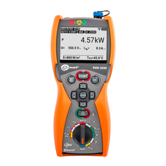
Page 29: Measurement Of Operating Current And Power
Enter the measurement range of C-PV clamps ▼ ▪ 400 A according to the algorithm and according to the rules described in general parameters setting. Reset the clamps (sec. 3.6). Connect the meter. DC side measurement, AC side measurement, PVM-1020 – USER MANUAL... - Page 30 If a voltage and current clamp connection error is detected, i.e. if the measured voltage is DC and the current is AC (or vice versa), the power P will be displayed with a ques- tion mark indicating this error. That kind of result cannot be saved to the memory. PVM-1020 – USER MANUAL...
-
Page 31: Resetting C-Pv Clamps
Alternatively, set the DC ZERO knob on the housing of the clamps to make the current readings as close to zero as possible. However, it is recommended to zero the clamps in the meter according to the procedure described above. PVM-1020 – USER MANUAL... -
Page 32: Low-Voltage Measurement Of Resistance
R CONT button to enter the auto-zeroing mode. Short the test leads. Activate the autozeroing by pressing the START button. After completion of autozeroing, the meter auto- matically switches to the "ready form measure- ment" mode. PVM-1020 – USER MANUAL... -
Page 33: Low-Current Measurement Of Resistance
Immediately disconnect the meter from the tested ob- ject (both leads)! 3.7.2 Low-current measurement of resistance Turn on the meter. Set the rotary switch of function selection at R The meter is ready for measurement. PVM-1020 – USER MANUAL... - Page 34 The tested object is live. The measurement is blocked. Immediately disconnect the meter from the tested ob- ject (both leads)! The test leads compensation is activated for low-voltage resistance measurements. Automatic measurement activation. >1999 Ω Measuring range is exceeded. PVM-1020 – USER MANUAL...
-
Page 35: Measurement Of Continuity Of Protective Conductors And Equipotential Bondings With ±200 Ma Current
21 Ω. The measurement may be also triggered with START button. Read the measurement result. The result is the arithmetic mean of the values of two measurements at a current of 200 mA with opposite polarities R and R PVM-1020 – USER MANUAL... - Page 36 Possible causes: interferences on the measured object too large, instability of the object or connections of the meter with this object (insecure galvanic connections). >1999 Ω Measuring range is exceeded. PVM-1020 – USER MANUAL...
-
Page 37: Diode Test With 200 Ma Current
(in the forward di- rection) is shown. Connect test leads according to the drawing. The polarity when connecting the diode does not matter - the meter will automatically set it before taking the measurement. Press START. PVM-1020 – USER MANUAL... - Page 38 perform a blocking diode test with 1000 V and save it to the same cell. If parameters are saved in the cell for the first time, no warning about data overwriting is be dis- played. PVM-1020 – USER MANUAL...
-
Page 39: Test Of Blocking Diode With 1000 V Voltage
The polarity when connecting the diode does not matter - the meter will automatically set it before taking the measurement. Press START. WARNING During the measurement of the U parameters, the meter generates dangerous measuring voltage of 1000 V. PVM-1020 – USER MANUAL... - Page 40 perform a blocking diode test with 1000 V and save it to the same cell. If parameters are saved in the cell for the first time, no warning about data overwriting is be dis- played. PVM-1020 – USER MANUAL...
-
Page 41: Memory Of Measurement Results
The meter is in the memory storing mode. Select an object and a cell according to sec 4.2 or leave the current one. The cell is empty. The cell contains the result of the same type which is to be entered. PVM-1020 – USER MANUAL... - Page 42 Complete set of results (main result and supplementary results) for a given measuring function, preset measurement settings, date and time of the measurement are stored in the memory. Additional data from the IRM-1 Irradiance Meter can also be saved. PVM-1020 – USER MANUAL...
-
Page 43: Changing The Cell And Bank Number
The cell number is flashing. To change the number of the bank/cell which con- tent you want to see press SET/SEL and then ▲▼ . If the bank or cell number is flashing - it may be changed. PVM-1020 – USER MANUAL... - Page 44 SC STC E, T +, R +, I ISO~ CONT CONT or P , U, I or P , U, I , P , E E, T or P~, U, I or P~, U, I E, T PVM-1020 – USER MANUAL...
-
Page 45: Deleting Memory Data
Press ENTER. A prompt for confirming deletion is shown. Press ENTER to start deleting or ESC to abort. When deletion is complete, the meter generates three short beeps and sets the cell number to "1". PVM-1020 – USER MANUAL... -
Page 46: Deleting The Entire Memory
Press ENTER. A prompt for confirming deletion is shown. ▼ Press ENTER to start deleting or ESC to abort. When deletion is complete, the meter generates three short beeps and sets the cell number to "1". PVM-1020 – USER MANUAL... -
Page 47: Communication
In order to ensure the communication of the meter with a computer, Bluetooth module is required with an additional software. A program that may be used for this purpose is Sonel Reader. It allows users to read and display the measurement data stored in the meter memory. Software may be down- loaded free from the manufacturer's website: www.sonel.pl. -
Page 48: Troubleshooting
Batteries / rechargeable batteries discharged. Replace batteries or recharge rechargeable batteries. The me- ter switches off automatically. Measurements performed with an insufficient supply voltage will be at risk of additional errors which the user is unable to evaluate. PVM-1020 – USER MANUAL... -
Page 49: Replacing The (Rechargeable) Batteries
The battery temperature increase is a signal to stop the charging and is typical. In addition to faster temperature increase of a battery which will not be fully charged, charging at high ambient temperatures results, however, in a reduced life. PVM-1020 – USER MANUAL... -
Page 50: Cleaning And Maintenance
Used electronic equipment shall be sent to the collection point according to the Used Electric and Electronic Equipment Act. Before sending the instrument to the collection point, do not dismantle any parts by yourself. Observe local regulations on disposal of packagings and used batteries. PVM-1020 – USER MANUAL... -
Page 51: Technical Data
Accuracy of generated voltage (R Detection of a dangerous voltage before commencing a measurement Discharging the object tested Measurement of voltage on terminals "+", "–" within the range of: 0…440 V Test current <2 mA PVM-1020 – USER MANUAL... -
Page 52: Measurement Of Insulation Resistance
Display range Resolution Accuracy Obliczana na podstawie 0…I mA, μA, nA Lmax wskazań rezystancji – maximum current at short circuit of leads, Lmax resolution and units result from the measurement range of individual insulation resistance. PVM-1020 – USER MANUAL... -
Page 53: Measurement Of Operating Current And Power
Compensation of test leads resistance 11.1.9 Converting measurement results to STC conditions The conversion of the measurement result to STC conditions takes place only when the irradiance measured by the IRM-1 meter is within its measuring range. PVM-1020 – USER MANUAL... -
Page 54: Other Technical Specifications
CAT III 600 V (CAT IV 150 V) to ground or CAT II 600 V DC to ground. Markings and symbols indi- cated on the instrument are to be considered valid when using it at altitude ≤2000 m. PVM-1020 – USER MANUAL... -
Page 55: Accessories
L4 carrying case – WAFUTL4 √ √ user manual – PVM-1020 √ user manual – IRM-1 √ √ factory calibration certificate – PVM-1020 √ factory calibration certificate – IRM-1 √ √ 4x AA 1.5 V battery √ √... -
Page 56: Optional Accessories
PV panels perature of PV panels and the diance meter WAPOZUCHPV ambient temperature (only PVM-1020 KIT) WASONTPV Mounting clamp for mounting kit WAZACPV Black Yellow Pin probe 1 kV (bana- na socket) WASONBLOGB1 WASONYEOGB1 PVM-1020 – USER MANUAL... -
Page 57: Manufacturer
AGT-32P WAADAAGT16P WAADAAGT32P 5-lead version, 63 A AGT-63P WAADAAGT63P "SONEL Reports PLUS" - software for generating measurement re- Software ports WAPROREPORTSPLUS Calibration certificate without accreditation 13 Manufacturer The manufacturer of the equipment and provider of service during and past the warranty period: SONEL S.A. -
Page 58: Laboratory Services
National Metrological Institute. According to ILAC-G24 „Guidelines for determination of calibration intervals of measuring instru- ments”, SONEL S.A. recommends periodical metrological inspection of the instruments it manufac- tures no less frequently than once every 12 months. - Page 59 MEASUREMENT MESSAGES Measurements Test voltage is present on terminals of the meter. You must consult the manual. Discharging the object Activation of current limit. The symbol displayed is accompanied by a continuous beep. Interference voltage occurs on the tested object. Measurement is possible but may be burdened with additional uncertainty.
Need help?
Do you have a question about the PVM-1020 and is the answer not in the manual?
Questions and answers