
Related Manuals for Sonel PQM-700


Summary of Contents for Sonel PQM-700
-
Page 1: Operating Manual
OPERATING MANUAL POWER QUALITY ANALYZER PQM-700 SONEL SA ul. Wokulskiego 11 58-100 Świdnica Poland Version 1.07 06.10.2017... - Page 2 Due to continuous product development, the manufacturer reserves the right to make changes to functionality, features and technical parameters of the analyzers. This manual describes the firm- ware version 1.07 and the Sonel Analysis v4.0.0 software.
-
Page 3: Table Of Contents
2.12 Firmware update ................... 25 2.12.1 Automatic update ....................25 2.12.2 Manual update ....................26 "Sonel Analysis" software ..............26 Design and measurement methods ............ 27 Voltage Inputs....................27 Current inputs ....................27 4.2.1 Digital integrator ....................27 Signal sampling .................... 28 PLL synchronization .................. - Page 4 Power Quality - a guide ................ 43 Basic Information ..................43 Current measurement ................... 44 6.2.1 Current transformer clamps (CT) for AC measurements ........44 6.2.2 AC/DC measurement clamps ................44 6.2.3 Flexible current probes ..................45 Flicker ......................45 Power measurement ..................
- Page 5 Standard equipment (non-US model version) ..........75 Standard equipment (US model version) ............75 Optional accessories ..................76 8.3.1 C-4(A) current probe ................... 76 8.3.2 C-5(A) current probe ................... 78 8.3.3 C-6(A) current probe ................... 80 8.3.4 C-7(A) current probe ................... 81 8.3.5 F-1(A), F-2(A), F-3(A) current probes ..............
-
Page 6: General Information
Australian standards municipal waste UL/cUL Safety Certification Mark The PQM-700 (US model) analyzer has been investigated and certified by Underwriters Labora- tories (UL) in accordance with the following Standards: UL 61010-1, 3rd Edition, May 11, 2012, Revised July 15 2015,... -
Page 7: Safety
1 General Information Safety Warning To avoid electric shock or fire, you must observe the following guidelines: Before you proceed to operate the analyzer, acquaint yourself thoroughly with the pre- sent manual and observe the safety regulations and specifications provided by the pro- ducer. -
Page 8: General Characteristics
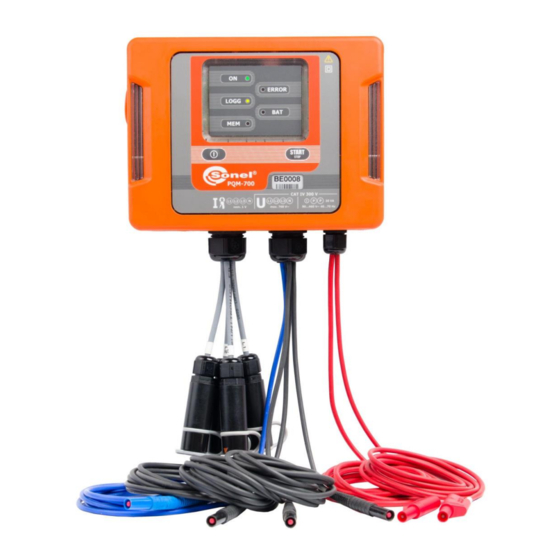
PQM-700 Operating Manual General characteristics Power Quality Analyzer PQM-700 (Fig. 1) is a high-tech device providing its users with a com- prehensive features for measuring, analysing and recording parameters of 50/60 Hz power net- works and power quality in accordance with the European Standard EN 50160. The analyzer is fully compliant with the requirements of IEC 61000-4-30:2009, Class S. -
Page 9: Power Supply Of The Analyzer
The user interface consists of five LEDs and 2 buttons. The full potential of the device may be released by using dedicated PC software Sonel Analysis. Communication with a PC is possible via USB connection, which provides the transmission speed up to 921.6 kbit/s... -
Page 10: Tightness And Outdoor Operation
Tightness and outdoor operation PQM-700 analyzer is designed to work in difficult weather conditions – it can be installed directly on electric poles. Two bands with buckles and two plastic fasteners are used for mounting the ana- lyzer. The fasteners are screwed to the back wall of the housing, and bands should be passed through the resulting gaps. -
Page 11: Mounting On Din Rail
5 W. Due to the characteristics of the built-in lithium-ion rechargeable battery, the process of charging is blocked when the battery temperature is outside the range of 0C…60C (in such case, Sonel Analysis software indicates charging status as "charging suspended"). -
Page 12: Measured Parameters
Some of the unique features of this device make it distinguishable from other similar analyzers available in the market. Tab. 1 presents a summary of parameters measured by PQM-700, depending on the mains type. - Page 13 1 General Information Tab. 1. Measured parameters for different network configurations. 3-phase triangle Network type, 2-phase 3-phase wye with N, phase 3-phase wye without N, channel Ʃ L1/A L2/B L3/C N Ʃ Ʃ Parameter L1/A N L1/A L2/B N L12/AB L23/BC L31/CA ...
-
Page 14: Compliance With Standards
PQM-700 Operating Manual Compliance with standards PQM-700 is designed to meet the requirements of the following standards. Standards valid for measuring network parameters: IEC 61000-4-30:2009 – Electromagnetic compatibility (EMC) - Testing and measurement techniques - Power quality measurement methods, IEC 61000-4-7:2002 –... -
Page 15: Operation Of The Analyzer
2 Operation of the analyzer 2 Operation of the analyzer Buttons The keyboard of the analyzer consists of two buttons: ON/OFF and START/STOP . To switch-on the analyzer, press ON/OFF button. START/STOP button is used to start and stop recording. Signalling LEDs The analyzer is equipped with five LEDs that indicate different operating states: ... -
Page 16: Auto-Off
To connect to the analyzer, enter its PIN code. The default code is 000 (three zeros). The PIN code may be changed using Sonel Analysis software. When wrong PIN is entered three times in a row, data transmission is blocked for 10 minutes. -
Page 17: Indication Of Connection Error
USB cable to your PC (USB slot in the device is located on the left side and is secured with a sealing cap). Before connecting the device, install Sonel Analysis software with the drivers on the computer. Transmission speed is 921.6 kbit/s. -
Page 18: Taking Measurements
PQM-700 Operating Manual Taking measurements 2.8.1 Start / stop of recording Recording may be triggered in three ways: immediate triggering - manually by pressing button after configuring the meter from a PC, LOGG LED is lit, scheduled triggering - according to time set in the PC. The user must first press button to enter recording stand-by mode;... -
Page 19: Measuring Arrangements
2 Operation of the analyzer Tab. 3. Approximate recording times for a few typical configurations. System Approximate type Waveforms recording Configuration Averaging Event wave- (current Events after averag- time with 2GB mode/profile time forms measure- ing period allocated ment on) space ... - Page 20 - in most types of passive receivers active power is positive. When clamps are incorrectly connected, it is possible to change their polarity using Sonel Analysis software. The following figures show schematically how to connect the analyzer to the tested network depending on its type.
- Page 21 2 Operation of the analyzer Fig. 6. Wiring diagram – 2-phase. Fig. 7. Wiring diagram – 3-phase wye with a neutral conductor.
- Page 22 PQM-700 Operating Manual Fig. 8. Wiring diagram – 3-phase wye without neutral conductor. Fig. 9. Wiring diagram – 3-phase delta.
- Page 23 2 Operation of the analyzer Fig. 10. Wiring diagram – 3-phase delta (current measurement using Aron method). Fig. 11. Wiring diagram – 3-phase wye without neutral conductor (current measurement using Aron method).
- Page 24 PQM-700 Operating Manual Fig. 12. Wiring diagram – indirect system with transducers – wye configuration. Fig. 13. Wiring diagram – indirect system with transducers – delta configuration.
-
Page 25: Key Lock
Firmware of the analyzer must be regularly updated in order to correct discovered errors or introduce new functionalities. When the firmware is updated, check whether a new version of Sonel Analysis (and vice versa) is available, if yes – proceed with the upgrade. -
Page 26: Manual Update
7. NOTE: After a successful update, it is necessary to program the analyzer at least once before starting recording, in order to avoid inconsistencies in the recorded data. 3 "Sonel Analysis" software Sonel Analysis is an application required to work with PQM-700 analyzer. It enables the user configure the analyzer, ... -
Page 27: Design And Measurement Methods
The PQM-700 analyzer firmware includes a digital filter which is to remove totally the DC voltage component. The filtered signal is subjected to digital inte- gration. -
Page 28: Signal Sampling
PQM-700 Operating Manual measurement error can be described with the following relationship Power measurement error ≈ phase error (in radians) × tan(φ) × 100 % where tan(φ) is the tangent of the angle between the fundamental voltage and current components. -
Page 29: Frequency Measurement
5 Hz. As the PQM-700 analyzer collects 2048 samples per measuring window (for 50 Hz and 60 Hz), this fulfills the requirement of Fast Fourier Transform that the number of samples subjected to trans- formation equals a power of 2. -
Page 30: Event Detection
The resultant amplitude is calculated with the RMS method. Event detection The PQM-700 analyzer gives a lot of event detection options in the tested mains system. An event is the situation when the parameter value exceeds the user-defined threshold. The fact of event occurrence is recorded on the memory card as an entry which includes: ... - Page 31 4 Design and measurement methods Tab. 4. Event threshold types for individual parameters Parameter Interruption Swell Minimum Maximum RMS voltage DC voltage Frequency CF U Voltage crest factor Voltage negative sequence unbalance ...
- Page 32 PQM-700 Operating Manual no event end time, extreme value is only for the period until the stop of recording, average value is not given, only the beginning waveform is available for RMS voltage or current related events.
-
Page 33: Calculation Formulas
5 Calculation formulas 5 Calculation formulas One-phase network One-phase network Parameter Method of calculation Designa- Name Unit tion �� = √ �� ∑ �� �� �� �� Voltage (True RMS) ��=1 where U is a subsequent sample of voltage U M = 2048 for 50 Hz and 60 Hz ��... - Page 34 PQM-700 Operating Manual cos �� = ������ = cos(�� − �� �� �� where is an absolute angle of the fundamental com- Displacement power fac- ponent of voltage U is an absolute angle of the fundamental component of current I ��...
- Page 35 5 Calculation formulas �� �� = ∑ �� (��)��(��) ��+ ��=1 �� ( �� ) ������ �� ( �� ) > 0 �� (��) = { 0 ������ �� ( �� ) ≤ 0 �� �� = ∑ �� (��)��(��) ��−...
-
Page 36: Split-Phase Network
PQM-700 Operating Manual �� = ∑ �� ( �� ) ��(��) �� �� ��=1 where: i is subsequent number of the 10/12-period measure- Apparent energy ment window S(i) represents apparent power S calculated in i-th measuring window T(i) represents duration of i-th measuring window (in... - Page 37 5 Calculation formulas �� �� = ∑ �� (��)��(��) ����+������ ��������+ ��=1 ( �� ) ������ �� ( �� ) > 0 �� �������� �������� �� (��) = { ��������+ ( �� ) ≤ 0 0 ������ �� �������� �� ��...
-
Page 38: 3-Phase Wye Network With N Conductor
PQM-700 Operating Manual 3-phase wye network with N conductor 3-phase wye network with N conductor (parameters not mentioned are calculated as for single-phase) Parameter Method of calculation Designa- Name Unit tion �� = �� + �� + �� Total active power ������... - Page 39 5 Calculation formulas Total reactive energy of Q1+tot fundamental component varh formula same as in split-phase system Q1-tot (consumed and supplied) �� ( �� ) ��(��) �� = ∑ �� �������� �� ��=1 where: i is subsequent number of the 10/12-period measure- Total apparent energy Stot ment window...
-
Page 40: 3-Phase Wye And Delta Network Without Neutral Conductor
PQM-700 Operating Manual �� (�� + ���� + �� �� ��1 ��1 ��1 �� = ������(�� RMS value of positive where I are vectors of fundamental current current sequence components I Operator mag() indicates vector module �� (�� + ��... - Page 41 5 Calculation formulas = √ �� �� + �� ���� �� ��1 where: �� = 3�� �� ��1 ��1 ��1 Effective apparent distor- �� + �� + �� ����1 ����1 ����1 = √ tion power �� ��1 �� + �� + ��...
-
Page 42: Methods Of Parameter's Averaging
PQM-700 Operating Manual Methods of parameter‘s averaging Method of averaging parameter Parameter Averaging method RMS Voltage DC voltage arithmetic average Frequency arithmetic average Crest factor U, I arithmetic average Symmetrical components U, I Unbalance factor U, I calculated from average values of symmetrical components... -
Page 43: Power Quality - A Guide
6 Power Quality - a guide 6 Power Quality - a guide Basic Information The measurement methodology is mostly imposed by the energy quality standards, mainly IEC 61000-4-30. This standard, introducing precise measurement algorithms, ordered analyzers mar- ket, allowing customers to easily compare the devices and their results between the analyzers from different manufacturers. -
Page 44: Current Measurement
Despite such drawbacks, the CT clamps are presently the most widely used non-invasive alter- nating current (AC) measurement method. The following CT clamps can be used with the PQM-700 analyzers to measure alternating cur- rents: C-4(A), rated range 1000 A AC, ... -
Page 45: Flexible Current Probes
F-3(A), with coil circumference 45 cm. All these probes have identical electrical parameters. The peak current which can be measured after connecting to PQM-700 is about 10 kA (the limitation is due to the properties of the input channels, and not the probe itself). -
Page 46: Power Measurement
PQM-700 Operating Manual offsets these fluctuations almost totally. The tests have proved that maximum arduousness occurs at the frequency of about 9 changes per second. The most sensitive light sources are traditional incandescent bulbs with tungsten fila- ment. Halogen bulbs, which filaments have much higher temperature, have also much higher inertia which reduces the perceived brightness changes. -
Page 47: Reactive Power
U is RMS voltage, I is RMS current, and is the phase shift angle between the voltage and the current. The PQM-700 analyzer calculates the active power directly from the integral formula, using sampled voltage and current waveforms: ��... - Page 48 PQM-700 Operating Manual nonactive power designated as N. Reactive power has been limited only to the fundamental com- ponent and designated Q This standard is the last document of this type issued by recognized organization which was to put the power definition issues in order. It was even more necessary as the voices had been ap- pearing in scientific circles for many years that the power definitions used so far may give erroneous results.
- Page 49 6 Power Quality - a guide And then, is really D a measure of such distortion? Unfortunately, also in this case the Bude- anu’s power theory fails. It has been proven that the distortion power can be equal to zero in a situation when voltage is distorted in relation to current waveform, and vice versa, the distortion power can be non-zero at total absence of distortion.
-
Page 50: Reactive Power And Three-Wire Systems
PQM-700 Operating Manual This component explains the situation in which an unbalanced three-phase load of a purely resistive character results in the power factor less than one. Such load does not have the reactive power Q, and still the results from the power triangle S, P, Q are totally different (the Budeanu’s power theory with its distortion power could not explain this situation either –... -
Page 51: Reactive Power And Reactive Energy Meters
6 Power Quality - a guide allowed only after a clear reservation that the indicated value is not a result of actual measurement, but only an approximated value. 6.4.4 Reactive power and reactive energy meters Reactive energy meters are devices unknown to the household users who for settlements with energy suppliers use the meters of active energy expressed in Wh or kWh. -
Page 52: Apparent Power
PQM-700 Operating Manual The higher the harmonics content, the higher difference in readings, and of course, as a con- sequence, other fees for measured energy. As it has been signaled before, the reactive power measurement in unbalanced three-wire sys- tems with traditional meters is subject to an additional error caused by creation of a virtual zero inside the meter which has little to do with actual zero of the receiver. -
Page 53: Distortion Power D
6 Power Quality - a guide The IEEE 1459 standard gives the following formulas. In three-wire systems: �� + �� + �� = √ �� �� �� �� �� �� + �� + �� ���� ���� ���� = √ �� ��... -
Page 54: Power Factor
PQM-700 Operating Manual where U and I are effective values of fundamental components of phase-to-neutral voltage and current. 6.4.7 Power factor True Power Factor or Power Factor (TPF or PF) is the value which takes into account also the presence of higher harmonics. For sinusoidal systems, it is equal to Displacement Power Factor (DPF), popular cos. - Page 55 6 Power Quality - a guide showed very high RMS current. Explanation of this phenomenon is however rather simple. In this example, the designer did not take into consideration two circumstances: in systems with distorted waveforms, the higher harmonics might not zero in the neutral conductor, and quite to the contrary, they may sum up, and secondly, the skin effect and high harmonic currents additionally contributed to the neutral conductor heating.
-
Page 56: Harmonics Characteristics In Three-Phase System
PQM-700 Operating Manual 6.5.1 Harmonics characteristics in three-phase system In three-phase systems, the harmonics of given orders have a particular feature which is shown in the table below: Order Frequency [Hz] – – – Sequence (+ positive, – negative, 0 zero) The row “Sequence”... -
Page 57: Thd
– RMS waveform. Limitation of the number of harmonics used to calculate THD is conventional and is caused mainly by measuring limitations of the device. Because the PQM-700 is capable of measuring the harmonic components up to the 40 order, the harmonics up to the 40 order are used to calculate THD. - Page 58 PQM-700 Operating Manual vectors can be resolved to three groups of vectors: positive sequence, negative sequence and zero sequence. Fig. 18. Example of determination of positive sequence component. As an example, let us use the calculation of voltage positive sequence component.
-
Page 59: Detection Of Voltage Dip, Swell And Interruption
6 Power Quality - a guide – zero sequence symmetrical component, – positive sequence symmetrical component, – negative sequence symmetrical component. The most convenient method to calculate the symmetrical components and unbalance is using the complex number calculus. The vectors parameters are amplitude of the voltage (current) fun- damental component and its absolute phase shift angle. -
Page 60: Cbema And Ansi Curves
PQM-700 Operating Manual During the interruption, the analyzer remembers the minimum recorded voltage and the average voltage value. Swell is a state of increased voltage. The swell threshold is usually set at the level close to 110% of U The swell starts at the mo-... - Page 61 ANSI (American National Standards Institute). Both curves are pre- sented in Fig. 21. Sonel Analysis software provides the ability to modify the characteristic points of the curves allowing user to adjust them to individual requirements.
-
Page 62: Averaging The Measurement Results
10 minutes which gives “only” 1008 measurement results. Fig. 22 presents the method according to which the PQM-700 analyzer determines the average values at averaging intervals equal to or greater than 10 seconds with the 10-minute averaging time. - Page 63 6 Power Quality - a guide Fig. 23. Determining the averaging intervals shorter than 10 seconds (with the 3-second averaging). The method of average values determination for such periods is shown in Fig. 23. Here, we do not have synchronization with the real time clock. When a defined number of 10/12-period meas- urement is collected, the instantaneous averaging period is closed and a new one starts.
- Page 64 PQM-700 Operating Manual On the other hand, the power quality tests are usually made according to the EN 50160. In this case, the analysis is carried out over a longer period of time (e.g. 7 days), and therefore the chosen averaging time is also long - 10 minutes.
-
Page 65: Technical Specifications
Basic uncertainty is the uncertainty of a measurement instrument at reference conditions specified in Tab. 5. Provided uncertainties apply to PQM-700 without additional transformers and clamps. Abbreviations: m.v. – reference measured value, ... -
Page 66: Sampling And Rtc
PQM-700 Operating Manual Sampling and RTC Sampling and RTC A/D converter 16-bit Sampling rate 10.24 kHz for 50 Hz and 60 Hz Simultaneous sampling in all channels Samples per period 204.8 for 50 Hz; 170.67 for 60 Hz PLL synchronization 40..70Hz... -
Page 67: Frequency
7 Technical specifications CT clamps C-5(A) Additional uncertainty 0..1000 A 0.01% I 0,5..100 A: ≤ (1.5% + 1 A) (3600 A 100..800 A: ≤ 2.5% 800..1000 A AC: ≤ 4% 800..1400 A DC: ≤ 4% CT clamps C-6(A) 0..10 A 0.01% I Additional uncertainty 0,01..0.1 A: ... -
Page 68: Estimating The Uncertainty Of Power And Energy Measurements
Tab. 6 presents the phase difference error between the voltage and current harmonics for the PQM-700 analyzer (without clamps and transducers). Tab. 6. Phase error in the PQM-700 analyzer depending on the frequency Phase difference error Frequency range 0..200 Hz... - Page 69 Conditions: = 60 = 5% I Fundamental uncertainty equals ± √ 1.0 + Δ For the 0..200Hz frequency range, the PQM-700 phase error is < 1 . After substituting to the equation: ������ ( ��+���� ) ������(61°) �� = 100 (1 −...
-
Page 70: Flicker
PQM-700 Operating Manual 7.3.8 Flicker Flicker Ranges and conditions Resolution Basic uncertainty 10% within the values presented in (10 min), 0.4 ... 10 0.01 ≥ 80% U (2 h) for U tables of IEC 61000-4-15 standard 7.3.9 Unbalance Unbalance Ranges and conditions... -
Page 71: Event Detection Hysteresis
7 Technical specifications Distortion power D / Apparent dis- Depending on the con- Basing on 10/12-period value tortion power S figuration (min, max) 0…1 Power Factor PF (min, max) Basing on 10/12-period value Displacement power factor cosφ/ 0…1 Basing on 10/12-period value DPF (min, max) tanφ... -
Page 72: Power Supply,Battery And Heater
PQM-700 Operating Manual Instanta- Mean Minimum Maximum Recorded parameters neous value value value value RMS phase/phase-to-phase (depending on the type of system) voltage U RMS phase-to-phase voltage U (only 3-phase wye with N and split-phase systems) ... -
Page 73: Supported Networks
7 Technical specifications Heater Heater temperature threshold (activation) +5C Heater power supply from internal AC/DC adapter Heater power max. 5 W Supported networks Types of supported networks (directly and indirectly) 1-phase 1-phase with a neutral conductor (terminals: L1/A, N) 2-phase (split-phase) Split phase with a neutral conductor (terminals: L1/A, L2/B, N) 3-phase wye with N, 3-phase wye with a neutral conductor (terminals: L1/A, L2/B, L3/C, N) -
Page 74: Safety And Electromagnetic Compatibility
PQM-700 Operating Manual 7.13 Safety and electromagnetic compatibility Safety and EMC Compliance with IEC 61010-1, 3 Edition Measurement Category IV 300 V (Voltage measurement inputs) III 600 V II 760 V pollution class 2 Overvoltage Category IV 300 V (AC/DC Power adapter) -
Page 75: Equipment
mains plug with banana inputs (L1/A and N) for connecting the analyzer to socket in order to charge the battery – WAADAAZ1, software for data reading and analysing "Sonel Analysis", USB cable – WAPRZUSB, 2 GB microSD card, ... -
Page 76: Optional Accessories
F-2A for current up to 3 kA AC (length: 80 cm) – WACEGF2AOKR, flexible clamps F-3A for current up to 3 kA AC (length:45 cm) – WACEGF3AOKR, – battery (replaceable by SONEL after-sale services) WAAKU11, phase splitter AC-16 – WAADAAC16, ... - Page 77 8 Equipment Warning Do not use the device on non-insulated conductors with a potential of more than 600 V in relation to the earth and a measurement category greater than III. Reference conditions Temperature +20…+26°C Humidity 20…75% RH ...
-
Page 78: A) Current Probe
Make sure the jaws are closed and there is no conductor inside them. Then, connect the probe to the analyzer and launch the Sonel Analysis software in the instantaneous values viewing mode (check if the measurement point is correctly configured for measurement with the C-5(A) probe). - Page 79 8 Equipment Technical specification Accuracy: 800…1000 A (AC) 0,5…100 A 100…800 A Current range 800…1400 A (DC) 1.5% + 1 A 2.5% 4% Basic uncertainty as % of measured value Phase error (45...65 Hz): Current 10…200 A 200…1000 A...
-
Page 80: A) Current Probe
PQM-700 Operating Manual maximum measured conductor diameter: 39 mm probe lead length: 1.5 m operating temperature: –10C…+55C humidity: 85% RH height: 2000 m electromagnetic compatibility: IEC 61000-6-3:2008 IEC 61000-6-2:2008 8.3.3 C-6(A) current probe... -
Page 81: A) Current Probe
8 Equipment ratio: 100 mV AC/1 A AC frequency range: 40 Hz...10 kHz insulation type: double, according to IEC 61010-1 measuring category acc. to IEC 61010-1: III 600 V, protection rating acc. to IEC 60529: IP 40, with open jaws: IP 30 ... -
Page 82: A), F-2(A), F-3(A) Current Probes
PQM-700 Operating Manual Basic Frequency Phase error uncertainty 2 45…65 Hz ±0,5% ±0.1 mV 40 Hz…1 kHz ±1.0% ±0.2mV unspecified ratio: 5mV AC/1 A AC 11 output impedance type of insulation: double, according to IEC 61010-1 ... - Page 83 8 Equipment Reference conditions Temperature: +18…+22°C Conductor position: centered in relation to the probe loop Continuous magnetic field: earth field (<40 A/m) Alternating magnetic field: none External electric field: none Technical specification Rated measuring range: 1 A…3000 A (±10000A peak for 50 Hz) ...
-
Page 84: Other Information
PQM-700 Operating Manual 9 Other information Cleaning and maintenance Note Use only the maintenance methods presented by the manufacturer in this manual. Clean the analyzer casing with a wet cloth, using generally available detergents. Do not use any solvents and cleaning media which could scratch the casing (powder, paste, etc.). - Page 85 Notes...
Need help?
Do you have a question about the PQM-700 and is the answer not in the manual?
Questions and answers