Advertisement
Quick Links
Analizador de calidad de energia
Sonel PQM-701
CALIDAD DE ENERGIA
Los problemas causados por la pobre calidad de
energía son extremadamente serios y pueden
ocasionar dificultades en los clientes, tal vez
ocasionen pérdidas ecónomicas a ellos.
El reporte más importante de calidad de energía incluye:
Elevadas armónicas en el sistema principal,
Pozos de Voltaje e interrupciones,
Eventos cortos pero de gran amplitud,ondulaciones de voltaje.
Parpadeo
Desbalance
Advertisement

Related Manuals for Sonel PQM-701


Summary of Contents for Sonel PQM-701
- Page 1 Analizador de calidad de energia Sonel PQM-701 CALIDAD DE ENERGIA Los problemas causados por la pobre calidad de energía son extremadamente serios y pueden ocasionar dificultades en los clientes, tal vez ocasionen pérdidas ecónomicas a ellos. El reporte más importante de calidad de energía incluye: Elevadas armónicas en el sistema principal, Pozos de Voltaje e interrupciones, Eventos cortos pero de gran amplitud,ondulaciones de voltaje. Parpadeo Desbalance...
- Page 2 Distorsión de Voltaje y corriente es causada en general por receptores no lineales que toman la corriente no sinousoidal. Lo más frecuente fuente de receptores no lineales incluye: Equipos conductores-Inversores, sistemas de arranque suave de motores, rectificadores controlados y no controlados, fuentes Hornos eléctricos-Hornos de inducción de alta frecuencia,hornos de arco, calentadores de inducción, máquinas soldadoras,soldadoras de presión(láminas, film,etc), microndas, láser. Iluminación-Lámpara de descarga, tubos fluorescentes, lámparas de arco, Electrodomésticos- Computadoras, servidores, monitores, UPS, copiadoras, aire acondicionado. ELEVADAS ARMÓNICAS EN LA RED Todos los instrumentos mencionados arriba toman la corriente de manera no lineal.causando la formación de las armónicas. Como se ha mencionado ya los equipos de este tipo hay cada vez más en nuestro alrededor. La práctica demuestra que las armónicas arriba de 20 ocurren raras veces y casi siempre tienen los valores pequeños, por eso como estandár de los medidores que analizan los armónicos tomamos al menos 25 armónicos pero a veces existen analizadores que saben registrar hasta 50 armónicas y más. Armónicas elevadas pueden causar diferentes efectos adversos en la red, como: sobrecalentamiento de los cables o las vías ferroviarias neutrales, las pérdidas en los transformadores, incluyendo sus daños en sistemas de potencia de compensación pueden ocurrir daños de condensadores durante resonancia causando explosión, las pérdidas en los motores, no sólo relacionados con energía pero también con desgaste mecánico más rápido, problemas de conexón especialmente en cuanto a dipositivos de corriente residual, funcionamiento malo de los equipos eléctronicos junto con dañarlos, problemas en pasar y analizar los datos.
- Page 3 Fig 1. Paso desviado de onda de corriente a través de la lámpara fluorescente POZOS DE VOLTAGE E INTERRUPCIONES Pozo de tensión es una corta disminución por debajo de valor de la tensión en el 90% - 1% de rango de voltaje declarado. Duración de este evento es convencionalmente basado en el rango 10 ms - 1 min. La razón de pozos de tensión está principalmente relacionada en conectar las cargas grandes a la red, en el lado de ambos, tanto el proveedor de energía como el consumidor. Este fenómeno es más frecuente cuando la impedancia de línea es alta (es decir, en las zonas rurales que tienen pequeñas líneas aéreas de la sección transversal de voltage baja a su vez aumentando el poder de consumo de los consumidores). La causa menos frecuente de pozos de tensión es un cortocircuito en los sistemas de distribución y también en el cableado eléctrico de los consumidores. PARPADEO (FLICKER) En términos de calidad de la energía, flicker significa cambios periódicos de la intensidad luminosa como consecuencia de las fluctuaciones de voltaje suministrada a las bombillas eléctricas. Este fenómeno provoca un deterioro del bienestar, el fastidio, a veces dolor de cabeza, que es arduo para la gente. Las pruebas han demostrado que la dureza máxima ocurre en la frecuencia de approx. 9 cambios por segundo. Las fuentes de luz más sensibles son las bombillas incandescentes tradicionales con filamento de tungsteno. Las lámparas fluorescentes tienen la mejor "resistencia" de parpadeo. El parpadeo está causado por la caída de tensión como resultado de la...
- Page 4 DESBALANCE. Desbalance es el termino relacionado con sistema trifasico puede referirse a: Desbalance de voltage de alimentacion, Desbalance de corriente de carga, Desbalande de receptor En los sistemas de tres fases, desbalance de la tensión (corriente) se produce cuando los valores de tres componentes de voltajes (corrientes) son diferentes y / o los ángulos entre las fases individuales no son iguales a 120 grados. These phenomena are particularly dangerous for three-phase motors, in which even a slight voltage unbalance can cause current unbalance that is many times larger. In such situation, the motor torque is reduced, heat losses in windings increase, and mechanical wear is faster. The unbalance also has an unfavorable effect on power supply transformers. The most frequent reason of unbalance is uneven load on individual phases. A good example is connecting to three-phase systems of large one-phase loads, such as railway traction motors. In normal conditions, such as LV lines in the rural areas mentioned above, the unbalance can aggravate voltage dips and flicker. PQM-701 ANALYZER...
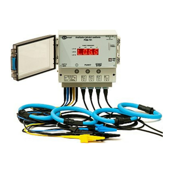
- Page 5 Fig. 2. Power Quality Analyzer PQM-701 The events described above constitute a part of problems related to power quality. In order to eliminate hazards to the mains systems and equipments which receive power from them, we need to discover the phenomena which happen in the mains and we must be able to interpret them correctly. To do this, we need to have an analyzing tool. The PQM-701 analyzer is such a tool. The analyzer is intended for a wide spectrum of users who need to control the power quality with a portable device. It can be used in practically all types of mains from 110V to 690V, directly or indirectly through transducers. It can be operated in one-phase systems, split- phase systems, 3- and 4-wire three-phase wye systems, or three- phase delta systems. Therefore, the PQM-701 is an instrument which can be used in professional power engineering, by maintenance departments in industrial plants, or by people who provide mains analysis services. The analyzer is placed in a simple, robust casing with IP65 ingress protection rating. Due to the casing design, the analyzer can be installed practically anywhere, outdoors and indoors. The analyzer has an built-in heater which is activated automatically when the temperature inside the casing drops below 0°C. This ensures optimum operating conditions for the analyzer electronic circuits. With special...
- Page 6 The analyzer has five voltage input terminals, marked L1/A, L2/B, L3/C, N and PE, and the N terminal (neutral conductor) is shared. The range of voltages measured by four measuring channels is ±1150V maximum.Current is measured by means of four current inputs to which several types of current clamps can be connected, such as flexible clamps F-1, F-2, F-3 with the 3000A nominal range (the only difference between them is the coil size) and the C-4 clamp (range 1000A AC), C-5 clamp (range 1000A AC/DC) and C-6 clamp (range 10A AC). The instrument is equipped with a high-capacity removable SD memory card (Secure Digital). When the recording is completed, the card can be removed from the analyzer and the data can be transferred quickly to the computer by means of an external card reader and the software which is included in the kit. The data can also be read by two communication links: USB or wireless transmission. Power quality analyzer PQM-701 is an advanced product for comprehensive measurements, analysis and recording of the parameters of the 50/60 Hz mains systems and of the power quality according to the EN 50160. The PQM-701 records current and voltage crest factors, frequency values in the 40Hz - 70Hz range, active power, apparent power, distortion power, reactive power with determination of its type (capacitive or inductive). Two methods can be used for power measurements: Budeanu or IEEE 1459. Such parameters as active energy, reactive energy, apparent energy, power factor, cosφ and tanφ are of course recorded as well. The next values which we can analyze are transformer overload level caused by harmonic distortion (K-factor), current and voltage harmonics up to the 50th, current and voltage THD, short-term and long-term flicker, voltage and current unbalance. Recorded also are all events, such as voltage dips, swells and interruptions with waveforms (also for currents). After each averaging period, the analyzer can record snapshot waveforms for current and voltage. All these functions allow a comprehensive analysis of phenomena in the tested electrical mains system. The PQM-701 is supplied with all necessary connection and power...
- Page 7 Fig. 3. PQM-701 kit with standard accessories Due to very wide range, the clamps are optional equipment to be chosen by the users according to their particular needs. The user has a choice of current transformer clamps C-4 up to 1000A AC, C-6 up to 10A AC, Hall-sensor clamp C-5 up to 1000A AC/DC and other flexible clamps: F-1 (dia 40cm), F-2 (dia 25cm), up to 3kA AC. Optional equipment includes also the OR-1 adapter for wireless transmission. Sonel Analysis software...
- Page 8 A key component which determines the device usefulness in the analyses is the Sonel Analysis software without which the instrument will not work. The software allows configuring individual measuring functions, analysis of data collected during the recording process, and observation of instantaneous mains parameters and it is available in english. The software allows full configuring of the analyzer in terms of recorded parameters, protections, measurement points preferences (due to four different configurations, the analyzer enables recording in four different points). From the software level, the user can set the recording trigger mode, set the recording time schedule, or configure the memory allocation to individual measurement points. The function of viewing the parameters measured by the PQM-701 in real time is totally independent of the recording function. The following can be viewed: current and voltage waveform plots for individual phases, current and voltage plots in function of time for individual phases, all values measured by the PQM-701 presented in tables, voltage and current phase shifts on phasor diagrams, current and voltage harmonics up to the 50th, plus harmonics active and reactive power values.
- Page 9 Fig. 4. Analyzer configuratio n The main software function is reading the data from the meters and data analysis. The user can view the measured data in tables, view the events with their oscillograms, create reports and various diagrams. The event screen gives the user extensive analysis options for all selected events. With the software, the user can print reports and diagrams. If hundreds of events have been recorded during a recording period, it is possible to mark those which for some reasons are more important for us than the others.
- Page 10 Fig. 5. Current voltage waveforms Fig. 6. Measured data...
- Page 11 Fig. 7. Event waveforms SUMMARY The PQM-701 with the software is an exceptionally useful power quality analyzer which can be used in all areas of power engineering, both in professional power engineering and at industrial plants. The instrument is resistant to ambient conditions, easy to operate, and features user-friendly software. The PQM-701 is an excellent alternative to existing analyzers, particularly in terms of price-to- performance ratio.
- Page 13 Fotos: Aleksander Jonczyk, Sonel S.A. Autor: Roman Domański, Marcin Szudniewski Sonel S.A.
Need help?
Do you have a question about the PQM-701 and is the answer not in the manual?
Questions and answers