Table of Contents
Advertisement
Quick Links
Advertisement
Table of Contents

Related Manuals for HIKOKI C 12FDHB


Summary of Contents for HIKOKI C 12FDHB
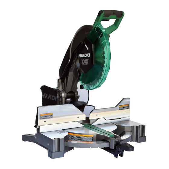
- Page 1 C 12FDHB Handling instructions...
- Page 2 Hazards that must be avoided to prevent bodily injury or machine damage are identifi ed by WARNINGS on the power tool and in this Instruction Manual. NEVER use this power tool in a manner that has not been specifi cally recommended by HiKOKI. MEANINGS OF SIGNAL WORDS WARNING indicates a potentially hazardous situations which, if ignored, could result in death or serious injury.
- Page 3 1) Work area safety b) Use personal protective equipment. Always a) Keep work area clean and well lit. wear eye protection. Cluttered or dark areas invite accidents. Protective equipment such as a dust mask, non- b) Do not operate power tools in explosive skid safety shoes, hard hat or hearing protection atmospheres, such as in the presence of used for appropriate conditions will reduce...
- Page 4 d) Store idle power tools out of the reach of b) Use clamps to support the workpiece whenever children and do not allow persons unfamiliar possible. If supporting the workpiece by hand, with the power tool or these instructions to you must always keep your hand at least 100 mm operate the power tool.
- Page 5 Without turning the tool “ON” and with no workpiece SPECIFIC SAFETY RULES FOR USE OF on the table, move the saw blade through a complete THIS POWER TOOL simulated cut to assure there will be no interference or WARNING danger of cutting the fence. k) Provide adequate support such as table The following specifi...
-
Page 6: Replacement Parts
9. Never lock the lower guard; always confi rm that it slides When servicing use only identical replacement parts. smoothly before using the tool. Repairs should be conducted only by a HiKOKI authorized 10. Never damage the power cord of the tool. service center. -
Page 7: Double Insulation For Safer Operation
DOUBLE INSULATION FOR SAFER OPERATION To ensure safer operation of this power tool, HiKOKI has adopted a double insulation design. “Double insulation” means that two physically separated insulation systems have been used to insulate the electrically conductive materials connected to the power supply from the outer frame handled by the operator. -
Page 8: Operation And Maintenance
OPERATION AND MAINTENANCE NOTE: The information contained in this Instruction Manual is designed to assist you in the safe operation and maintenance of the power tool. Some illustrations in this Instruction Manual may show details or attachments that diff er from those on your own power tool. - Page 9 LED light switch Trigger switch Carry handle Spindle lock 6 mm hex. bar wrench Dust port Bevel scale Miter detent override button Bevel lock handle Miter scale Angle block Indicator (for left bevel scale) Mounting hole Vice lock knob Fig. 2...
-
Page 10: Specifications
SPECIFICATIONS Compound Miter Saw C12FDHB Type Series commutator motor Power source Single-phase AC 50/60Hz Motor Voltage (Volts) Full-load current (Amp) LED light Outside Dia. 305 mm Applicable saw blade Hole Dia. 25.4 mm Maximum kerf 2.8 mm No load speed 4,300 /min Head Turntable... -
Page 11: Standard Accessories
Extension holder and Stopper (Code No. 377095) Crown molding Vise Ass’y (Code No. 339660) Crown molding Stopper (L) (Code No. 339730) Crown molding Stopper (R) (Code No. 339731) NOTE Accessories are subject to change without any obligation on the part of the HiKOKI. -
Page 12: Preparation Before Operation
APPLICATIONS Wood and aluminum sash. PREPARATION BEFORE OPERATION Make the following preparations before operating the power tool: Remove all packing materials attached or connected to the tool before attempting to operate Installation 247 mm 247 mm Base 8 mm bolt 9 mm 4 holes 259.75 mm 259.75 mm... - Page 13 Releasing the locking pin When the power tool is prepared for shipping, its Locking pin main parts are secured by a locking pin. Handle Move the handle slightly so that the locking pin can be disengaged. NOTE: Lowering the handle slightly will enable you to disengage the locking pin more easily and safely.
-
Page 14: Before Using
BEFORE USING Make sure the power source is appropriate for the tool. WARNING: Never connect the power tool unless the available AC power source is of the same voltage as that specifi ed on the nameplate of the tool. Never connect this power tool to a DC power source. Make sure the trigger switch is turned OFF. - Page 15 If the brake fails to engage frequently, depress and release the trigger switch to turn the tool on and off 4 or 5 times. If the brake still does not engage, have the tool serviced at a HiKOKI authorized service center.
-
Page 16: Before Cutting
BEFORE CUTTING Checking the saw blade lower limit position 6 mm depth Check that the saw blade can be lowered adjustment screw Hinge 49 mm to 50 mm below the table insert. When you replace a saw blade with a new one, adjust the lower limit position so that the saw blade will not cut the turntable or complete cutting cannot be done. - Page 17 Indicator (for right bevel scale) 6 mm set screw Set button Indicator (for left bevel scale) Press 6 mm hex. Angle socket screw (A) block (B) Angle block (A) 6 mm hex. socket Angle screw (B) block (A) Angle block (B) Fig.
- Page 18 Stopper for precision cutting ... (Stopper and holder are optional accessory) The stopper facilitates continuous precision Workpiece cutting in lengths of 290 mm to 460 mm. Stopper (Optional accessory) To install the stopper, attach it to the holder with the 6 mm wing bolt as shown in Fig. 11. Holder (Optional accessory) 6 mm...
- Page 19 Confi rmation for use of sub fence (L) (Fig. 12-b) WARNING: When left bevel angle cutting, loosen the 8 mm knob bolt, then slide the sub fence (L) outward. Failure to do so may result in the main body or saw blade coming into contact with the sub fence (L) and causing injury.
- Page 20 (3) Bevel angle of 48° (right and left) (Fig. 13-c) Rotate both angle block (A) and angle block (B) from A to direction B. After pulling out the sub fence, loosen the bevel lock handle and tilt the motor head to place either the 6 mm hex socket screw (A) (when tilted to the left) or the 6 mm hex socket screw (B) (when tilted to the right) on the base surface.
- Page 21 10. Miter detent override button (Fig. 14) The miter detent override button allows for the table to be micro adjusted, disengaging the positive detent stops feature. When a required miter angle is close to a positive detent stop, this override prevents the wedge on the miter arm from slipping into that detent slot on the base.
-
Page 22: Practical Applications
PRACTICAL APPLICATIONS WARNING: * To avoid personal injury, never remove or place a workpiece on the table while the tool is being operated. * Never place your limbs inside of the line next to warning sign while the tool is being operated. This may cause hazardous conditions (see Fig. - Page 23 Securing Workpiece WARNING: Always fi rmly clamp or vise to secure the workpiece to the fence or base; otherwise the workpiece might be thrust from the table and cause bodily harm. CAUTION: Always confi rm that the motor head (see Fig. 1) does not contact the vise assembly when it is lowered for cutting.
- Page 24 Cutting Operation As shown in Fig. 20 the width of the saw Adjusting line blade is the width of the cut. Therefore, slide the workpiece to the right (viewed from the operator’s position) when length ⓑ is desired, or to the left when length ⓐ is desired.
- Page 25 Miter cutting procedures (1) Unlock the turntable by lifting up on the miter lock handle. (2) While pressing down on the positive stop lock Indicator Miter scale button, grasp the miter lock handle and rotate the turntable left or right to the desired angle. Unlock Miter lock (3) Once the desired miter angle is achieved,...
- Page 26 NOTE: * Positive stop are provided at right and left of the 0° center setting, at 33.9° and 45° settings. Check that the bevel scale and the tip of the indicator are properly aligned. WARNING: * When the workpiece is secured on the left or right side of the blade, the short cut-off...
- Page 27 The table below shows the miter angle and the bevel angle settings that are ideal for the two crown molding types. NOTE: For convenience, positive stops are provided for the miter setting (left and right 31.6°) positions. For miter cut setting If the turntable has been set to either of the angles described, move the turntable adjusting miter lock handle a little to the right and left to stabilize the position and to properly align the miter angle scale and the tip of the indicator before the operation starts.
- Page 28 CAUTION: In the case of left bevel angle cutting, slide the sub fence (L) before operation. (Fig. 25 and 26) Head Head Bevel angle scale Bevel angle scale Sub fence (R) Sub fence (L) Miter angle Miter angle Turntable scale scale Turntable Base...
- Page 29 Position the crown molding so that the lower surface (Ⓐ in Fig. 23) contacts the fence as in Fig. 32. Head Head Bevel angle scale Bevel angle scale Sub fence (L) Miter angle scale Miter angle scale Base Turntable Turntable Base Fig.
- Page 30 (2) Position crown molding with its WALL Crown Molding Vise Ass’y (Optional accessory) CONTACT EDGE against the sub fence Knob Hex. socket set screw and its CEILING CONTACT EDGE against the crown molding stoppers as shown in Fig. 33-b. Adjust crown molding stoppers...
- Page 31 Vise assembly Clamp Vise assembly Wood plate Fence Wood plate Aluminum sash Wood plate Wood plate Aluminum sash Fig. 34-a Fig. 34-b How to use the dust bag (Standard accessory) (1) When the dust bag has become full of sawdust, dust will be blown out of the dust bag when the saw blade Dust bag rotates.
-
Page 32: Saw Blade Mounting And Dismounting
SAW BLADE MOUNTING AND DISMOUNTING WARNING: * To prevent an accident or personal injury, always turn off the trigger switch and disconnect the power plug from the receptacle before removing or installing a saw blade. If cutting work is done in a state where the 8 mm bolt is not suffi ciently tightened, the 8 mm bolt can get loose, the blade can come off... - Page 33 Washer (A) Spindle 8 mm bolt Washer (B) Saw Blade 6 mm hex. bar wrench Bolt Washer (B) Tighten Loosen Fig. 37-c Fig. 37-d WARNING: When mounting the saw blade, confi rm that the rotation indicator mark on the saw blade and the rotation direction of the gear case (Fig.
-
Page 34: Maintenance And Inspection
TRANSPORTATION OF THE MAIN BODY Head Carry handle The vice assembly could be dropped during transportation. Either remove the assembly Switch handle or slip a piece of wood between the vice to fi rmly secure it. Drop the head and insert the locking pin (see P. - Page 35 Inspecting the holder If the M6 hex. socket screw (2) are loose, align the sides of the fence and saw blade with the steel square. After adjusting the saw blade and fence to a ninety-degree angle, tighten the holder securing M6 hex. socket screw (2). Saw blade Fence (L) M6 hex.
- Page 36 Inspecting the screws Regularly inspect each component of the power tool for looseness. Re-tighten screws on any loose part. WARNING: To prevent personal injury, never operate the power tool if any components are loose. Inspecting the lower guard for proper operation Before each use of the tool, test the lower guard (see Fig.
-
Page 37: Service And Repairs
In the operation and maintenance of power tools, the safety regulations and standards prescribed in each country must be observed. MODIFICATIONS: HiKOKI Power Tools are constantly being improved and modifi ed to incorporate the latest technological advancements. Accordingly, some parts may be changed without prior notice. SERVICE AND REPAIRS All quality power tools will eventually require servicing or replacement of parts because of wear from normal use. - Page 40 Shinagawa Intercity Tower A, 15-1, Konan 2-chome, Minato-ku, Tokyo, Japan Code No. C99741711 Printed in China...
Need help?
Do you have a question about the C 12FDHB and is the answer not in the manual?
Questions and answers