HIKOKI C 8FSHE Handling Instructions Manual
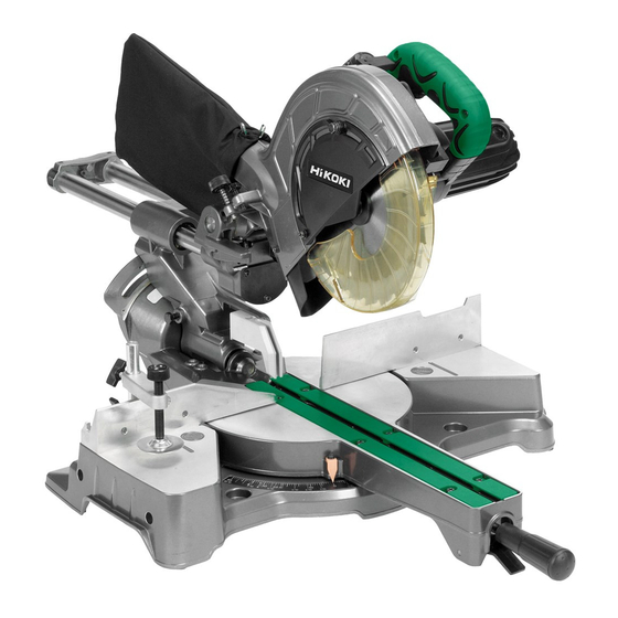
Slide compound miter saw
Hide thumbs
Also See for C 8FSHE:
- Handling instructions manual (176 pages) ,
- Handling instructions manual (72 pages) ,
- Handling instructions manual (94 pages)

Subscribe to Our Youtube Channel
Related Manuals for HIKOKI C 8FSHE


Summary of Contents for HIKOKI C 8FSHE
- Page 1 滑动复合式斜口锯 Slide Compound Miter Saw C 8FSHE C 8FSE • 保留备用 Keep for future reference 使用说明书 Handling instructions...
-
Page 2: Table Of Contents
中文 目次 作业上的一般注意事项.......2 打开包装.............7 使用复合式斜口锯须知.......3 作业之前.............7 符号...............5 使用前调节电动工具........8 部件名称.............5 实际应用.............9 规格...............6 锯条的安装和拆卸........18 标准附件.............7 维护和检查.............19 选购件 (另售) ...........7 维修零部件一览表........22 用途...............7 作业上的一般注意事项 警告! 当使用电动工具时,为了减少造成火灾、电击和人身伤害,必须时刻遵守基本 注意事项,以及下述操作注意事项。 在操作本机之前,请通读本说明书,并予以妥善保管。 安全操作注意事项∶ 1. 工作场所应打扫干净,清理妥当,杂乱无章将导致事故。 2. 确保妥适的作业环境。电动工具不可任其风吹雨打。不得在潮湿的地方作业。 工作场所需保持充分的亮度。 请勿在有可能造成火灾或爆炸的地方使用电动工具。 3. 谨防触电事故。应避免身体同大地或接地表面接触不可让访客触摸电动工具 或延伸线缆 (例如∶管道、散热器、炉灶、冰箱等)。 4. 不可让孩童和体弱人士靠近工作场所。请勿让访客触摸工具或延伸线缆。与 作业无关的访客也必须保持安全距离。 5. 不使用的电动工具应存放到干燥而孩童和体弱人士伸手不及的高处,并加锁 保管。... -
Page 3: 使用复合式斜口锯须知
中文 12. 作业以安全第一为原则。工件要用夹具或台钳卡紧。这样做,比用手按压更 为可靠,也能够让双手专心操作。 13. 作业时脚步要站稳,身体姿势要保持平衡。 14. 工具应维护妥善,经常保持锋利、清洁才能充分发挥性能,落实作业安全的 要求。应按规定加注润滑脂、更换附件。线缆应定期检查,如发现损伤应即 委托专业性的服务单位加以修复。延伸电缆如有损伤应予更换。手柄要保持 干燥,并防止沾附油脂类。 15. 不使用时、维修前以及更换附件 (如∶刀具、钻头、锯具等) 之前,都必须 拆卸电源插头才行。 16. 开动前务必把调整用键和扳手类拆除下来。这一点与安全有关。应养成习惯, 严格遵守。 17. 谨防误开动。插头一插上电源插座,指头就不可随便接触电源开关。插接电 源之前,应先确认∶开关是否切断。 18. 室外延伸线缆的使用。室外作业时,必须使用专用的延伸线缆。 19. 保持高度警觉,充分掌握情况,以正常的判断力从事作业。疲惫时切不可开 动电动工具。 20. 检查损坏部件。在继续使用电动工具之前,应详细检查各部零件以及防护装 置有无损坏,以便判断工具能否正常工作、能否发挥正常效能。检查转动部 份的对准、空转、各零件有无异常、安装是否妥善以及其它足以给工作带来 不良影响的情况。如防护以及其它零件损伤了。除非本说明书中已有记载否 则应即委托服务中心进行妥善修理或更换。开关一发现缺陷,应即委托服务 中心加以更换。如开关不能正常地接通或切断,绝不可使用该电动工具。 21. 警告 使用非本说明书中的推荐的附件可能有发生人身损害的危险。 22. 本工具必须委托有资格的维修人员进行维修。 本电动工具满足相关的安全要求。 维修必须由专业人员使用纯正配件来进行。 否则有可能会给用户造成人身损害。... - Page 4 中文 8. 不可使用溶剂擦拭塑料零件。因为∶汽油、冲淡剂、轻质汽油、四氯化碳、 酒精等都会使塑料损伤或发生龟裂,所以应避免使用。擦拭塑料制品,可以 使用稍微沾湿了肥皂水的柔布。 9. 只能使用HiKOKI指定的更换零件。 10. 本电动工具只在更换炭刷时才可拆解。 11. 本使用说明书中的组装分解图仅用于经授权的维修店。 12. 切勿切割铁金属或砖瓦材料。 13. 提供充足的总体或局部照明。原料与成品工件应位于操作员的正常工作位置 附近。 14. 必要时应使用适当的个人保护设备,可包括 : 听力保护,以减少听力受损的风险。 眼部保护,以减少眼睛受伤的风险。 呼吸保护,以减少吸入有害灰尘的风险。 手套,用于操作锯条 (移动锯条时应尽可能把锯条放在支架中) 以及粗糙材料。 15. 操作员应接受机器使用、调节与操作方面的充分培训。 16. 在机器运行且锯头未处于停止位置时,不得从切割区域移去工件的任何切片 或其他部分。 17. 复合式斜口锯的下护罩锁定在开启位置时,切勿使用复合式斜口锯。 18. 确保下护罩能够平滑地移动。 19. 安全罩未处于正常位置时请勿使用复合式斜口锯,要在其工作状态良好且得 到正确的维护的情况下使用。 20. 使用经过正确磨快的锯条。注意锯条上标注的最大速度。 21. 锯条破损或变形时请勿使用。...
-
Page 5: 部件名称
中文 39. 在进行切割作业时,操作员务必将锯片朝外推。 40. 务必考虑切割操作中所有可能产生的遗留风险,如激光辐射对眼睛的伤害、 无意中接触机器滑动机械部分的运动部件等等。 符号 警告! 如下所示的符号用于本机。使用前请务必理解其含意。 为降低伤害风险,用户必须阅读使用说明书 部件名称 手柄 齿轮箱 电动头 垫圈 (D) 主轴盖 灯 (仅 C8FSHE) 防尘袋 回转支架 电动机 锯片 支架 (A) 下护罩 激光标记器 挡板 (A) (仅 C8FSHE) 指针 (用于斜接尺) 导板 虎钳组件 回转台 挡板 (B) 连杆 侧手柄... - Page 6 中文 规格 65 mm×312 mm 0° **75 mm×262 mm 连同辅助板 (30 mm) 65 mm×220 mm 斜接 45° **75 mm×185 mm 连同辅助板 (20 mm) 45 mm×312 mm 左 45° **50 mm×252 mm 连同辅助板 (30 mm) 最大切割容量 斜角 高 × 宽 60 mm×312 mm 右...
-
Page 7: 标准附件
中文 标准附件 除了主机 (1 台) 外,产品包中还包括表中所列的附件。 216 mm TCT 锯条 (安装在工具上) 防尘袋 10 mm 套筒扳手 虎钳组件 支架 侧手柄 选购件 (另售) (1) 扩展支架和止动片 (2) 锯片 216 mm TCT 锯片 (总齿数:60) (3) 冠状模塑虎钳组件 (包括冠状模塑止动片 (L)) (4) 冠状模塑止动片 (L) (5) 冠状模塑止动片 (R) (6) 小挡板 用途... -
Page 8: 使用前调节电动工具
中文 2. 电源开关 确认电源开关是否切断。若电源开关接通,则插头插入电源插座时电动工具 将出其不意地立刻转动,从而招致严重事故。 3. 延伸线缆 若作业场所移到离开电源的地点,应使用容量足够、铠装合适的延伸线缆, 并且要尽可能地短些。 4. 当准备运输电动工具时,其主要部件须用锁 定插销固定 手柄 稍稍移动手柄,可使锁定插销脱落。 在运输过程中,将锁定插销锁在齿轮箱内 (图 3)。 5. 将防尘袋安装在电动工具上 (第 5 页的图 1) 插销 6. 安装 图 3 保证机器始终固定在工作台上。 请将电动工具安装在水平的工作台上。 选择长度适合工作台厚度的 8 mm 直径螺栓。 螺栓长度至少为 25 mm 加工作台厚度。 例如,在 25 mm 厚度工作台上使用 8 mm×65 mm 螺栓。 使用前调节电动工具... -
Page 9: 实际应用
中文 2. 检查锯片的下限位置 (图 5 与图 6) 8 mm 深度 齿轮箱 检查锯片是否可以降低到导板以 调节螺栓 下 10 mm 至 11 mm。更换新锯片 回转支架 锯片 时,请按照锯片不会切割到回转台 或无法进行完整切割的原则调节 下限位置。 回转台 如需调节锯片的下限位置,请遵 图 5 循下列第 (1) 步。(图 6) 此外,改变用作锯片下限位置止 动片的 8 mm 深度调节螺栓的位置 8 mm 深度 时。... - Page 10 中文 2. 开关操作 拉动触发器打开开关。松开触发器便可 关闭开关。 3. 调整底座支架 (图 8) 6 mm 螺栓 用随附的 10 mm 套筒扳手拧松 6 mm 螺 支架 栓。调整底座支架,使其底面接触到工 作台或地面。 图 8 调整完毕后,用 6 mm 螺栓紧紧固定。 螺栓支架 4. 使用虎钳组件 (标准附件) (图 9) 旋钮 6 mm 翼栓 (B) (1) 可拧松 6 mm 翼栓 (A),将虎钳组件安装 在左挡板...
- Page 11 中文 6. 确认使用小挡板 (选购附件) 在直接角度切割和右斜角切割中, 请使用小挡板。这样就可以进行左 斜角切割、右斜角切割和直接角度 副挡板 切割,实现对具有宽大背面的材料 进行稳定的切割。 警告! 挡板 (B) 在左斜角切割中,请逆时针旋转小 图 10 挡板 (图 10)。如果不是逆时针旋 转,主机或锯片可能与小挡板接触,从而引起伤害。 7. 使用墨线 在降低电动机部分时,下护罩升起,而出现锯条。 将墨线与锯条对齐。 注意! 在锯条旋转时切勿提起下护罩。 不仅会接触副挡板并影响切割精度,还可能损坏安全罩。 开关 8. 安装侧手柄 (第 5 页的图 1) 安装本机器随附的侧手柄。 (用于激光标记器) (仅 C8FSHE) 9. 激光线的位置调节 (仅适于 C8FSHE 型号) 可以方便地在本工具上画墨线以进...
- Page 12 中文 (2) 然后转动调节器并移动激光线。(如 虎钳组件 果顺时针转动调节器,则激光线 将向右移动;如果逆时针转动调节 器,则激光线向左移动。 ) 如使用时 墨线与锯条的左侧对齐,则将激光 激光线 线与凹槽的左端对齐 (图 12)。如墨 线与锯条的右侧对齐,则将激光线 凹槽 调节器 与凹槽的右侧对齐。 (用于激光标记器) (3) 调节激光线的位置之后,在工件上 (仅 C8FSHE) 画出一条直角墨线,并将墨线与激 图 12 光线对齐。对齐墨线时,应一点一 点地滑动工件,并在激光线与墨线 重叠的位置将其用虎钳固定。再次进行凹槽操作,并检查激光线的位置。如 需改变激光线的位置,则按照第 (1) 至 (3) 步再次进行调节。 警告! ○ 在将电源插头插入插座之前,确保主体与激光标记器均关闭。 ○ 在使用开关调节激光线的位置时应极为小心,因为操作时电源插头已插入插 座。 如在无意中拉动了开关,则锯条会旋转,并造成事故。...
- Page 13 中文 注 : ○ 将墨线与激光线重叠以进行切割。 ○ 当墨线与激光线重叠时,光的强弱会发生变化,使切割操作稳定。因为这样 可以方便地分辨线的一致性。这确保了最小的切割误差。 ○ 在室外或靠近窗户的操作中,可能由于日光的原因而难以看清激光线。此时 应移至不直接暴露于日光的地点,并进行操作。 ○ 不要拖动电动头后方的电线或用手指、木头等 钩住,否则电线可能脱落,使激光标记器不能 点亮。 激光线 ○ 定期检查并确认激光线的位置是否正确。检查 方法:在工件上画出一条直角墨线,其高度约 20 mm、宽度约 89 mm,并检查激光线是否与 标志 墨线对齐 [墨线与激光线之间的偏离应小于墨线 (预先标记) 的宽度(0.5 mm)] (图 14)。 图 14 10. 切割操作 (1) 如图 15所示,锯条的宽 度为切割宽度。因此,在 需要长度 时将工件向...
- Page 14 中文 11. 切割窄工件 (按压切割) 将回转支架向下滑动至支架 (A),然后旋紧滑动固定旋钮 (第 5 页的图 2)。 降低手柄来切割工件。以该方式使用电动工具允许切割最大 65 mm 的工 件。 6 mm 平头螺丝 辅助板 12. 切割大工件 根据工件高度的不同,可能会出现 6 mm 螺母 无法进行完整切割的情况。此时, 借助挡板面上的 7 mm 孔 (每侧各 挡板 有两个孔),使用 6 mm 平头螺丝和 6 mm 螺母安装辅助板。(图 16) 关于辅助板厚度,参见“规格”...
- Page 15 中文 15. 斜角切割步骤 (图 18) 支架 (A) 注意! 固定销 ○ 斜角切割时,确保夹紧杆固定牢固。 指针 ○ 当 要 切 除 的 材 料 长 度 超 过 25 mm 夹紧杆 (用于斜角尺) 时,请执行此操作。有时会因锯片 卡在下护罩内而无法完成切割。 角尺 图 18 (1) 松开夹紧杆并使锯片向左或向右倾斜。 将电动头向右倾斜时,向右拉动固定销。 注 : 松开夹紧杆,向左倾斜电动工具,然后拉动固定销,进行 48 度的切割。 松开夹紧杆,向左倾斜的同时将固定销插入电动工具。此时,固定销将插入...
- Page 16 中文 17. 切割长材料 切割长材料时,请使用与支架 (选购附件) 和特别辅助设备底座等高的辅助 平台。 最大尺寸: 木材 (宽×高×长) 300 mm×45 mm×1050 mm,或 180 mm×25 mm×1600 mm 18. 安装支架 (选购件) 6 mm 旋钮螺栓 在切割操作中,支架可用于延 (选购件) 长工件台并使之保持正确位置。 支架 (1) 如 图 19 所 示, 使 用 方 钢 来 对 (选购件) 方钢...
- Page 17 中文 (2) 冠状模塑虎钳(B) (选购件) 可安 冠状模塑虎钳组件 装在左挡板 (挡板 (B)) 或右挡板 (选购件) 6 mm 翼栓 (B) (挡板(A)) 上。它可与冠状模塑 旋钮 的斜角结合,并可按下虎钳。 然 后 按 照 需 要 转 动 上 部 旋 钮, 以可靠地连接冠状模塑。如需 挡板 升高或降低虎钳组件,首先应 松开 6 mm 翼栓。 6 mm 翼栓 (A) 冠状模塑...
-
Page 18: 锯条的安装和拆卸
中文 22. 使用灯 (仅 C8FSHE 型号) 警告! ○ 将电源线插入电源插座之前,请检查确认电动工具和灯的电源关闭。 ○ 使用期间及稍后,灯的温度很高,任何情况下均不得触碰。 否则可能导致烧伤。 注意! ○ 切勿让灯受到重力撞击。 否则可能导致灯的损坏或寿命缩短。 ○ 仅在切割时才能将灯打开。 ○ 请勿持续让灯光照射到眼睛。 否则可能导致眼睛损伤。 ○ 用软布轻轻擦去粘附在照明透镜上的所有灰尘,切勿刮伤或损坏灯。 刮伤照明透镜可能导致照明减弱。 ○ 灯的开关装有防尘罩。确保开关罩不会被刮伤或损坏。 ○ 有时会出现锯屑进入开关,导致 开关(用于灯) 灯的故障。 (仅 C8FSHE) 灯 (1) 将电动工具的插头插入电源插座。 (2) 将灯开关拨到上位 (ON) 使其点 亮,拨到下位 (OFF) 使其熄灭 (图... -
Page 19: 维护和检查
中文 注 : 10 mm 主轴锁 如难以按下主轴锁以锁定主轴,则在于 套筒扳手 主轴锁上施加压力的同时用 10 mm 套筒 扳手转动螺栓。 向内按下主轴锁时,锯片主轴被锁定。 (3) 取下螺栓与垫圈 (D)。 (4) 提起下护罩并安装锯片。 垫圈 (D) 螺栓 警告! 下护罩 安装锯片时,确认锯片上的旋转指针标 图 27 志与齿轮箱的转动方向一致。 圈 锯片 (5) 仔细清洗垫圈 (D) 和螺栓,并将其安装 螺栓 在锯片主轴上。 (6) 按下主轴锁,然后用 10 mm 套筒扳手将 螺栓向左转动以旋紧。... - Page 20 中文 1. 检查锯条 发现变质或损坏后应立即更换锯条。 损坏的锯条可引起人身伤害,而磨损的锯条则可导致无效的操作,并可能使 电动机过载。 注意! 切勿使用不锋利的锯条。锯条不锋利时,它对于由工具手柄所施加的手部压 力的阻力会增加,使电动工具的使用变得不安全。 2. 检查安装螺丝 要经常检查安装螺丝是否紧固妥善。若发现螺丝松了,应立即重新扭紧,否 则会导致严重的事故。 3. 检查炭刷 (图 29) 磨损极限线 马达使用炭刷,它是消耗部品,因此使用过久的 炭刷将会导致马达故障,用具有相同炭刷号的新 炭刷去更换旧的,炭刷编号用数字表示炭刷何时 5 mm 用旧或接近于磨损极限。此外,要经常保持炭刷 12 mm 清洁以及保证它在刷握里能自由滑动。 图 29 4. 更换炭刷 用无头螺丝刀卸下炭刷盖、然后可以很容易的取下炭刷。 5. 电动机的维护 电动机绕线是电动工具的“心脏部分” 。应仔细检查有无损伤,是否被油液 或水沾湿。 6. 检查下护罩是否操作无误 在每次使用工具之前,测试下护罩 (见第 8 页的图 4) 以确保其状态良好且运 动自如。...
- Page 21 中文 9. 清洁 定期用蘸有肥皂水的湿布除去电动工具表面上的碎屑和其它废料。为了避免 电动机发生故障,切勿使其接触油或水。 (仅适于 C8FSHE 型号) 如由于碎屑等粘在激光标记器发光部分的窗口上而无法看清激光线,则用干 布或以肥皂水等蘸湿的软布擦拭并清洁窗口。 10. 维修零部件一览表 注意! HiKOKI牌电动工具的维修、改造和检查须由经HiKOKI公司授权的维修中心 进行。 当要求维修或其它保养服务时,若将此零部件一览表与电动工具一起呈交给 经HiKOKI公司授权的维修中心,将有助于维修或保养工作。 在操作和维修电动工具时,必须遵守贵国制定的安全的有关规则和标准。...
-
Page 22: 维修零部件一览表
中文 维修零部件一览表 C8FSHE 606 611 607 620 621 626 52 53... - Page 23 中文 C8FSHE 120 121...
- Page 24 中文 C8FSHE 169 170 224 201 200...
- Page 25 中文 项目 项目 零件名称 数量 零件名称 数量 号 号 止推垫圈 机用螺丝 (附垫圈) M4×12 销盖 夹紧杆 旋钮螺栓 M10×66 螺栓 (左手) D10 翼栓 M6×15 专用垫圈 螺丝固定器 固定销 螺栓垫圈 M6 O 型环 (1AP-12) 虎钳轴 机用螺丝 M4×8 虎钳板 螺栓垫圈 M4 机用螺丝 M4×10 回转支架轴 (A) 虎钳组件...
- Page 26 中文 项目 项目 零件名称 数量 零件名称 数量 号 号 连接片 自攻螺丝 (附法兰) D5×25 回转支架轴 (A) 123 尼龙锁紧螺栓 (A) M8×25 2 底座橡胶 124 固定器 (A) O 型环 (P-6) 125 下部罩组件 止动销组件 自攻螺丝 (附法兰) 离合器螺丝 D4×16 离合器弹簧 152 线保护壳 D10.1 调整垫圈 (B) T0.5 153 线夹...
- Page 27 中文 项目 项目 零件名称 数量 零件名称 数量 号 号 181 定子组件 216 复位弹簧 182 滚珠轴承 608VVC2PS2L 217 主轴组件 183 尘封 218 滚珠轴承 6003VVCM 184 滚珠轴承 6000VVCMPS2L 219 轴承固定器 185 轴承衬套 220 滚珠轴承 608VVC2PS2L 186 橡胶衬套 221 垫圈 (D) 187 电枢组件 222 机用螺丝...
- Page 28 中文 项目 零件名称 数量 号 622 冠状模塑止动片固定器 623 冠状模塑止动片 (右) 624 翼栓 M6×15 冠状模塑止动片 (右) 组件 626 固定器组件 627 固定器 628 翼状螺母 M6 629 螺母 M6 630 垫圈 (H) 631 虎钳板 632 高抗拉螺栓 M6×25 633 导架组件...
- Page 29 中文 C8FSE 606 611 607 620 621 626 51 52...
- Page 30 中文 C8FSE 98 92 105 106...
- Page 31 中文 C8FSE 208 210 216 195 194...
- Page 32 中文 项目 项目 零件名称 数量 零件名称 数量 号 号 销盖 机用螺丝 (附垫圈) M4×12 旋钮螺栓 M10×66 夹紧杆 翼栓 M6×15 螺栓 (左手) D10 螺丝固定器 专用垫圈 螺栓垫圈 M6 固定销 虎钳轴 O 型环 (1AP-12) 虎钳板 机用螺丝 M4×8 机用螺丝 M4×10 螺栓垫圈 M4 虎钳组件 回转支架轴 (A) 螺栓...
- Page 33 中文 项目 项目 零件名称 数量 零件名称 数量 号 号 螺栓垫圈 M4 自攻螺丝 (附法兰) D4×20 机用螺丝 M4×8 162 手柄盖 电线 165 内部电线 (G) 机用螺丝 (附垫圈) M4×12 166 开关 尼龙夹 167 柱式终端 (A) 支架 169 盖 机用螺丝 M4×8 170 弹簧 滚珠衬套 171 锁固杆 100 衬套...
- Page 34 中文 项目 项目 零件名称 数量 零件名称 数量 号 号 200 防尘导架 614 垫圈 (H) 201 导架固定器 615 底座橡胶 螺栓 (左手) 附垫圈 机用螺丝 (附垫圈) M7×17.5 M4×10 203 TCT 锯片 617 虎钳轴 204 圈 618 旋钮螺栓 M10×54 205 平头螺丝 M4×10 619 冠状模塑虎钳组件 206 盖...
-
Page 35: General Operational Precautions
English CONTENTS GENERAL OPERATIONAL PRECAUTIONS ..........35 PRECAUTIONS ON USING COMPOUND MITER SAW ......37 SYMBOL ....................... 38 NAME OF PARTS..................39 SPECIFICATIONS ..................40 STANDARD ACCESSORIES ............... 41 OPTIONAL ACCESSORIES (sold separately)..........41 APPLICATION ....................41 UNPACKING ....................41 PRIOR TO OPERATION ................ - Page 36 English 10. Connect dust extraction equipment. Cutting operation by this compound miter saw may produce considerable amount of dust from extraction duct on fi xed guard. (Dust material: Wood or Aluminium) If devices are provided for the connection of dust extraction and collection facilities ensure these are connected and properly used.
-
Page 37: Precautions On Using Compound Miter Saw
Clean plastic parts with a soft cloth lightly dampened with soapy water. Use only original HiKOKI replacement parts. 10. This tool should only be disassembled for replacement of carbon brushes. 11. The exploded assembly drawing on this handling instructions should be used only for authorized service facility. -
Page 38: Symbol
English 22. Do not use saw blades manufactured from high speed steel. 23. Use only saw blades recommended by HiKOKI. 24. The saw blades should be 216 mm external diameter. 25. Select the correct saw blade for the material to be cut. -
Page 39: Name Of Parts
English NAME OF PARTS Motor Handle Gear Case Head Washer (D) Spindle Cover Light (Only C8FSHE) Dust Bag Hinge Motor Saw Blade Holder (A) Lower Guard Laser Marker Fence (A) (Only C8FSHE) Indicator (For miter scale) Table Insert Vise Assembly Turntable Fence (B) Lever... -
Page 40: Specifications
English SPECIFICATIONS 65 mm × 312 mm 0° **75 mm × 262 mm with aux. board (30 mm) 65 mm × 220 mm Miter 45° **75 mm × 185 mm with aux. board (20 mm) 45 mm × 312 mm Left 45°... -
Page 41: Standard Accessories
English STANDARD ACCESSORIES In addition to the main unit (1 unit), the package contains the accessories listed in the below. 216 mm TCT Saw blade (mounted on tool) Dust bag 10 mm Box wrench Vise Assembly Holder Side handle OPTIONAL ACCESSORIES (sold separately) Extension Holder and Stopper Saw blade 216 mm TCT Saw blade (Total teeth: 60) Crown molding Vise Ass’y (Include Crown molding Stopper (L)) -
Page 42: Adjusting The Power Tool Prior To Use
English Extension cord When the work area is removed from the power Handle source, use an extension cord of suffi cient thickness and rated capacity. The extension cord should be kept as short as practicable. When the power tool is prepared for shipping, its main parts are secured by a locking pin Locking Pin Move the handle slightly so that the locking pin can... -
Page 43: Practical Applications
English To adjust the lower limit position of the saw blade, follow the procedure (1) 8 mm Depth indicated below. (Fig. 6) Adjustment Bolt Furthermore, when changing the Hinge position of a 8 mm depth adjustment Gear Case bolt that serves as a lower limit position stopper of the saw blade. - Page 44 English Base holder adjustment (Fig. 8) Loosen the 6 mm bolt with the supplied 10 mm box wrench. Adjust the base holder until its bottom surface contacts the bench or the fl oor 6 mm Bolt surface. After adjustment, fi rmly tighten the 6 mm bolt. Holder Using the Vise Assembly (Standard accessory) (Fig.
- Page 45 English CAUTION After adjusting the table insert for right angle cutting, the table insert will be cut to some extent if it is used for bevel angle cutting. When bevel cutting operation is required, adjust the table insert for bevel angle cutting.
- Page 46 English Then, turn the adjuster and shift the laser Vise Assembly line. (If you turn the adjuster clockwise, the laser line will shift to the right and if you turn it counterclockwise, the laser line will shift to the left.) When you work with the ink line aligned with the left side of the saw blade, Laser line align the laser line with the left end of the...
- Page 47 English Use of controls or adjustments or performance of procedures other than those ○ specifi ed herein may result in hazardous radiation exposure. NOTE Perform cutting by overlapping the ink line with the laser line. ○ When the ink line and the laser line are overlapped, the strength and weakness of light ○...
- Page 48 English CAUTION For maximum dimensions for cutting, refer to “SPECIFICATIONS” table. ○ Increased pressure on the handle will not increase the cutting speed. On the ○ contrary, too much pressure may result in overload of the motor and/or decreased cutting effi ciency. Confi...
- Page 49 English 14. Miter cutting procedures Indicator (For miter scale) Loosen the side handle and pull up the lever for angle stoppers. Then, adjust the turntable until the Side Handle Miter indicator aligns with desired setting Scale on the miter scale (Fig. 17). Re-tighten the side handle to secure the turntable in the desired position.
- Page 50 English Adjust the bevel angle to the desired setting while watching the bevel angle scale and indicator, then secure the clamp lever. WARNING When the workpiece is secured on the left or right side of the blade, the short cut- ○...
- Page 51 English After adjustment, fi rmly tighten the wing nut and fasten the holder with the 6 mm knob bolt (optional accessory). If the length of Height Adjustment Bolt 6 mm is insuffi cient, spread a thin plate beneath. Make sure the end of Height Adjustment Bolt 6 mm does not protrude from the holder.
- Page 52 English The crown molding vise (B) (Optional Crown molding Vise Ass’y accessory) can be mounted on either (Optional accessory) the left fence (Fence (B)) or the right 6 mm Wing Bolt (B) fence (Fence (A)). lt can unite with the Knob slope of the crown molding and vice can be pressed down.
-
Page 53: Mounting And Dismounting Saw Blade
English NOTE When cutting a single groove at either end of the workpiece, remove the unneeded portion with a chisel. 22. Using the Light (Only Model C8FSHE) WARNING Check to ascertain that the main unit and light are off before plugging the cord into ○... - Page 54 English Mounting the saw blade (Fig. 26, Fig. 27 and Fig. 28) Spindle Lock Use the accessory 10 mm box wrench to loosen the 6 mm bolt fastening the spindle cover and then rotate the spindle cover. Press in spindle lock and loosen bolt with 10 mm box wrench.
-
Page 55: Maintenance And Inspection
English CAUTION Never attempt to install saw blades except 216 mm in diameter. MAINTENANCE AND INSPECTION WARNING To avoid an accident or personal injury, always confi rm the trigger switch is turned OFF and that the power plug has been disconnected from the receptacle before performing any maintenance or inspection of this tool. - Page 56 Always assign the repair of laser device to HiKOKI Authorised Service Center. This Parts List will be helpful if presented with the tool to the HiKOKI Authorized Service Center when requesting repair or other maintenance. In the operation and maintenance of power tools, the safety regulations and...
-
Page 57: Service Parts List
English SERVICE PARTS LIST C8FSHE 606 611 607 620 621 626 52 53... - Page 58 English C8FSHE 120 121...
- Page 59 English C8FSHE 169 170 224 201 200...
- Page 60 English Item Item Part Name Q’TY Part Name Q’TY MACHINE SCREW 37 SCREW HOLDER (W/WASHERS) M4×12 38 BOLT WASHER M6 CLAMP LEVER 39 VISE SHAFT BOLT (LEFT HAND) D10 40 VISE PLATE SPECIAL WASHER 41 MACHINE SCREW M4×10 SET PIN 42 VISE ASS’Y O-RING (1AP-12) 43 BOLT M8×35...
- Page 61 English Item Item Part Name Q’TY Part Name Q’TY ADJUSTING WASHER (B) 155 HOUSING ASS’Y T0.5 156 NAME PLATE 99 PLATE (B) MACHINE SCREW 100 SPRING (W/WASHERS) M5×40 101 CLUTCH SPRING HEX. SOCKET SET SCREW M5×8 102 SPRING 159 BRUSH HOLDER SEAL LOCK HEX.
- Page 62 English Item Item Part Name Q’TY Part Name Q’TY 189 LOCK SPRING 501 BOX WRENCH 10MM 190 NYLOCK BOLT M8×25 502 DUST BAG MACHINE SCREW 601 NYLON NUT M6 (W/WASHERS) M5×8 602 PLATE 192 SPINDLE COVER 603 SUB FENCE MACHINE SCREW 604 FLAT SCREW M6×25 (W/WASHERS) M4×12 605 SUB FENCE ASS’Y...
- Page 63 English Item Part Name Q’TY 630 WASHER (H) 631 VISE PLATE 632 HIGH TENSION BOLT M6×25 633 GUIDE ASS’Y...
- Page 64 English C8FSE 606 611 607 620 621 626 51 52...
- Page 65 English C8FSE 98 92 105 106...
- Page 66 English C8FSE 208 210 216 195 194...
- Page 67 English Item Item Part Name Q’TY Part Name Q’TY 37 BOLT WASHER M6 MACHINE SCREW (W/WASHERS) M4×12 38 VISE SHAFT CLAMP LEVER 39 VISE PLATE BOLT (LEFT HAND) D10 40 MACHINE SCREW M4×10 SPECIAL WASHER 41 VISE ASS’Y SET PIN 42 BOLT M8×35 O-RING (1AP-12) 43 SPRING WASHER M8...
- Page 68 English Item Item Part Name Q’TY Part Name Q’TY 99 BALL BUSHING HEX. HD. TAPPING SCREW D4×60 100 BUSHINGH 174 BRUSH TERMINAL 101 KNOB BOLT M6×25 175 STATOR ASS’Y 102 LOCK SPRING BALL BEARING SEAL LOCK HEX. SOCKET 608VVC2PS2L SET SCREW M6×10 177 DUST SEAL 104 MACHINE SCREW M4×12 BALL BEARING...
- Page 69 English Item Item Part Name Q’TY Part Name Q’TY 208 RETURN SPRING CROWN MOLDING STOPPER HOLDER 209 SPINDLE ASS’Y CROWN MOLDING 210 BALL BEARING 6003VVCM STOPPER (R) 211 BEARING HOLDER 624 WING BOLT M6×15 BALL BEARING CROWN MOLDING STOPPER 608VVC2PS2L (R) ASS’Y 213 WASHER (D) 626 HOLDER ASS’Y...
- Page 72 服务中心 工机商业(中国)有限公司 上海市闵行区浦江工业园区三鲁路3585号7幢3楼 制造商 福建高壹工机有限公司 福建省福州市福兴投资区湖塘路 编号:C99169324 F 发行日期:2018年6月 中国印刷...
Need help?
Do you have a question about the C 8FSHE and is the answer not in the manual?
Questions and answers