
Related Manuals for Vecow EMBC-7000


Summary of Contents for Vecow EMBC-7000
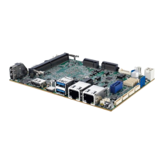
- Page 1 USER USER EMBC-7000 Manual Manual Intel ® Core™ Ultra 7 165U/5 135U SoC 3.5” Single Board Computer DDR5, 2.5G GigE LAN, USB Type-C, 4 COM, SUMIT B, TPM, Ignition Control 1.0.0 Edition 20241009...
-
Page 2: Record Of Revision
Record of Revision Version Date Remark Page Description 1.00 2024/10/09 Official Release ©Vecow EMBC-7000 User Manual... -
Page 3: Declaration Of Conformity
This manual is released by Vecow Co., Ltd. for reference purpose only. All product offerings and specifications are subject to change without prior notice. It does not represent commitment of Vecow Co., Ltd. Vecow shall not be liable for direct, indirect, special, incidental, or consequential damages arising out of the use of the product or documentation or any infringements upon the rights of third parties, which may result from such use. -
Page 4: Order Information
Order Information Part Number Description EMBC-7000 3.5" Embedded Single Board Computer, onboard ® Intel Core™ Ultra 7 165U Processor (Meteor Lake-U), DDR5 SO- EMBC-7000E-165U DIMM, 2.5GigE LAN, 1 USB 3.2 Gen 2x2 Type-C, 2 USB 3.2 Gen 2, 4 COM Header, 1 SATA, SUMIT B, 9V to 55V DC-in EMBC-7000 3.5"... -
Page 5: Optional Accessories
Certified DDR5 8GB 4800/5600MHz RAM 61-13Q1009-02A COM Port Cable 61-13I0707-0CA SATA Data Cable 61-13P0415-0CA SATA Power Cable 75-VE90003-S10 Heat Sink for EMBC-7000 Series 75- VE90003-P10 Heat Spreader for EMBC-7000 Series 61-13T10LM-3CG Audio Cable 61-193102U-156 USB 2.0 Cable ©Vecow EMBC-7000 User Manual... -
Page 6: Table Of Contents
1.4.4 Dimensions of Fan sink 1.4.5 Dimensions of MB+Heat Spreader 1.4.6 Dimensions of MB+Heat Sink 1.4.7 Dimensions of MB+Fan Sink CHAPTER 2 GETTING TO KNOW YOUR EMBC-7000 2.1 Packing List 2.2 Main Board Expansion Connectors 2.3 Main Board Jumper Settings 2.4 Ignition Control... - Page 7 4.6 Save & Exit APPENDIX A : GPIO GUIDE APPENDIX B : Software Functions APPENDIX C : RAID Functions APPENDIX D : Power Consumption APPENDIX E : Supported Memory & Storage List APPENDIX F : Supported SUMIT Card List ©Vecow EMBC-7000 User Manual...
-
Page 8: Chapter 1 General Introduction
CPU productivity by up to 14%. With a fanless design supporting an extended operating temperature range of -40°C to 75°C, DC 9V to 55V power input, and software ignition power control, the EMBC-7000 is well suited for factory automation, robotic SLAM, intelligent vending, smart retail, and other AIoT applications. -
Page 9: Features
• DC 9V to 55V Power Input, Software Ignition Power Control ® • Supports Intel vPro, TSN, TCC, and TPM 2.0 • Optional VHub One-Stop AIoT Solution Service supports OpenVINO™ toolkit for AI Computing ©Vecow EMBC-7000 User Manual GENERAL INTRODUCTION... -
Page 10: Product Specification
• 1 USB 3.2 Gen 2x2 Type-C Connector • 1 SIM Card Socket Front I/O • 1 Power Button • 1 Reset Button • 1 Power LED • 1 Wireless LED • 1 WiFi LED • 1 HDD LED ©Vecow EMBC-7000 User Manual GENERAL INTRODUCTION... - Page 11 351 g (0.77 lb) Environment Operating Temperature -40°C to 75°C (-40°F to 167°F) with airflow Storage Temperature -40°C to 85°C (-40°F to 185°F) Humidity 5% to 95% humidity, non-condensing Relative Humidity 95% at 75°C CE, FCC, ICES ©Vecow EMBC-7000 User Manual GENERAL INTRODUCTION...
-
Page 12: Specifications Of Embc-7000-165U
1.3.2 Specifications of EMBC-7000-165U System ® Processor Intel Core™ Ultra 7 165U Processor (Meteor Lake-U) ® Intel AI Boost Chipset Intel ® BIOS IT8786E • 1 DDR5 5600MHz Memory • Up to 48GB • 1 262-pin SO-DIMM Socket Graphics ®... - Page 13 351 g (0.77 lb) Environment Operating Temperature -40°C to 75°C (-40°F to 167°F) with airflow Storage Temperature -40°C to 85°C (-40°F to 185°F) Humidity 5% to 95% humidity, non-condensing Relative Humidity 95% at 75°C CE, FCC, ICES ©Vecow EMBC-7000 User Manual GENERAL INTRODUCTION...
-
Page 14: Specifications Of Embc-7000-135U
1.3.3 Specifications of EMBC-7000-135U System ® Processor Intel Core™ Ultra 5 135U Processor (Meteor Lake-U) ® Intel AI Boost Chipset Intel ® BIOS IT8786E • 1 DDR5 5600MHz Memory • Up to 48GB • 1 262-pin SO-DIMM Socket Graphics ®... - Page 15 351 g (0.77 lb) Environment Operating Temperature -40°C to 75°C (-40°F to 167°F) with airflow Storage Temperature -40°C to 85°C (-40°F to 185°F) Humidity 5% to 95% humidity, non-condensing Relative Humidity 95% at 75°C CE, FCC, ICES ©Vecow EMBC-7000 User Manual GENERAL INTRODUCTION...
-
Page 16: Mechanical Dimension
1.4 Mechanical Dimension 1.4.1 Dimensions of EMBC-7000 Unit : mm (inch) 146.0 (5.75) 50.0 (2) 85.7 (3.38) 5.1 (0.20) 55.2 (2.17) 85.7 (3.38) 1.4.2 Dimensions of Heat Spreader Unit : mm (inch) 150.4 (5.92) 12.0 (0.5) 85.7 (3.38) 50.2 (1.98) ©Vecow EMBC-7000 User Manual... -
Page 17: Dimensions Of Heat Sink
1.4.3 Dimensions of Heat sink Unit : mm (inch) 150.4 (5.92) 24.5 (0.9) 85.7 (3.38) 50.2 (1.98) 1.4.4 Dimensions of Fan sink Unit : mm (inch) 150.4 (5.92) 29.0 (1.1) 85.7 (3.38) 50.2 (1.98) ©Vecow EMBC-7000 User Manual GENERAL INTRODUCTION... -
Page 18: Dimensions Of Mb+Heat Spreader
50.0 (2) 85.7 (3.38) 5.1 (0.20) 12.0 (0.5) 55.2 (2.17) 85.7 (3.38) 1.4.6 Dimensions of MB+Heat Sink Unit : mm (inch) 146.0 (5.75) 24.5 (0.9) 50.0 (2) 85.7 (3.38) 5.1 (0.20) 55.2 (2.17) 85.7 (3.38) ©Vecow EMBC-7000 User Manual GENERAL INTRODUCTION... -
Page 19: Dimensions Of Mb+Fan Sink
1.4.7 Dimensions of MB+Fan Sink Unit : mm (inch) 29.0 (1.1) 146.0 (5.75) 50.0 (2) 85.7 (3.38) 5.1 (0.20) 55.2 (2.17) 85.7 (3.38) ©Vecow EMBC-7000 User Manual GENERAL INTRODUCTION... -
Page 20: Chapter 2 Getting To Know Your Embc-7000
GETTING TO KNOW YOUR EMBC-7000 2.1 Packing List Item Description EMBC-7000 3.5 Embedded Single Board Computer Cable Kit • COM Port Cable • COM Screw#4-40, L=5mm • SATA Data Cable • SATA Power Cable • USB 2.0 Cable • USB Screw PH-M3, L=6mm •... -
Page 21: Main Board Expansion Connectors
2.2 Main Board Expansion Connectors 2.2.1 EMBC-7000 Main Board Top Side View SYS_FAN1 M2B_CN1 eDP1 DC_IN1 MCM_CN1 JCOM1 JCOM2 JCOM3 JCOM4 JUSBPWR1 JSEL_DIO JRESET JSTATUS M2B_SIM1 CN_HDMI1 CN_TypeC1 CN_USB3 LAN2 LAN1 2.2.2 EMBC-7000 Main Board Bottom Side View CPU1 M2B_LED1... - Page 22 The pinouts of Miscellaneous port are listed in following table : JPWBTN JHDD JRESET JSTATUS Group Pin No. Description JPWBTN FP_PWR_BTN_IN JRESET FP_RST_BTN_N PWR_LED_P JSTATUS PWR_LED_N HDD_LED_P JHDD HDD_LED_N ©Vecow EMBC-7000 User Manual GETTING TO KNOW YOUR EMBC-7000...
- Page 23 2.2.4 BAT : Battery The EMBC-7000’s real-time clock is powered by a lithium battery. It is equipped with Panasonic BR2032 190mAh lithium battery. It is recommended that you not replace the lithium battery on your own, but if the battery needs to be changed, please contact the Vecow RMA service team.
- Page 24 2.2.6 JUSB1 : Internal USB 2.0 Connector The EMBC-7000 main board provides maxima four expansion USB ports. The USB interface supports 480 Mbps transfer rate which comply with high speed USB specification Rev. 2.0. The USB interface is accessed through one 10-pin JST 1.0mm connector. You will need an adapter cable if you use a standard USB connector.
- Page 25 The pin assignments of M2E_CN1 are listed in the following table: Pin No. Signal Name Pin No. Signal Name 3.3V 3.3V RESERVED/REFCLKn1 RESERVED/REFCLKp1 RESERVED/PETn1 RESERVED/PETp1 ALERT# (O)(0/3.3V) 12C_CLK (I)(0/3.3V) RESERVED/PERn1 12C_DATA (I/O)(0/3.3V) RESERVED/PERp1 PEWAKE0# (I/O)(0/3.3V) PERST03# (I)(0/3.3V) CLKREQ0# (I/O)(0/3.3V) ©Vecow EMBC-7000 User Manual GETTING TO KNOW YOUR EMBC-7000...
- Page 26 Pin No. Signal Name REFCLKn0 REFCLKp0 PETn0 PETp0 PERn0 PERp0 Module Key Module Key Module Key Module Key Module Key Module Key Module Key Module Key LED# (O)(od) 3.3V USB_D- 3.3V USB_D+ ©Vecow EMBC-7000 User Manual GETTING TO KNOW YOUR EMBC-7000...
- Page 27 LTE/5G module, and NVMe SSD (BW: PCIex2) that types include 3042/3052. The pin assignments of M2B_CN1 are listed in the following table : Pin No. Signal Name Pin No. Signal Name Ground Ground 3.3V Ground 3.3V CONFIG_1 3.3V SIM DETECT ©Vecow EMBC-7000 User Manual GETTING TO KNOW YOUR EMBC-7000...
- Page 28 CLKREQ# PETp0 PERST# PETn0 Ground PERp0 PERn0 Ground PETp1/USB3.1-TX+ DEVSLP PETp1/USB3.1-TX- UIM-PWR Ground UIM-DATA PETp1/USB3.1-RX+ UIM-CLK PETp1/USB3.1-RX- UIM-RESET Ground Mechanical Key Ground USB- LED_1# USB+ W_DISABLE1 Ground FULL_CARD_PWR_OFF/ON Ground 3.3V 3.3V ©Vecow EMBC-7000 User Manual GETTING TO KNOW YOUR EMBC-7000...
- Page 29 The pin assignments of M2M_CN1 are listed in the following table: Pin No. Function Pin No. Function Ground Ground 3.3V Ground 3.3V PEDET 3.3V Ground Mechanical Key Ground REFCLKp REFCLKn PEWAKE# Ground CLKREQ# PETp0/SATA_A+ PERST# PETn0/SATA_A- ©Vecow EMBC-7000 User Manual GETTING TO KNOW YOUR EMBC-7000...
- Page 30 Ground PERp0/SATA_B- PERn0/SATA_B+ Ground PETp1 DEVSLP PETn1 Ground PERp1 PERn1 Ground PETp2 PETn2 Ground PERp2 PERn2 3.3V Ground 3.3V PETp3 3.3V PETn3 3.3V Ground LED1# PERp3 PERn3 Ground 3.3V Ground 3.3V ©Vecow EMBC-7000 User Manual GETTING TO KNOW YOUR EMBC-7000...
- Page 31 Serial RS-422 RS-485 Pin No. RS-232 Port (5-wire) (3-wire) GND_EARTH GND_EARTH GND_EARTH ----------- RXD- ----------- ----------- ----------- 1, 2 3, 4 RXD+ ----------- ----------- ----------- TXD+ DATA+ ----------- ----------- TXD- DATA- ©Vecow EMBC-7000 User Manual GETTING TO KNOW YOUR EMBC-7000...
- Page 32 There are 2 USB 3.2 Gen2 connections available supporting up to 10GB per second data rate in the top side of SPC-9000. They are also compliant with the requirements of SuperSpeed (SS), high speed (HS), full speed (FS) and low speed (LS). ©Vecow EMBC-7000 User Manual GETTING TO KNOW YOUR EMBC-7000...
- Page 33 2.2.13 LAN1_CON , LAN2_CON : LAN Connector LAN2 LAN1 There are two 8-pin RJ-45 jacks supporting 100/1000/2500 Mbps Ethernet connections in the top side of EMBC-7000. LAN1_CON and LAN2_CON is ® powered by Intel I226-IT Ethernet engine. Using suitable RJ-45 cable, you can connect SPC-9000 system to a computer or to any other devices with Ethernet connection, for example, a hub or a switch.
- Page 34 CON lightens in solid green when the cable is properly connected to a 1000 Mbps Ethernet network; the LED indicator on the Left top corner of LAN1_CON and LAN2_CON will keep twinkling/ off when Ethernet data packets are being transmitted/ received. ©Vecow EMBC-7000 User Manual GETTING TO KNOW YOUR EMBC-7000...
- Page 35 2.2.14 eDP1 : eDP connector eDP1 EMBC-7000 supports eDP display and up to 3840 x 2400 pixels resolution. The pin assignments of eDP are listed in the following table: Pin No. Definition Pin No. Definition EDP_VDD EDP_PANEL_z_TX0- EDP_VDD EDP_PANEL_z_TX0+ EDP_BKLT_EN...
- Page 36 2.2.15 CN_DP1, CN_HDMI1 : DP and HDMI Connectors EMBC-7000 support Display Ports and HDMI and up to 4096 x 2304 pixels resolution. CN_DP1 CN_HDMI1 2.2.16 DC_CN1 : DC Power input DC_CN1 EMBC-7000 supports 9V to 55V DC power input by wire-to-board connector in the top side.
- Page 37 2.2.17 SATA1 : SATA III Connector There is a high performance Serial ATA III (SATA III) on the EMBC-7000. They support higher storage capacity with less cabling effort and smaller required space. The pin assignments of SATA1 are listed in the following table: Pin No.
- Page 38 B_PER_N0 C_CLKP B_CLKP C_CLKN B_CLKN CPRSNT#/C_PE_CLKREQ# C_PET_P0 C_PER_P0 C_PET_N0 C_PER_N0 C_PET_P1 C_PER_P1 C_PET_N1 C_PER_N1 C_PET_P2 C_PER_P2 C_PET_N2 C_PER_N2 C_PET_P3 C_PER_P3 C_PET_N3 C_PER_N3 PERST# WAKE# Reserves Reserves Reserves +3.3V +3.3V +3.3V +5V_AUX ©Vecow EMBC-7000 User Manual GETTING TO KNOW YOUR EMBC-7000...
- Page 39 2.2.20 SYS_FAN1 SYS_FAN1 Fan power connector supports higher thermal requirements Pin No. Definition Pin No. Definition +12V (2.0A max) Fan speed sensor Fan PWM ©Vecow EMBC-7000 User Manual GETTING TO KNOW YOUR EMBC-7000...
- Page 40 SIO_GPI84 SIO_GPO74 SIO_GPI85 SIO_GPO75 SIO_GPI86 SIO_GPO76 SIO_GPI87 SIO_GPO77 +3.3V +3.3V 2.2.22 RST_SW1 : RESET Button RST_SW1 Pin assignment as the following table : Pin No. Definition Pin No. Definition FP_RST_BTN_N FP_RST_BTN_N ©Vecow EMBC-7000 User Manual GETTING TO KNOW YOUR EMBC-7000...
- Page 41 2.2.24 M2B_SIM1 : Nano SIM Card Socket for M.2 key B Slot M2B_SIM1 The Nano SIM card socket is support Push-Push type. Please make sure to unplug the system power before inserting the Nano SIM card. ©Vecow EMBC-7000 User Manual GETTING TO KNOW YOUR EMBC-7000...
-
Page 42: Main Board Jumper Settings
2.3 Main Board Jumper Settings 2.3.1 TOP View of EMBC-7000 Main Board with Jumper Location The figure below is the top view of the EMBC-7000 main board. It shows the location of the jumpers. JUSBPWR1 JINGMODE1 You may configure your card to match the needs of your application by setting jumpers. - Page 43 JP4 provides eDP voltage selection function, Closing Pin 1 and Pin 2 is for 3.3V eDP power input; closing Pin 2 and Pin 3 is for 5V eDP power input. Pin No. Definition +3.3V 2.3.3 JP2 : Clear CMOS Pin No. Definition Normal Clear CMOS ©Vecow EMBC-7000 User Manual GETTING TO KNOW YOUR EMBC-7000...
- Page 44 2.3.4 JUSBPWR1 : Power Selection for EXT and INT USB 3.2 Gen2 / USB 2.0 Ports JUSBPWR1 Pin No. Definition +5V Standby Power +5V System Power 2.3.5 JIGNMODE1 : IGN Mode JINGMODE1 Pin No. Definition H/W mode S/W mode (Default) ©Vecow EMBC-7000 User Manual GETTING TO KNOW YOUR EMBC-7000...
-
Page 45: Ignition Control
2.4.1 Adjust Ignition Control Modes EMBC-7000 series series provides 16 modes of different power on/off delay periods adjustable via SW1 switch. The default rotary switch is set to 0 in ATX/AT power mode. - Page 46 5 seconds 30 minutes 5 seconds 1 hour 10 seconds 2 hours 10 seconds 4 hours 10 seconds 6 hours 10 seconds 8 hours 10 seconds 12 hours 10 seconds 24 hours ©Vecow EMBC-7000 User Manual GETTING TO KNOW YOUR EMBC-7000...
- Page 47 Note : 1. DC power source and IGN share the same ground. 2. EMBC-7000 supports 9V to 55V wide range DC power input in ATX/AT mode. In Ignition mode, the input voltage is fixed to 12V/24V for car battery scenario.
-
Page 48: Chapter 3 System Setup
3.1 Installing Heat Spreader / Heat Sink Step 1 The motherboard and Sink assembly before, thermal paste needs to be applied to the CPU. Step 2 Apply an amount of thermal paste about the size of three peas. ©Vecow EMBC-7000 User Manual SYSTEM SETUP... - Page 49 Step 3 Tear off the thermal pad film. Step 4 Place the motherboard and heat spreader in position. Fasten five PH-M3x4L screws. ©Vecow EMBC-7000 User Manual SYSTEM SETUP...
-
Page 50: Installing Fan Sink
Step 1 The motherboard and Sink assembly before, thermal paste needs to be applied to the CPU. Step 2 Apply an amount of thermal paste about the size of three peas. Step 3 Tear off the thermal pad film. ©Vecow EMBC-7000 User Manual SYSTEM SETUP... - Page 51 Step 4 Straighten out the fan wires. Step 5 Place the motherboard and fan sink in position. Fasten five PH-M3x4L screws. Step 6 Plug in the fan slot. ©Vecow EMBC-7000 User Manual SYSTEM SETUP...
-
Page 52: Installing Ddr5 So-Dimm Modules
3.3 Installing DDR5 SO-DIMM Modules Step 1 Find DDR5 SO-DIMM socket. Step 2 Install DDR5 RAM module into SO-DIMM slot. Step 3 Make sure the RAM module is locked by the memory slot. ©Vecow EMBC-7000 User Manual SYSTEM SETUP... -
Page 53: Installing Nano Sim Card
3.4 Installing Nano SIM Card Step 1 Install SIM card into the SIM card slot. ©Vecow EMBC-7000 User Manual SYSTEM SETUP... -
Page 54: Installing
3.5 Installing M.2 Key E 2230(red), Key M 2280(blue), Key B 3052(orange) Step 1 Install M.2 into the M.2 slot. Step 2 Fasten one PH-M3x6L screw. ©Vecow EMBC-7000 User Manual SYSTEM SETUP... -
Page 55: Bios Setup
Figure 4-1 : Entering Setup Screen BIOS provides an interface for users to check and change system configuration. The BIOS setup program is accessed by pressing the <Del> key when POST display output is shown. ©Vecow EMBC-7000 User Manual BIOS SETUP... - Page 56 Set the Date. Use Tab to switch between Date elements. Default Ranges: Year: 1998-9999 Months: 1-12 Days: Dependent on month Range of Years may vary. System Time Set the Time. Use Tab to switch between Time elements. ©Vecow EMBC-7000 User Manual BIOS SETUP...
-
Page 57: Advanced Menu
4.3 Advanced Menu Figure 4-3 : BIOS Advanced Menu Select advanced tab to enter advanced BIOS setup options such as CPU configuration, ACPI settings, and Super IO configuration. ©Vecow EMBC-7000 User Manual BIOS SETUP... -
Page 58: Cpu Configuration
Cores and E-Cores are looked at together. When both are {0,0}, Pcode will enable all cores. Active SOC-North Efficient-cores Number of SOC-North Efficient-cores to enable in SOC North. Hyper-Threading Enable or Disable Hyper-Threading Technology. Enable/disable AES (Advanced Encryption Standard). ©Vecow EMBC-7000 User Manual BIOS SETUP... -
Page 59: Memory Configuration
Figure 4-3-2 : CPU - Power Management Control Turbo Mode Enable/Disable processor Turbo Mode. View/Configure Turbo Options View/Configure Turbo Options. 4.3.3 Memory Configuration Figure 4-3-3 : Memory Configuration Maximum Memory Frequency Maximum Memory Frequency Selections in Mhz. ©Vecow EMBC-7000 User Manual BIOS SETUP... -
Page 60: Graphics Configuration
Enable VMD controller Enable/Disable to VMD controller. 4.3.6 PCI Express Configuration (X) Figure 4-3-6 : PCI Express Configuration PCI Express Root Port (X) Control the PCI Express Root Port. PCIe Speed Configure PCIe Speed. ©Vecow EMBC-7000 User Manual BIOS SETUP... -
Page 61: Pch-Io Configuration
Selects TPM device: PTT or dTPM. PTT - Enables PTT in SkuMgr dTPM 1.2 - Disables PTT in SkuMgr Warning ! PTT/dTPM will be disabled and all data saved on it will be lost. ©Vecow EMBC-7000 User Manual BIOS SETUP... -
Page 62: Trusted Computing
Enables or Disables System ability to Hibernate (OS/S4 Sleep State). This option may not be effective with some operating systems. ACPI Sleep State Select the highest ACPI sleep state the system will enter when the SUSPEND button is pressed. ©Vecow EMBC-7000 User Manual BIOS SETUP... -
Page 63: Hardware Monitor
PPS Mode Enable or Disable PPS. High Speed Mode (Only Serial Port 1) Enable or Disable Serial Port High Speed. 4.3.13 Hardware Monitor Figure 4-3-13 : Hardware Monitor Smart Fan Function Smart Fan function setting. ©Vecow EMBC-7000 User Manual BIOS SETUP... -
Page 64: Network Stack Configuration
Number of times the presence of media will be checked. Use either +/- or numeric keys to set the value. 4.3.15 NVMe Configuration Figure 4-3-15 : NVMe Configuration Display NVMe controller and Drive information. ©Vecow EMBC-7000 User Manual BIOS SETUP... -
Page 65: Module Management
4.3.16 Module Management Figure 4-3-16 : Module Management Specific device workaround Workaround for specific device. Delay Time 0~255 (second). M2B_CN1 Type Select M2B_CN1 Type. ©Vecow EMBC-7000 User Manual BIOS SETUP... - Page 66 Voltage Guard enable or disable, only effect on Ignition mode. Voltage Guard Lower limit value Voltage Guard lower limit value setting. Range: 9v ~ 40v. Voltage Guard higher limit value Voltage Guard Higher limit value setting. Range: 15v ~ 55v. ©Vecow EMBC-7000 User Manual BIOS SETUP...
- Page 67 4.4 Security Figure 4-4 : BIOS Security Menu Administrator Password Set administrator password. HDD Security Configuration HDD Security Configuration for selected drive Secure Boot Secure Boot configuration. ©Vecow EMBC-7000 User Manual BIOS SETUP...
- Page 68 Number of seconds to wait for setup activation key. 65535(0xFFFF) means indefinite waiting. Bootup NumLock State Select the keyboard NumLock state. Quiet Boot Enables or disables Quiet Boot option. Boot Option Priorities Sets the system boot order. ©Vecow EMBC-7000 User Manual BIOS SETUP...
-
Page 69: Save And Exit
Figure 4-7 : BIOS Save & Exit Save Changes and Reset Reset the system after saving the changes. Discard Changes and Reset Reset system setup without saving any changes. Restore Defaults Restore/Load Default values for all the setup options. ©Vecow EMBC-7000 User Manual BIOS SETUP... -
Page 70: Appendix A : Gpio Guide
APPENDIX A : GPIO GUIDE A.1 Function Description The EMBC-7000 offers a 16-bit GPIO a pair of 10-bit internal connector, and a watchdog timer. GPIO definition is shown below: JSEL_DIO JDIO1 JDIO2 Pin No. GPIO Definition Pin No. GPIO Definition... - Page 71 Header folders include head file for software developer or System Integration. Manual folders include API description. Sample folders include sample program, driver library, and API library for Windows/Linux Source folders include sample program source code that compile on Visual Studio 2008/ubuntu16.04. ©Vecow EMBC-7000 User Manual Appendix A...
- Page 72 A.3 Sample Execute demo tool. Windows Linux Sample, as shown below : Vecow_DIO Vecow_DIO_loopback Vecow_POE Vecow_WDT ©Vecow EMBC-7000 User Manual Appendix A...
-
Page 73: Appendix B : Software Functions
APPENDIX B : Software Functions B.1 Driver API Guide In Header folder, Vecow.h and VecowLinux.h contain usabled API for Windows/Linux. BOOL initial_SIO(BYTE Isolate_Type, BYTE DIO_NPN) Initial machine for IO and watch dogtimer. Isolate_Type : DIO type. 1 : Isolated DIO;... - Page 74 DO ([7:0]) : Output state, pin setting by hexadecimal bitmask. 1 : High; 0 : Low. Return : TRUE (1) : Success. FALSE (0) : Fail (Initial error or hardware problem). FALSE (0) : Fail (Initial error or hardware problem). ©Vecow EMBC-7000 User Manual Appendix B...
- Page 75 TRUE (1) : Success. FALSE (0) : Fail (Initial error, or setup 0, or hardware problem). BOOL cancel_WDT() Cancel watchdog timer. Return : TRUE (1) : Success. FALSE (0) : Fail (Initial error or hardware problem). ©Vecow EMBC-7000 User Manual Appendix B...
-
Page 76: Appendix C : Raid Functions
Chipset → System Agent (SA) Configuration → VMD setup menu→ Enable VMD controller → Enabled → Save Changes and Reset. 1. Select System Agent (SA) Configuration. 2. Select VMD setup menu. 3. Enabled VMD controller. Then Save Changes and Reset. ©Vecow EMBC-7000 User Manual Appendix C... - Page 77 This system is featured 2 M.2 slots for NVMe SSD. Please note. Storage device M.2 and SATA cannot be mixed to create a RAID Volume. 3. Select disks to create RAID Volume, then Save Changes and Reset to install OS. ©Vecow EMBC-7000 User Manual Appendix C...
- Page 78 Enter the following command to extract: ./SetupRST.exe -extractdrivers SetupRST_extracted. After extraction, a "SetupRST_extracted " folder will be created, then put the folder on the USB drive used for installing Windows. Loading driver and install it when installing Windows. ©Vecow EMBC-7000 User Manual Appendix C...
- Page 79 Then you can select the hard drive and install the OS. ©Vecow EMBC-7000 User Manual Appendix C...
- Page 80 Also, you can find the latest information and software directly from Intel’s website. http://www.intel.com/p/en_US/support/highlights/chpsts/imsm Install "SetupRST.exe" The RAID environment has been done when you completed the steps above. At this point, the basic RAID Volume setup steps have concluded. ©Vecow EMBC-7000 User Manual Appendix C...
- Page 81 You can download "Intel Optane™ Memory and Storage Management" to manage and create RAID Volumes. You can find it at Microsoft Store. https://apps.microsoft.com/detail/9MZNG5HZWZ1T?activetab=pivot%3Aovervie wtab&hl=en-us&gl=US After installation, the created RAID Volume will be displayed here. ©Vecow EMBC-7000 User Manual Appendix C...
- Page 82 C.6 To Create RAID Volume on “Intel® Optane™ Memory and Storage Management” Software You can connect additional SATA devices to build RAID Volumes, and use ® "Intel Optane™ Memory and Storage Management" Software for management. ©Vecow EMBC-7000 User Manual Appendix C...
-
Page 83: Appendix D : Power Consumption
USB Mouse HP G1K28AA SATA 0 Transcend SATA SSD420 128GB LAN 1 (i226) 2.5 Gbps LAN 2 (i226) 2.5 Gbps Graphics Output Power Plan Balance (Windows10 Power plan) Power Source Chroma 62006P-100-25 Test Program BurnInTest V8.1 Pro ©Vecow EMBC-7000 User Manual Appendix D... - Page 84 Run 100% CPU Power usage with 2D usage with 3D Input Current Consumption Current Consumption 2.926A 26.334W 3.014A 27.126W Core™ 2.230A 26.76W 2.334A 27.96W Ultra 7 processor 1.143A 27.432W 1.178A 28.272W 165U 0.519A 28.545W 0.568A 31.24W ©Vecow EMBC-7000 User Manual Appendix D...
-
Page 85: Appendix E : Supported Memory & Storage List
Brand Info Test Temp.(Celsius) Transcend 8G DDR5-5600 SO-DIMM TS1GSA64V6G Samaung 16G DDR5-5600 SO-DIMM M425RGA3PB0-CWM0D Innodisk 32G DDR5-5600 SO-DIMM M5S0-BG2OCZQ-H03 E.3 Supported ECC Memory List Brand Info Test Temp.(Celsius) Transcend 32G DDR5-5600 EC4 TS4GSA72V6E SO-DIMM ©Vecow EMBC-7000 User Manual Appendix E... - Page 86 TS512GSSD460K 512GB innodisk 3TE7 DES25-C12DK1KCCQL-H03 512GB 4TG2-P DGM28-C12DP1KCAEF-H03 G4X4 512GB innodisk 3TE6 DEM28-C12DD1KCCQF-H03 G3X2 512GB M.2 PCIe TS512GMTE720T G4X4 512GB Transcend TS512GMTE460T 512GB SMART FDM28256GTCYC282 SATA 6G 256GB M.2 SATA Innodisk 3TE7 DEM28-C12DK1KCAQL-H03 512GB ©Vecow EMBC-7000 User Manual Appendix E...
-
Page 87: Appendix F : Supported Sumit Card List
Supports 1 Key B Expansion Socket only (M2_CN1) LSM-100 (A/B) Supports 2 GigE RJ45 LAN Port only (CN2/CN3) LSM-200 (A/B) Supports 2 2.5G RJ45 LAN Port only (LAN2/LAN3) ** If more help is needed, please contact Vecow Technical Support. ©Vecow EMBC-7000 User Manual Appendix F... - Page 88 No part of this publication may be reproduced in any form or by any means, electric, photocopying, or recording, without prior authorization from the publisher. The rights of all the brand names, product names, and trademarks belong to their respective owners. © Vecow Co., Ltd. 2024. All rights reserved.
Need help?
Do you have a question about the EMBC-7000 and is the answer not in the manual?
Questions and answers