
Related Manuals for Vecow EIC-2000


Summary of Contents for Vecow EIC-2000
- Page 1 USER USER EIC-2000 Manual Manual Arm-based Edge AI Computing System ® ® NXP i. MX 8M Plus Arm Cortex -A53 Processor, Rugged, Compact, -25°C to 70°C Operation 1.0.0 Edition 20230213...
- Page 2 Record of Revision Version Date Remark Page Description 1.00 2023/2/13 Official Release ©Vecow EIC-2000 User Manual...
- Page 3 This manual is released by Vecow Co., Ltd. for reference purpose only. All product offerings and specifications are subject to change without prior notice. It does not represent commitment of Vecow Co., Ltd. Vecow shall not be liable for direct, indirect, special, incidental, or consequential damages arising out of the use of the product;...
- Page 4 Order Information Part Number Description EIC-2000, NXP i.MX 8M Plus Quad Core Arm Cortex-A53 processor , LPDDR4 4GB RAM, eMMC 32GB, 2 GigE LAN (with EIC-2000 1 TSN support), 2 USB3.0, 2 COM, 1 HDMI, 1 Micro SD, 2 Nano SIM Socket, DC-IN 9-55V, with Linux Ubuntu 20.04...
- Page 5 60W, 12V, 90V AC to 264V AC Power Adapter with 3-pin PWA-60WP3-WT-12V Terminal Block, Wide Temperature -30°C to +70°C DIN-RAIL DIN Rail Kit 5G Module 5G Module with Antenna 4G Module 4G/GPS Module with Antenna WiFi & Bluetooth WiFi & Bluetooth Module with Antenna ©Vecow EIC-2000 User Manual...
-
Page 6: Table Of Contents
1.2 Features 1.3 Product Specification 1.3.1 Specifications of EIC-2000 1.4 Mechanical Dimensions of EIC-2000 CHAPTER 2 GETTING TO KNOW YOUR EIC-2000 2.1 Packing List 2.2 Front Panel I/O & Functions 2.3 Rear Panel I/O & Functions 2.4 Main Board Connectors & Jumper Locations 2.5 Main Board Jumper Settings... -
Page 7: Chapter 1 General Introduction
Base Transceiver Stations, Irrigation Solutions, Smart Manufacturing and any AIoT/Industry 4.0 applications. The EIC-2000 is equipped with extensive I/O interfaces including 2 USB, 2 GigE LAN, 2 COM, 1 Micro USB, 2 Nano SIM card sockets, 6 antenna and optional GPIO and 2 CAN Bus for data acquisition and communication. -
Page 8: Features
• 2 SIM sockets for multiple WiFi/BT/5G/4G/LTE/GPRS/UMTS • Optional 2 CAN Bus support Flexible Data-rate and Optional 6-bit GPIO • 9V to 55V wide range DC Power Input • Fanless -25°C to 70°C operationn ©Vecow EIC-2000 User Manual GENERAL INTRODUCTION... -
Page 9: Product Specification
1.3 Product Specification 1.3.1 Specifications of EIC-2000 System Processor NXP i.MX 8M Plus Quad Core Arm Cortex-A53 processor Memory 1 LPDDR4 SDRAM, 4GB Ubuntu 20.04 LTS Ethernet LAN 1 10/100/1000 Base-T Ethernet GigE LAN, RJ45 Connector LAN 2 10/100/1000 Base-T Ethernet GigE LAN supports TSN, RJ45 I/O Interface 2 USB 3.0 Type A... - Page 10 -40°C to 85°C (-40°F to 185°F) Humidity 5% to 95% Humidity, non-condensing Relative Humidity 95% at 70°C Shock Operating, MIL-STD-810G, Method 516.7, Procedure I Operating, MIL-STD-810G, Method 514.7, Procedure I, Vibration Category 4 CE, FCC ©Vecow EIC-2000 User Manual GENERAL INTRODUCTION...
-
Page 11: Mechanical Dimensions Of Eic-2000
1.4 Mechanical Dimensions of EIC-2000 163.2 (6.43”) Unit : mm (inch) 148.0 (5.83”) 130.0 (5.12”) 130.0 (5.12”) 78.5 (3.09”) ©Vecow EIC-2000 User Manual GENERAL INTRODUCTION... -
Page 12: Chapter 2 Getting To Know Your Eic-2000
GETTING TO KNOW YOUR EIC-2000 2.1 Packing List Item Description EIC-2000 Arm-based IoT Gateway (According to the configuration of your order, EIC-2000 series may contain micro SD and mini PCIe modules. Please verify these items if necessary.) Item Description Outlook... -
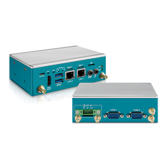
Page 13: Front Panel I/O & Functions
LAN 1 Digital Display In Vecow EIC-2000 series, all I/O connectors are located on the front and top panels. Most of the general connections to computer devices, such as USB, COM, LAN, Console port, Reset button, audio/mic, digital display indicators are placed on the front panel. - Page 14 The USB interface supports 5 Gbps transfer rate complied with Super speed USB specification Rev. 3.0. The top port is a pure USB port, the bottom port can be changed OTG function and pure USB by DIP Switch SW2. ©Vecow EIC-2000 User Manual GETTING TO KNOW YOUR EIC-2000...
- Page 15 Digital Display There are two Ethernet ports auto-sensing 10/100/1000 Mbps in RJ45 connectors on the front side of EIC-2000 series. Both are powered by RTL8211FI-CG Ethernet PHY. The Pin out of LAN1 and LAN2 are listed as following chart. RJ-45 LAN 1 & 2 Pin Out : Pin No.
- Page 16 SIM 2 SIM 1 User Console LAN 2 LAN 1 Digital Display WLAN LED Define LED Status Mini PCIe Card Mini PCIe Transmission Blinking M.2 key B M.2 key B Transmission Blinking ©Vecow EIC-2000 User Manual GETTING TO KNOW YOUR EIC-2000...
- Page 17 HDMI Display provides a method of transferring video and audio data over a TMDS compatible physical link to an audio/visual display device. The Digital Display Port support HDMI V2.0a, it can support 3840 x 2160 @30Hz. ©Vecow EIC-2000 User Manual GETTING TO KNOW YOUR EIC-2000...
- Page 18 Display There two 3.5 mm audio jacks for line-out and mic in function on the front side of EIC-2000. The function is line-out and mic in from left jack to right jack. ©Vecow EIC-2000 User Manual GETTING TO KNOW YOUR EIC-2000...
-
Page 19: Rear Panel I/O & Functions
2 DB-9 Ports in EIC-2000 Series. 2.3.1.1 Power Terminal Block DC-IN COM 2 COM 1 EIC-2000 supports 9V to 55V DC wide range power input by terminal block on the top side. LED Color Definition Chassis Ground ©Vecow EIC-2000 User Manual... - Page 20 CAN with Flexible Data Rate (CAN FD) protocol specification and CAN protocol specification, Version 2.0. CAN Bus of D-SUB Pin Out Table: COM Port Pin No. Definition CANH1 CANL1 ------ ------ CANH2 CANL2 ------ ©Vecow EIC-2000 User Manual GETTING TO KNOW YOUR EIC-2000...
- Page 21 The COM2 can be changed to reserve bus function, there are 6 bits GPIO with voltage 3.3v and one I2C bus with voltage 3.3v. Reserve bus of D-SUB Pin Out Table: COM Port Pin No. CAN Bus GPIO1 GPIO2 GPIO3 GPIO4 GPIO5 GPIO6 ©Vecow EIC-2000 User Manual GETTING TO KNOW YOUR EIC-2000...
-
Page 22: Main Board Connectors & Jumper Locations
RCT Battery COM2 Terminal Resistor Backlight& LVDS PWR SEL WLAN LED2 Reset Botton Console WLAN LED1 User Botton SIM2 M.2 Key B Slot SIM1 Mini PCle Slot Micro SD Card SOM DIMM ©Vecow EIC-2000 User Manual GETTING TO KNOW YOUR EIC-2000... - Page 23 2 : OFF 2 : OFF 2 : ON There is a SW1 set the boot strap in EIC-2000. There are 3 modes selected by SW1, it will be decided to boot up from which mode, default setting “off”. Item...
- Page 24 2 : OFF 2 : OFF 2 : ON There is a SW1 set the boot strap in EIC-2000. There are 3 modes selected by SW1, it will be decided to boot up from which mode, default setting “off”. SW2.x...
- Page 25 2.4.1.3 JUSB1 & JSUB2 : USB Header JUSB1 JUSB2 EIC-2000 is equipped with an USB2.0 header for reserve function. Pin Number Definition PWR_5V USB_D- JUSB1 USB_D+ PWR_5V USB_D- JUSB2 USB_D+ 2.4.1.4 M2_CN1 : M.2 Key B slot M2_CN1 There is a M.2 key B supported with USB 3.0 and PCIE Gen3 signal in EIC- 2000.
- Page 26 V3.3 CONFIG_1 V3.3 SIM_DETECT RFECLKp RFECLKn PCIE_WAKE# PCIE_CLK_REQ PETp0 PCIE_RST# PETn0 PERp0 PERn0 USB3.1-TX+ DEVSLP USB3.1-TX- UIM_PWR UIM_DATA USB3.1-RX+ UIM_CLK USB3.1-RX- UIM_RESET Mechanical Key USB- LED1# USB+ W_DISABLE# FULL_CARD_PWR_OFF V3.3 V3.3 ©Vecow EIC-2000 User Manual GETTING TO KNOW YOUR EIC-2000...
- Page 27 PCIE_TXN SMB_DATA SMB_CLK +1.5V PCIE_RXP PCIE_RXN +V3.3 mPCIE_RST_n Reserved Reserved Reserved Mechanical Key UIM VPP CLK_PCIE_P UIM RESET CLK_PCIE_N UIM CLK UIM DATA PCIE_CLKQ UIM PWR Reserved 1.5V Reserved mPCIE_WAKE_n +V3.3 ©Vecow EIC-2000 User Manual GETTING TO KNOW YOUR EIC-2000...
- Page 28 2.4.1.6 BAT1 : RTC Battery BAT1 The real-time clock of EIC-2000 is powered by a lithium battery. It is equipped with muRata CR2032 210mAh lithium battery. It is recommended that you not replace the lithium battery on your own. If the battery needs to be changed, please contact Vecow RMA service team.
- Page 29 2.4.1.8 J1 : LVDS Connector CON1 EIC-2000 supoorts dual-channel 24-bit LVDS display, up to 1920 x 1080 pixels resolution. The pin assignments of CON1 are listed in following table. The panel power level can be changed by JP1, 5V or 3.3V.
- Page 30 +12V +12V LBKLT_EN LBKLT_CTL 2.4.1.9 CN9 : Power Connector EIC-2000 supports 9V to 55V DC power input by wire to board cable to terminal block connector on the top side. Power Input Pin Out Table Pin No. Definition ©Vecow EIC-2000 User Manual...
- Page 31 2.4.1.10 DIMM1 : SOM Connector DIMM1 The DIMM1 only for EDM-G-IMX8M-PLUS module. ©Vecow EIC-2000 User Manual GETTING TO KNOW YOUR EIC-2000...
-
Page 32: Main Board Jumper Settings
2.5 Main Board Jumper Settings 2.5.1.1 Board Top View of EIC-2000 Main Board with Jumper The fgure below is the top view of EIC-2000 main board which is the main board. It shows the location of the jumpers. To "close" a jumper, you connect the pins with the clip. To "open" a jumper, you remove the clip. - Page 33 Pin 2 and Pin 3 of Pin Header by Jumper, as following configuration table. The default setting are RS-232 mode. COM2 Mode Terminal Resistor Configuration Table : Jumper Function Mode Jumper Function Mode RS-232 RS-232 RS-485 or RS422 RS-422 (120 ohm) (120 ohm) ©Vecow EIC-2000 User Manual GETTING TO KNOW YOUR EIC-2000...
-
Page 34: Chapter 3 System Setup
SYSTEM SETUP 3.1 How to Open Your EIC-2000 Remove the three F-M3x4L(red) and two F-#6-32x6L(blue) screws indicated and separate Cover from the enclosure. ©Vecow EIC-2000 User Manual SYSTEM SETUP... -
Page 35: Installing Nano Sim Card
3.2 Installing Nano SIM Card Inserting SIM card, before make sure the system power not plugged. 3.3 Installing Micro SD Card Inserting SD card ©Vecow EIC-2000 User Manual SYSTEM SETUP... -
Page 36: Installing
3.4.1 M.2 Key B (3052) Install M.2 card into the M.2 slot and fasten PHILLIPS-M3x4L screw. Key B 3052 3.4.2 M.2 Key B (2242_3042) Step 1 Install M.2 extender bracket for 2242/3042 and fasten PHILLIPS-M3x4L screw. ©Vecow EIC-2000 User Manual SYSTEM SETUP... - Page 37 Step 2 Install M.2 card into the M.2 slot and fasten PHILLIPS-M3x4L screw. ©Vecow EIC-2000 User Manual SYSTEM SETUP...
-
Page 38: Installing Mini Pcie
3.5 Installing Mini PCIe Install Mini PCIe card into the slot and fasten PHILLIPS-M2.5x6L screw. ©Vecow EIC-2000 User Manual SYSTEM SETUP... -
Page 39: Installing Antenna Cable
3.6 Installing Antenna Cable Step 1 Remove the rubber corks on the panel. Step 2 Put antenna cable connector into the hole on panel. Step 3 Fasten washer on the antenna cable connector. ©Vecow EIC-2000 User Manual SYSTEM SETUP... -
Page 40: Mounting Your Eic-2000
3.7 Mounting Your EIC-2000 3.7.1 Wall Mount Install wall mount bracket then fasten four pcs F-M3x4L screws. 3.7.2 DIN Rail Mount Install DIN Rail then fasten four pcs F-M3x4L screws. ©Vecow EIC-2000 User Manual SYSTEM SETUP... -
Page 41: Chapter 4 Software Setup
2. Connect the bottom USB port to the host PC, connect the power and power on the EIC-2000. 3. The EIC-2000 will show up on the host system USB list as a new NXP target device. 4. After successfully updating the system software, power off the system. -
Page 42: Appendix A : Power Consumption
M.2 KEY B Quectel RM500Q-AE Mini PCIe Quectel EC25-J Storage 32 GB eMMC LAN1 GigE LAN LAN2 GigE LAN Graphics output HDMI Power plan Default Power Source Chroma 62006P-100-25 Test Program-1 Stress-ng Test Program-2 Memtester ©Vecow EIC-2000 User Manual Appendix A... - Page 43 Current Consumption Current Consumption 1.775A 15.98W 2.089A 18.80W 1.297A 15.56W 1.557A 18.68W NXP i.MX8M ® Plus Arm Quad 0.715A 17.16W 0.834A 20.02W ® Cortex -A53 processor 0.518A 18.65W 0.598A 21.53W 0.411A 19.73W 0.470A 22.56W ©Vecow EIC-2000 User Manual Appendix A...
-
Page 44: Appendix B : Supported Expansion Module List
Worldwide 5G and LTE-A coverage M.2 KEY B RM500Q-AE GPS/GLONASS/BeiDou (Compass)/Galileo Sub 6 GHZ operation Worldwide coverage in single SKU M.2 KEY B Thales MV31-W GPS/GLONASS/Galileo/Beidou LTE Category 4 Quectel EC25 mini PCIe UMTS/HSPA/GSM/GPRS/EDGE Series GPS/GLONASS/BeiDou/Galileo/QZSS ©Vecow EIC-2000 User Manual Appendix B... - Page 45 No part of this publication may be reproduced in any form or by any means, electric, photocopying, or recording, without prior authorization from the publisher. The rights of all the brand names, product names, and trademarks belong to their respective owners. © Vecow Co., Ltd. 2023. All rights reserved.
Need help?
Do you have a question about the EIC-2000 and is the answer not in the manual?
Questions and answers