
Related Manuals for Vecow EAC-3000


Summary of Contents for Vecow EAC-3000
- Page 1 USER USER EAC-3000 Manual Manual NVIDIA ® Jetson AGX Xavier™ Edge AI Computing System 5 GigE LAN with 4 PoE , 8 GMSL2, -20°C to 70°C Operation 1.0.0 Edition 20220912...
- Page 2 Record of Revision Version Date Remark Page Description 1.00 2022/9/12 Official Release ©Vecow EAC-3000 User Manual...
- Page 3 This manual is released by Vecow Co., Ltd. for reference purpose only. All product offerings and specifications are subject to change without prior notice. It does not represent commitment of Vecow Co., Ltd. Vecow shall not be liable for direct, indirect, special, incidental, or consequential damages arising out of the use of the product or documentation or any infringements upon the rights of third parties, which may result from such use.
- Page 4 Fan Sink, with On-board 32GB RAM and 32GB eMMC, 5 GigE EAC-3000F-R32 LAN with 4 PoE+, 4 USB 3.0, 3 M.2, 2 COM RS-232/422/485, 2 SIM, 8 GMSL, 2 CAN Bus, High Performance, Rugged, -20°C to 70°C Extended Temperature ©Vecow EAC-3000 User Manual...
- Page 5 GMSL Camera with Fakra-Z connector M.2 Storage Module M.2 Key M/Key B PCIe Storage Module 5G Module 5G Module with Antenna 4G Module 4G/GPS Module with Antenna WiFi & Bluetooth Module WiFi & Bluetooth Module with Antenna ©Vecow EAC-3000 User Manual...
-
Page 6: Table Of Contents
2.4 Main Board Connector & Jumper Locations 2.5 Main Board Jumper Settings 2.6 Ignition Control CHAPTER 3 SYSTEM SETUP 3.1 How to Open Your EAC-3000/EAC-3000F 3.2 Installing Nano SIM Card 3.3 Installing Micro SD Card 3.4 Installing M.2 3.5 Installing Antenna Cable 3.6 Mounting Your EAC-3000/EAC-3000F... - Page 7 CHAPTER 4 SOFTWARE SETUP 4.1 Peripheral Interface Guide 4.2 Determine Available Drive Space 4.3 Install the CUDA package 4.4 Flash image to Your EAC-3000/EAC-3000F 4.5 Software Ignition Control APPENDIX A : GMSL Camera Guide APPENDIX B : Power Consumption APPENDIX C : Supported Expansion Module List...
-
Page 8: Chapter 1 General Introduction
GENERAL INTRODUCTION 1.1 Overview Vecow EAC-3000 Series is an Arm-based Edge AI Computing System. Powered ® by NVIDIA Jetson AGX Xavier™ system-on-module, Vecow EAC-3000 Series delivers great power efficiency in a small form factor. Featuring 8 GMSL2 automotive cameras via rugged FAKRA-Z connectors, the EAC-3000 is well suited for industrial and outdoor environments. -
Page 9: Features
• 2 CAN Bus support Flexible Data-rate, 2 COM RS-232/422/485 • M.2 supports 5G/4G/LTE/WiFi/BT/GPS • Tested to MIL-STD-810G for shock and vibration • Support 24/7 secure remote monitoring, control, and OTA deployment empowered by Allxon ©Vecow EAC-3000 User Manual GENERAL INTRODUCTION... -
Page 10: Product Specification
1.3 Product Specification 1.3.1 Specifications of EAC-3000 System ® NVIDIA Jetson Xavier™ AGX System-On-Module ® Processor • 8-core NVIDIA Carmel ARM v8.2 64-bit CPU • 512-core NVIDIA Volta™ GPU with 64 Tensor Cores EAC-3000-R64: LPDDR4x DRAM 64GB Memory EAC-3000-R32: LPDDR4x DRAM 32GB Storage eMMC 5.1, 32 GB... - Page 11 -40°C to 85°C (-40°F to 185°F) Humidity 5% to 95% Humidity, non-condensing Relative Humidity 95% at 70°C Shock Operating, MIL-STD-810G, Method 516.7, Procedure I Operating, MIL-STD-810G, Method 514.7, Procedure I, Vibration Category 4 CE, FCC, EN50155, EN50121-3-2 ©Vecow EAC-3000 User Manual GENERAL INTRODUCTION...
-
Page 12: Specifications Of Eac-3000F
• 1 Reset Button • 1 Micro USB console debug port Micro USB • 1 Micro USB OS flash port 2 SIM Card Socket Power, HDD, 2 User Programming Antenna 6 Antenna for 5G/WiFi/4G/LTE/GPRS/UMTS Expansion ©Vecow EAC-3000 User Manual GENERAL INTRODUCTION... - Page 13 -40°C to 85°C (-40°F to 185°F) Humidity 5% to 95% Humidity, non-condensing Relative Humidity 95% at 70°C Shock Operating, MIL-STD-810G, Method 516.7, Procedure I Operating, MIL-STD-810G, Method 514.7, Procedure I, Vibration Category 4 CE, FCC, EN50155, EN50121-3-2 ©Vecow EAC-3000 User Manual GENERAL INTRODUCTION...
-
Page 14: Mechanical Dimension
1.4 Mechanical Dimension 1.4.1 Dimensions of EAC-3000 Unit : mm (inch) 260.8 (10.27) 239.0 (9.41) 212.6 (8.37) 149.0 (5.87) 1.4.2 Dimensions of EAC-3000F Unit : mm (inch) 260.8 (10.27) 239.0 (9.41) 212.6 (8.37) 149.0 (5.87) ©Vecow EAC-3000 User Manual GENERAL INTRODUCTION... -
Page 15: Chapter 2 Getting To Know Your
EAC-3000/EAC-3000F 2.1 Packing List 2.1.1 EAC-3000 Packing List Item Description EAC-3000 Edge AI Computing System (According to the configuration of your order, EAC-3000 series may contain micro SD and M.2 modules. Please verify these items if necessary.) Item Description Outlook... -
Page 16: Eac-3000F Packing List
PHILLPIS M3x4L, M.2 socket 53-2426204-80B Ni+Ny Terminal block DC-IN 51-2611R03-S1N 3-pin(7.62mm) Wall mount Wall mount 62-03P1053-0BA EAC-3000 bracket Terminal block 51-2211R03-S01 3-pin(3.5mm) Fasten Flat #6-32x6L, wall mount 53-I000350-311 Black+Ny bracket to EAC-3000 ©Vecow EAC-3000 User Manual GETTING TO KNOW YOUR EAC-3000/EAC-3000F... -
Page 17: Front Panel I/O & Functions
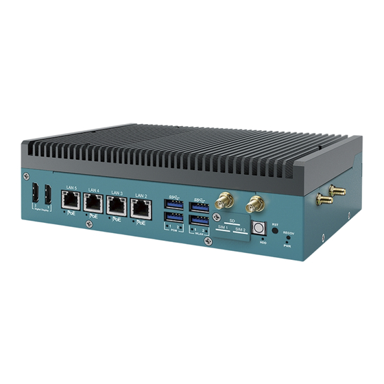
2.2 Front Panel I/O & Functions 2.2.1 Functions of EAC-3000 In Vecow EAC-3000 series, Most of the I/O connectors are located on the front panels. Most of the general connections to computer devices, such as USB, LAN, Digital Display Port, Force Recovery button, Power Button,Reset Button, indicators are placed on the front panel. - Page 18 To power off the system, you can either command shutdown by OS operation, or just simply press the power button. 2.2.1.4 Micro SD The external Micro SD card provides additional storage expansion. It is located behind the cover-plate on the front panel. ©Vecow EAC-3000 User Manual GETTING TO KNOW YOUR EAC-3000/EAC-3000F...
- Page 19 2.2.1.6 USB 3.2 Gen1 There are 4 USB 3.2 Gen1 connections available supporting up to 5Gb per second data rate in the front panel of EAC-3000. It is also compliant with the requirements of Speed (SS), High Speed (HS), Full Speed (FS) and Low Speed (LS).
- Page 20 2.2.1.7 LAN2~LAN5: PoE Ports There are 4 RJ45 connectors in the front panel of EAC-3000. It supports IEEE 802.3at (PoE+) Power over Ethernet (PoE) connection delivering up to 37W/54V per port and 1000BASE-T gigabit data signals over standard Ethernet Cat 5/ ®...
- Page 21 Yellow POE_LED3 POE_LED1 POE_LED2 POE_LED4 POE LED LED Color POE Status POE_LED1 Solid Orange PoE ON POE_LED2 Solid Orange PoE ON POE_LED3 Solid Orange PoE ON POE_LED4 Solid Orange PoE ON ©Vecow EAC-3000 User Manual GETTING TO KNOW YOUR EAC-3000/EAC-3000F...
- Page 22 Orange-HDD LED : A SSD Storage LED. If the LED is on, it indicates that the system's storage is functional. If it is off, it indicates that the system's storage is not functional. If it is flashing, it indicates data access activities are in progress. ©Vecow EAC-3000 User Manual GETTING TO KNOW YOUR EAC-3000/EAC-3000F...
- Page 23 There are two Programmable LEDs,user can define the state of the led by himself. 2.2.2 Functions of EAC-3000F EAC-3000F is the same as EAC-3000, the difference is that EAC-3000F has Fan Sink. ©Vecow EAC-3000 User Manual GETTING TO KNOW YOUR EAC-3000/EAC-3000F...
-
Page 24: Rear Panel I/O & Functions
2.3 Rear Panel I/O & Functions 2.3.1 Functions of EAC-3000 In Vecow EAC-3000 series, Some of the I/O connectors are located on the rear panels. Such as GMSL Camera, LAN, CAN Port, COM Port, Power input,Debug Port,Flash Port indicators are placed on the rear panel. - Page 25 System debug Port,Micro USB to UART that connects to the SOM serial console. Console Port Pin Out of Micro USB : CAN1 CAN2 Pin No. Function Pin No. Function CAN1_H CAN2_H CAN1_L CAN2_L ©Vecow EAC-3000 User Manual GETTING TO KNOW YOUR EAC-3000/EAC-3000F...
- Page 26 2.3.1.4 LAN1 10/100/1000 Mbps Ethernet Port This is 8-pin RJ-45 jacks supporting 10/100/1000 Mbps Ethernet connections on the rear panel of EAC-3000. LAN 1 is powered by Microchip USB3.2 to Giga ETH Controller. 2.3.1.5 COM Port COM 1,2 can be configured for RS-232, RS-422, or RS-485 with auto flow control communication.
- Page 27 USB_DATA+ 2.3.1.7 Flash Port The EAC-3000 USB Recovery mode provides an alternate boot device (USB). In this mode, the system is connected to a host system and boots over USB. This is used when a new image needs to be flashed. USB0 must be available to use as USB Device for USB Recovery Mode.
- Page 28 2.3.1.8 GMSL Camera Port There are eight FAKRA connectors in the rear side of EAC-3000. Each camera connects to the EAC-3000 through a single coax cable. Using GMSL2 (Gigabit Multimedia Serial Link) connections, the cameras are connected to a two-port deserializer.
-
Page 29: Main Board Connector & Jumper Locations
LAN1 CN14 DC_IN1 SYS_FAN1 JCOM1 JP20 JSPI1 JGPIO1 JPOE_PWR1 M2E_CN1 JGPIO2 SUMITB1 JAUDIO1 JIGNMODE1 M2B_CN1 CN23 CN10 CN11 BOT View of MB M2M_CN1 POE_LED4 POE_LED2 HDD_LED1 POE_LED3 POE_LED1 LED1 LED2 POWER_LED1 ©Vecow EAC-3000 User Manual GETTING TO KNOW YOUR EAC-3000/EAC-3000F... - Page 30 2.4.1.1 JCOM1,JCOM2 Connector EAC-3000 provides 2 serial ports (COM1-COM2) headers for internal COM port cable and the pin define are listed in the following table. Pin No. Signal Name Pin No. Signal Name Ground 2.4.1.2 Fan Connector (SYS_FAN1) SYS_FAN1 Fan power connector supports for additional thermal requirements. The pin assignments of SYS_FAN1 is listed in the following table.
- Page 31 M.2 KEY E : USB 2.0/PCIe x1 M.2 key E connector is suitable for applications that use wireless connectivity including Wi-Fi, Bluetooth, NFC of GNSS. Module card types include 2230. Pin Out : Pin No. Signal Name Pin No. Signal Name +V3.3_AUX +V3.3_AUX PEWAKE ©Vecow EAC-3000 User Manual GETTING TO KNOW YOUR EAC-3000/EAC-3000F...
- Page 32 Pin No. Signal Name Pin No. Signal Name I2C_ALERT# I2C_CLK I2C_DATA PCIE_WAKE# PCIE_CLK_REQ0# PLTRST# SUS_CLK PCIE_100M_CLK__N PCIE_100M_CLK__P PCIE_RX_N PCIE_RX_P PCIE_TX_N PCIE_TX_P Mechanical Key USB- LED1# USB+ +V3.3_AUX +V3.3_AUX ©Vecow EAC-3000 User Manual GETTING TO KNOW YOUR EAC-3000/EAC-3000F...
- Page 33 The pin assignments of M2B_CN1 are listed in the following table: Pin Out : Pin No. Signal Name Pin No. Signal Name V3.3 V3.3 CONFIG_1 V3.3 SIM_DETECT RFECLKp RFECLKn PCIE_WAKE# PCIE_CLK_REQ PETp0 PLTRST# PETn0 PERp0 PERn0 ©Vecow EAC-3000 User Manual GETTING TO KNOW YOUR EAC-3000/EAC-3000F...
- Page 34 Pin No. Signal Name Pin No. Signal Name PETp1/USB3.1-TX+ DEVSLP PETn1/USB3.1-TX- UIM_PWR UIM_DATA PERp1/USB3.1-RX+ UIM_CLK PERn1/USB3.1-RX- UIM_RESET Mechanical Key USB- LED1# USB+ W_DISABLE# FULL_CARD_PWR_OFF V3.3 V3.3 ©Vecow EAC-3000 User Manual GETTING TO KNOW YOUR EAC-3000/EAC-3000F...
- Page 35 B_PER_N0 C_CLKP B_CLKP C_CLKN B_CLKN CPRSNT#/C_PE_CLKREQ# C_PET_P0 C_PER_P0 C_PET_N0 C_PER_N0 C_PET_P1 C_PER_P1 C_PET_N1 C_PER_N1 C_PET_P2 C_PER_P2 C_PET_N2 C_PER_N2 C_PET_P3 C_PER_P3 C_PET_N3 C_PER_N3 PERST# WAKE# Reserved Reserved Reserved +3.3V +3.3V +3.3V +5V_AUX ©Vecow EAC-3000 User Manual GETTING TO KNOW YOUR EAC-3000/EAC-3000F...
- Page 36 2.4.1.7 J1 : Jetson AGX Xavier Connector only for Jetson Xavier AGX module. 2.4.1.8 JSPI1 : SPI/I2C Signal Connector This is SPI+I2C headers, it offered SPI Bus and I2C Bus, in EAC-3000 series. Pin No. JSPI1 Definition +3.3V SPI1_MOSI SPI1_MISO...
- Page 37 There is a 16-bit GPIO connector in the Top side. Each GPIO channel can be configuration GPI or GPO. Pin No. JGPIO1 Definition Pin No. JGPIO2 Definition +3.3V +3.3V GPIO06 GPIO19 GPIO08 GPIO23 GPIO10 GPIO24 GPIO12 GPIO25 GPIO14 GPIO28 GPIO18 GPIO31 ------------- ------------- ------------- GPIO36 ©Vecow EAC-3000 User Manual GETTING TO KNOW YOUR EAC-3000/EAC-3000F...
- Page 38 The system's real-time clock is powered by a lithium battery. It is Equipped with Panasonic BR2032 190mAh lithium battery. It is recommended that you not replace the lithium battery on your own. If the battery needs to be changed, please contact the Vecow RMA service team. BAT1 2.4.1.12 M.2 KEY-M (M2M_CN1) M.2 key M Connector (2280, PCIe Gen3x2)
-
Page 39: Main Board Jumper Settings
2.5 Main Board Jumper Settings 2.5.1.1 Board Top View of EAC-3000 Main Board with Jumper. The figure below is the top view of EAC-3000 main board which is the main board. It shows the location of the jumpers. JP20 JPOE_PWR1 You may configure your card to match the needs of your application by setting jumpers. - Page 40 Pin No. Definition MODE(Default) S/W MODE 2.5.1.3 JPOE_PWR1 : POE Power On Voltage Select JPOW_PWR1 Jumper Setting Function PoE Power On Standby Mode JPOE_PWR1 PoE Power On Main Power On Mode (default) ©Vecow EAC-3000 User Manual GETTING TO KNOW YOUR EAC-3000/EAC-3000F...
- Page 41 JP20 The GMSL2 forward link has a fixed link rate of 3Gbps or 6Gbps. JP1 and JP3 Pin define : Pin No. Definition FAN Operation Voltage 5V FAN Operation Voltage 12V ©Vecow EAC-3000 User Manual GETTING TO KNOW YOUR EAC-3000/EAC-3000F...
-
Page 42: Ignition Control
The built-in MCU monitors the ignition signal and turns on/off the system according to pre-defined on/off delay period. 2.6.1 Adjust Ignition Control Modes EAC-3000 series provides 16 modes of different power on/off delay periods adjustable via SW1 switch. The default DIP switch is set to 0 in ATX power mode. - Page 43 Please find below the general wiring configuration. Pin No. Definition Ignition (IGN) For testing purpose, you can refer to the picture blow to simulate ignition signal input controlled by a latching switch. ©Vecow EAC-3000 User Manual GETTING TO KNOW YOUR EAC-3000/EAC-3000F...
-
Page 44: Chapter 3 System Setup
SYSTEM SETUP 3.1 How to Open Your EAC-3000/EAC-3000F Remove four I-M3x6L screws and pick up Heat Sink. (EAC-3000F careful to the fan cable) ©Vecow EAC-3000 User Manual SYSTEM SETUP... - Page 45 ©Vecow EAC-3000 User Manual SYSTEM SETUP...
-
Page 46: Installing Nano Sim Card
3.2 Installing Nano SIM Card Step 1 Remove one F-M3x4L screw on SD/SIM cover. Step 2 Inserting SIM card, make sure the system power is not plugged. ©Vecow EAC-3000 User Manual SYSTEM SETUP... -
Page 47: Installing Micro Sd Card
3.3 Installing Micro SD Card Step 1 Remove one F-M3x4L screw on SD/SIM cover. Step 2 Inserting SD card. ©Vecow EAC-3000 User Manual SYSTEM SETUP... -
Page 48: Installing
3.4 Installing M.2 3.4.1 M.2 Key B (3042) M.2 Key E (2230) Install M.2 card into the M.2 slot and fasten PHILLPIS-M3x4L screw. Key E 2230 Key B 3042 ©Vecow EAC-3000 User Manual SYSTEM SETUP... - Page 49 3.4.2 M.2 Key B (3052) Step 1 Change the stud position. Step 2 Install M.2 card into the M.2 slot and fasten PHILLPIS-M3x4L screw. ©Vecow EAC-3000 User Manual SYSTEM SETUP...
- Page 50 3.4.3 M.2 Key M (2280) Step 1 Remove two F-M3x4L screws on Storage cover. Step 2 Install M.2 card into the M.2 slot and fasten PHILLPIS-M3x4L screw. Key M 2280 ©Vecow EAC-3000 User Manual SYSTEM SETUP...
-
Page 51: Installing Antenna Cable
3.5 Installing Antenna Cable Step 1 Remove the rubber corks on the panel. Step 2 Put antenna cable connector into the hole on panel. Step 3 Fasten washer on the antenna cable connector. ©Vecow EAC-3000 User Manual SYSTEM SETUP... -
Page 52: Mounting Your Eac-3000/Eac-3000F
3.6 Mounting Your EAC-3000/EAC-3000F Wall Mount Install wall mount bracket then fasten four pcs #6-32x6L screws. VESA Mount Install VESA mount then fasten four pcs #6-32x6L screws. ©Vecow EAC-3000 User Manual SYSTEM SETUP... - Page 53 DIN Rail Mount Install din rail kit then fasten four pcs #6-32x6L screws. ©Vecow EAC-3000 User Manual SYSTEM SETUP...
-
Page 54: Chapter 4 Software Setup
SOFTWARE SETUP 4.1 Peripheral Interface Guide 4.1.1 UART EAC-3000/EAC-3000F have two UARTs, you can access the following path to find an application to config the UART type : $ cd /usr/src/tools/EAC-3000/uart/ 4.1.2 CAN Bus You can access the following path to find a CAN FD example : $ cd /usr/src/tools/EAC-3000/canbus/ 4.1.3 I2S... -
Page 55: Determine Available Drive Space
To determine the amount of available drive space, you can issue the following commands : $ sudo df -h 4.3 Install the CUDA package To install the CUDA package on EAC-3000/EAC-3000F, you can issue the following commands : $ sudo apt update $ sudo apt install nvidia-cuda 4.4 Flash image to Your EAC-3000/EAC-3000F... - Page 56 Continue to hold the "RECOV" button for two seconds, and release. Step.3 Now device is in recovery mode, issue “lsusb” command on host PC will find a new USB device : ©Vecow EAC-3000 User Manual SOFTWARE SETUP...
- Page 57 4.4.3 Flash image to the EAC-3000/3000F Step.1 Open a terminal on host PC, then access the package folder you extracted in the 4.4.1 section. Step.2 Issue the following command to flash the image : $ sudo ./nvmflash.shh Step.3 Once the process finished, you should see the following log : ©Vecow EAC-3000 User Manual...
-
Page 58: Software Ignition Control
4.5 Software Ignition Control Vecow provides Ignition Software to control power on/off delay periods. To activte software ignition control, you need to adjust the JIGNMODE1 jumper to 2-3. You can access the following path to find an application for software... -
Page 59: Appendix A : Gmsl Camera Guide
Only the verified cameras shown below are supported in default. Verified Cameras List - Otobrite oToCAM264ISP The verified cameras list may be subject to change without notice. For further support on GMSL cameras, please contact the Vecow support team. ©Vecow EAC-3000 User Manual APPENDIX A : GMSL Camera Guide... -
Page 60: Appendix B : Power Consumption
Intel 8265NGW LAN 1 1.0 Gbps LAN 2 1.0 Gbps LAN 3 1.0 Gbps LAN 4 1.0 Gbps Graphics Output HDMI Power Plan Default (15W TDP mode) Power Source Chroma 62006P-100-25 Test Program Stress-ng Test ©Vecow EAC-3000 User Manual Appendix B... - Page 61 Run BurnInTest/Stress-ng Test Input Current Consumption Current Consumption 1.917A 17.26W 2.915A 26.24W 1.508A 18.10W 2.182A 26.19W ARMv8 Processor 0.789A 18.94W 1.142A 27.42W rev 0 (v8l) × 4 0.564A 20.32W 0.814A 29.29W 0.472A 23.69W 0.607A 30.35W ©Vecow EAC-3000 User Manual Appendix B...
-
Page 62: Appendix C : Supported Expansion Module List
Type Model Support Standard IEEE 802.11a/b/g/n/ac 2T2R M.2 KEY E Azurewave AW-CB375NF Bluetooth 5.0 SparkLAN IEEE 802.11a/b/g/n/ac 2T2R M.2 KEY E WNFT-237ACN(BT) Bluetooth 5.0 IEEE 802.11a/b/g/n/ac 2T2R M.2 KEY E Intel 8265NGW Bluetooth 4.2 ©Vecow EAC-3000 User Manual Appendix C... - Page 63 No part of this publication may be reproduced in any form or by any means, electric, photocopying, or recording, without prior authorization from the publisher. The rights of all the brand names, product names, and trademarks belong to their respective owners. © Vecow Co., Ltd. 2022. All rights reserved.
Need help?
Do you have a question about the EAC-3000 and is the answer not in the manual?
Questions and answers