
Related Manuals for Vecow RCX-2000 PEG


Summary of Contents for Vecow RCX-2000 PEG
- Page 1 USER USER RCX-2000 PEG Manual Manual Intel ® Xeon ® /Core™ i7/i5/i3 AI Computing System Workstion-grade, NVIDIA ® Tesla ® /Quadro ® /GeForce ® /AMD Radeon ™ Grraphics 1.00 Edition 20220121...
- Page 2 Record of Revision Version Date Page Description Remark 1.00 2022/1/21 Official Release ©Vecow RCX-2000 PEG User Manual...
- Page 3 This manual is released by Vecow Co., Ltd. for reference purpose only. All product offerings and specifications are subject to change without prior notice. Vecow Co., Ltd. is under no legal commitment to the details of this document. Vecow shall not be liable for direct, indirect, special, incidental, or consequential damages arising out of the use of this document, the products, or any third party infringements, which may result from such use.
- Page 4 Processor, 1 GigE LAN, 1 2.5 GigE LAN, 6 USB 3.2 Gen 2, 4 COM, 3 SIM, 2 PCIe x8 (Gen4) Slot, RCX-2750R-PEG 3 PCIe x4 (Gen3) Slot, 3 M.2, 32 Isolated DIO, 4 Front-access SSD Tray ©Vecow RCX-2000 PEG User Manual...
- Page 5 DIN-Rail Mounting M.2 Storage Module M.2 Key M/Key B PCIe Storage Module 5G Module 5G Module with Antenna 4G Module Mini PCIe 4G/GPS Module with Antenna WiFi & Bluetooth WiFi & Bluetooth Module with Antenna ©Vecow RCX-2000 PEG User Manual...
-
Page 6: Table Of Contents
2.5 Ignition Control CHAPTER 3 SYSTEM SETUP 3.1 How to open your RCX-2000 3.2 Installing CPU 3.3 Installing DDR4 SO-DIMM Modules 3.4 Installing Mini PCIe Card 3.5 Installing SIM Card 3.6 Installing PCI/PCIe Card 3.7 Installing SSD/HHD ©Vecow RCX-2000 PEG User Manual... - Page 7 3.8 Installing Antenna Cable 3.9 Mounting Your RCX-2000 PEG 3.10 Installing Hold-down Kit CHAPTER 4 BIOS SETUP 4.1 Entering BIOS Setup 4.2 Main Menu 4.3 Advanced Functions 4.4 Chipset Functions 4.5 Security Functions 4.6 Boot Functions 4.7 Save & Exit...
-
Page 8: Chapter 1 General Introduction
AMD graphics engine, Vecow RCX-2000 PEG provides scalability of expansion with 3 PCIe, 2 Mini PCIe, 4 M.2. In addition, Vecow RCX-2000 PEG offers a variety of interfaces including 2 GigE LAN, 6 USB, 4 COM, 3 SIM and 4 SSD tray for storage. -
Page 9: Features
• Multiple 5G/WiFi 6/4G/LTE/GPRS/UMTS, TPM 2.0, vPRO • DC 9V to 55V Power Input, Software Ignition Control • Optional VHub AIoT Solution Service supports OpenVINO based AI accelerator and advanced Edge AI applications ©Vecow RCX-2000 PEG User Manual GENERAL INTRODUCTION... -
Page 10: Product Specification
® Audio Codec Realtek ALC888S-VD, 7.1 Channel HD Audio Audio Interface 1 Mic-in, 1 Line-out Ethernet LAN 1 Intel ® I219LM Gigabit LAN supports iAMT 12.0 ® LAN 2 Intel I225IT 2.5G LAN ©Vecow RCX-2000 PEG User Manual GENERAL INTRODUCTION... - Page 11 Temperature Humidity 5% to 95% humidity, non-condensing Relative Humidity 95% at 75°C • IEC 61373 : 2010 Shock/Vibration • Railway Applications : Rolling Stock Equipment, Shock and Vibration Tests CE, FCC, EN50155, EN50121-3-2 ©Vecow RCX-2000 PEG User Manual GENERAL INTRODUCTION...
-
Page 12: Specifications Of Rcx-2330R Peg
® Audio Codec Realtek ALC888S-VD, 7.1 Channel HD Audio Audio Interface 1 Mic-in, 1 Line-out Ethernet ® LAN 1 Intel I219LM Gigabit LAN supports iAMT 12.0 ® LAN 2 Intel I225IT 2.5G LAN ©Vecow RCX-2000 PEG User Manual GENERAL INTRODUCTION... - Page 13 Temperature Humidity 5% to 95% humidity, non-condensing Relative Humidity 95% at 75°C • IEC 61373 : 2010 Shock/Vibration • Railway Applications : Rolling Stock Equipment, Shock and Vibration Tests CE, FCC, EN50155, EN50121-3-2 ©Vecow RCX-2000 PEG User Manual GENERAL INTRODUCTION...
-
Page 14: Specifications Of Rcx-2750 Peg
® Audio Codec Realtek ALC888S-VD, 7.1 Channel HD Audio Audio Interface 1 Mic-in, 1 Line-out Ethernet ® LAN 1 Intel I219LM Gigabit LAN supports iAMT 12.0 ® LAN 2 Intel I225IT 2.5G LAN ©Vecow RCX-2000 PEG User Manual GENERAL INTRODUCTION... - Page 15 Temperature Humidity 5% to 95% humidity, non-condensing Relative Humidity 95% at 75°C • IEC 61373 : 2010 Shock/Vibration • Railway Applications : Rolling Stock Equipment, Shock and Vibration Tests CE, FCC, EN50155, EN50121-3-2 ©Vecow RCX-2000 PEG User Manual GENERAL INTRODUCTION...
-
Page 16: Specifications Of Rcx-2750R Peg
® Audio Codec Realtek ALC888S-VD, 7.1 Channel HD Audio Audio Interface 1 Mic-in, 1 Line-out Ethernet ® LAN 1 Intel I219LM Gigabit LAN supports iAMT 12.0 ® LAN 2 Intel I225IT 2.5G LAN ©Vecow RCX-2000 PEG User Manual GENERAL INTRODUCTION... - Page 17 Temperature Humidity 5% to 95% humidity, non-condensing Relative Humidity 95% at 75°C • IEC 61373 : 2010 Shock/Vibration • Railway Applications : Rolling Stock Equipment, Shock and Vibration Tests CE, FCC, EN50155, EN50121-3-2 ©Vecow RCX-2000 PEG User Manual GENERAL INTRODUCTION...
-
Page 18: Supported Cpu List
1.4 Supported CPU List Series Model Cores Turbo TDP (W) ECC RAM Intel ® Xeon ® W-1350 i7-11700 i7-11700T ® Intel Core™ i5-11500 i5-11500T ©Vecow RCX-2000 PEG User Manual GENERAL INTRODUCTION... -
Page 19: Mechanical Dimension
1.5 Mechanical Dimension 1.5.1 Dimensions of RCX-2330-PEG Unit : mm (inch) 208.7 (8.22) 206.0 (8.11) 160.0 (6.30) ©Vecow RCX-2000 PEG User Manual GENERAL INTRODUCTION... -
Page 20: Dimensions Of Rcx-2330R-Peg
1.5.2 Dimensions of RCX-2330R-PEG Unit : mm (inch) 208.7 (8.22) 206.0 (8.11) 160.0 (6.30) ©Vecow RCX-2000 PEG User Manual GENERAL INTRODUCTION... -
Page 21: Dimensions Of Rcx-2750-Peg
1.5.3 Dimensions of RCX-2750-PEG Unit : mm (inch) 253.9 (10.00) 206.0 (8.11) 160.0 (6.30) ©Vecow RCX-2000 PEG User Manual GENERAL INTRODUCTION... -
Page 22: Dimensions Of Rcx-2750R-Peg
1.5.4 Dimensions of RCX-2750R-PEG Unit : mm (inch) 253.9 (10.00) 206.0 (8.11) 160.0 (6.30) ©Vecow RCX-2000 PEG User Manual GENERAL INTRODUCTION... -
Page 23: Chapter 2 Getting To Know Your Rcx-2000
2.1 Packing List 2.1.1 RCX-2330 PEG Packing List Item Description RCX-2000-PEG AI Computing System (According to the configuration you order, the RCX-2000 PEG series may contain SSD/HDD and DDR4 SO-DIMM. Please verify these items if necessary.) Vecow Drivers & Utilities DVD Item... - Page 24 2.1.2 RCX-2330R PEG Packing List Item Description RCX-2000-PEG AI Computing System (According to the configuration you order, the RCX-2000 PEG series may contain SSD/HDD and DDR4 SO-DIMM. Please verify these items if necessary.) Vecow Drivers & Utilities DVD SSD/HDD Tray Key...
- Page 25 2.1.3 RCX-2750 PEG Packing List Item Description RCX-2000-PEG AI Computing System (According to the configuration you order, the RCX-2000 PEG series may contain SSD/HDD and DDR4 SO-DIMM. Please verify these items if necessary.) Vecow Drivers & Utilities DVD Item Description...
- Page 26 2.1.4 RCX-2750R PEG Packing List Item Description RCX-2000-PEG AI Computing System (According to the configuration you order, the RCX-2000 PEG series may contain SSD/HDD and DDR4 SO-DIMM. Please verify these items if necessary.) Vecow Drivers & Utilities DVD SSD/HDD Tray Key...
-
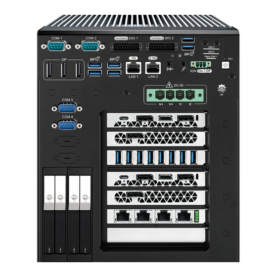
Page 27: Front Panel I/O Functions
2.2 Front Panel I/O Functions In Vecow's RCX-2000 PEG family, all I/O connectors are located on the front panel. Most of the general connections to the computer device, such as audio, USB, LAN, COM Port, Isolated DIO, Display Port, and any additional storage, are placed on the front panel. - Page 28 Please do note that a four-second interval between each two power-on/power-off operation is necessary in normal working status. (For example, once turning off the system, you have to wait for four seconds to initiate another power-on operation). ©Vecow RCX-2000 PEG User Manual GETTING TO KNOW YOUR RCX-2000...
- Page 29 • Twinkling : Data transferring. Green Power System power status (on/off) 2.2.4 Display Port Onboard Display Port support auxiliary channel dual mode, connection supports up to 4096 x 2304 resolution at 60Hz. ©Vecow RCX-2000 PEG User Manual GETTING TO KNOW YOUR RCX-2000...
- Page 30 There are 6 USB 3.2 Gen2 Type A connections available supporting up to 10GB per second data rate in the front side of RCX-2000 PEG. It also compliant with the requirements of Super Speed (SS), high speed (HS), full speed (FS) and low speed (LS).
- Page 31 Orange Orange Green LAN1_CN1 Twinkling Twinkling Twinkling Left Yellow Yellow Yellow Yellow Green/ Solid Solid Right Orange Orange Green LAN2_CN1 Twinkling Twinkling Twinkling Twinkling Left Yellow Yellow Yellow Yellow Yellow ©Vecow RCX-2000 PEG User Manual GETTING TO KNOW YOUR RCX-2000...
- Page 32 2.2.9 Front-access SSD/HDD Tray There are four front-access 2.5" SSD/HDD trays on the front side of RCX-2000. Press the trigger to open the SSD/HDD tray which has up to 8TB available. ©Vecow RCX-2000 PEG User Manual GETTING TO KNOW YOUR RCX-2000...
- Page 33 You could turn on or off the system power by using this contact. This terminal block IGNITION supports dual function on soft power-on/ power-off (instant off or delay four seconds), and suspend mode. ©Vecow RCX-2000 PEG User Manual GETTING TO KNOW YOUR RCX-2000...
- Page 34 • 3-KVRMS Isolation for 1 minute per UL 1577 • CSA Component Acceptance Notice 5A, IEC 60950-1 and IEC 61010-1 End Equipment Standards PIN 1 ~ 8 PIN 11 ~ 18 • GB4943.1-2011 CQC Certified ©Vecow RCX-2000 PEG User Manual GETTING TO KNOW YOUR RCX-2000...
- Page 35 OUTPUT 8 SIO_GPO0 OUTPUT 9 SIO_GPO1 OUTPUT 10 SIO_GPO2 OUTPUT 11 SIO_GPO3 OUTPUT 12 SIO_GPO4 OUTPUT 13 SIO_GPO5 OUTPUT 14 SIO_GPO6 OUTPUT 15 SIO_GPO7 GND_ISO_DIO2 External 6-40VDC (NPN) External 6-48VDC (PNP) ©Vecow RCX-2000 PEG User Manual GETTING TO KNOW YOUR RCX-2000...
- Page 36 DO Signal circuit in SINK mode (NPN) Source (PNP) DIO_VDC (20) LOAD 7.2K ISOLATION 6-40V (11) (300mA) 1.5K GNDI GNDO GNDO (10.19) Internal Circuit External Device GNDO DO Signal circuit in source mode (PNp) ©Vecow RCX-2000 PEG User Manual GETTING TO KNOW YOUR RCX-2000...
- Page 37 (9-wire) (3-wire) TXD- TXD- DATA- TXD+ TXD+ DATA+ RXD+ RXD+ ----------- RXD- RXD- ----------- 1, 2 3, 4 ----------- RTS- ----------- ----------- RTS+ ----------- ----------- CTS+ ----------- ----------- CTS- ----------- ©Vecow RCX-2000 PEG User Manual GETTING TO KNOW YOUR RCX-2000...
-
Page 38: Main Board Expansion Connectors
2.3 Main Board Expansion Connectors 2.3.1 Front View of RCX-2000 PEG Main Board With Connector Location ATX8PIN_1 ATX8PIN_2 DCIN_CN1 SODIMM_3 SODIMM_4 SATA3 SATA1 BAT_CN1 SODIMM_1 SODIMM_2 SATA4 CPU_PEG_CN1 SATA2 HDD_PWR_J3 HDD_PWR_J1 M2M_CN1 JUSB1 HDD_PWR_J4 HDD_PWR_J2 CPU_FAN1 BIOS_CN1 SYS_FAN1 JIGN_FW1 SYS_FAN2... - Page 39 2.3.2 Rear View of RCX-2000 Main Board With Connector Location Super I/O BTN1 M2B_SIM1 ©Vecow RCX-2000 PEG User Manual GETTING TO KNOW YOUR RCX-2000...
- Page 40 CPU_FAN1, SYS_FAN1, SYS_FAN2 are listed in the following table : CPU_FAN1 SYS_FAN1, SYS_FAN2 Pin No. Description Pin No. Description +12V (up to 1A) +12V (up to 1A) Fan speed sensor Fan speed sensor Fan PWM Fan PWM ©Vecow RCX-2000 PEG User Manual GETTING TO KNOW YOUR RCX-2000...
- Page 41 Panasonic CR2032 220mAh lithium battery. It is recommended that you do not replace the lithium battery on your own. If the battery needs to be changed, please contact the Vecow RMA service team. ©Vecow RCX-2000 PEG User Manual GETTING TO KNOW YOUR RCX-2000...
- Page 42 Function Pin No. Function CLK100M_CPU_3_N CLK100M_CPU_2_N CLK100M_CPU_3_P CLK100M_CPU_2_P CLK100M_CPU_1_N PCIE24_RX_N CLK100M_CPU_1_P PCIE24_RX_P PCIE24_TX_N PCIE23_RX_N PCIE24_TX_P PCIE23_RX_P PCIE23_TX_N PCIE22_RX_N PCIE23_TX_P PCIE22_RX_P PCIE22_TX_N PCIE21_RX_N PCIE22_TX_P PCIE21_RX_P PCIE21_TX_N PCIE12_RX_N PCIE21_TX_P PCIE12_RX_P CLK100M_PCH_3_N PCIE11_RX_N ©Vecow RCX-2000 PEG User Manual GETTING TO KNOW YOUR RCX-2000...
- Page 43 PCIE6_RX_P PCIE8_TX_N PCIE5_RX_N PCIE8_TX_P PCIE5_RX_P PCIE7_TX_N CLK100M_PCH_1_N PCIE7_TX_P CLK100M_PCH_1_P PCIE6_TX_N +V3.3A PCIE6_TX_P +V3.3A +V3.3A PCIE5_TX_N +V3.3S PCIE5_TX_P +V3.3S +V3.3S +V3.3S +V3.3S +V3.3S +V3.3S +V3.3S +V3.3S +V3.3S +V3.3S +V3.3S +V3.3S +V3.3S ©Vecow RCX-2000 PEG User Manual GETTING TO KNOW YOUR RCX-2000...
- Page 44 The pin assignments of CPU_PEG_CN1 are listed in the following table : Pin No. Function Pin No. Function +V12S +V12S +V12S +V12S +V12S +V12S +V12S +V12S +V12S +V12S PEG_RX_DN_15 PEG_TX_DN_15 PEG_RX_DP_15 PEG_TX_DP_15 PEG_RX_DN_14 PEG_TX_DN_14 PEG_RX_DP_14 PEG_TX_DP_14 ©Vecow RCX-2000 PEG User Manual GETTING TO KNOW YOUR RCX-2000...
- Page 45 PEG_RX_DP_6 PEG_TX_DP_6 PEG_RX_DN_5 PEG_TX_DN_5 PEG_RX_DP_5 PEG_TX_DP_5 PEG_RX_DN_4 PEG_TX_DN_4 PEG_RX_DP_4 PEG_TX_DP_4 PEG_RX_DN_3 PEG_TX_DN_3 PEG_RX_DP_3 PEG_TX_DP_3 PEG_RX_DN_2 PEG_TX_DN_2 PEG_RX_DP_2 PEG_TX_DP_2 PEG_RX_DN_1 PEG_TX_DN_1 PEG_RX_DP_1 PEG_TX_DP_1 PEG_RX_DN_0 PEG_TX_DN_0 PEG_RX_DP_0 PEG_TX_DP_0 SMB_PCH_SMBCLK PCIE_WAKE# SMB_PCH_SMBDATA PLTRST_PEG# ©Vecow RCX-2000 PEG User Manual GETTING TO KNOW YOUR RCX-2000...
- Page 46 The pin assignments of SATA1, SATA2, SATA3, and SATA4 are listed in the following table : Pin No. Definition Pin No. Definition ©Vecow RCX-2000 PEG User Manual GETTING TO KNOW YOUR RCX-2000...
- Page 47 2.3.8 JDEBUG1 : ESPI Port 80 Debug Port JDEBUG1 Pin No. Definition Pin No. Definition +V3.3A Port 80_ESPI_CS# Port 80_ESPI_IO0 Port 80_ESPI_IO1 Port 80_ESPI_IO2 Port 80_ESPI_IO3 Port 80_ESPI_CLK Port 80_ESPI_RST# ©Vecow RCX-2000 PEG User Manual GETTING TO KNOW YOUR RCX-2000...
- Page 48 PWR_J1, HDD_PWR_J2, HDD_PWR_J3, HDD_PWR_J4 are listed in the following table : Pin No. Definition Pin No. Definition +12V 2.3.10 DCIN_CN1 : DC input Connector (9~55V) DCIN_CN1 Pin No. Definition Pin No. Definition ©Vecow RCX-2000 PEG User Manual GETTING TO KNOW YOUR RCX-2000...
- Page 49 1x10-pin connector on one end and a USB connector on the other. The pin assignments of JUSB1 are listed in the following table : Pin No. Definition Pin No. Definition +V5A +V5A +V5A USB_D_9N USB_D_9P USB_D_12N USB_D_12P ©Vecow RCX-2000 PEG User Manual GETTING TO KNOW YOUR RCX-2000...
- Page 50 18 16 Pin No. Signal Name Pin No. Signal Name Reserved +V3.3A Reserved Reserved +1.5V Reserved Reserved Status Reserved +V3.3A Reserved +V3.3A USB_D+ USB_D- PETp0 PETn0 SMB_DATA SMB_CLK +1.5V PERp0 ©Vecow RCX-2000 PEG User Manual GETTING TO KNOW YOUR RCX-2000...
- Page 51 2.3.13 ATX8PIN_1, ATX8PIN_2 : 8Pin ATX Power Connector (Total Max 432W) ATX8PIN_1 ATX8PIN_2 The pin assignments of ATX8PIN_1, ATX8PIN_2 are listed in the following table : Pin No. Signal Name Pin No. Signal Name +V12S +V12S +V12S +V12S ©Vecow RCX-2000 PEG User Manual GETTING TO KNOW YOUR RCX-2000...
- Page 52 The pin assignments of J1 are listed in the following table : Group Pin No. Description HDD_LED_P HDD LED HDD_LED_N FP_RST_BTN_N RESET BUTTON Ground PWR_LED_P POWER LED PWR_LED_N FP_PWR_BTN_IN POWER BUTTON Ground ©Vecow RCX-2000 PEG User Manual GETTING TO KNOW YOUR RCX-2000...
- Page 53 2.3.15 SODIMM_1, SODIMM_2, SODIMM_3, SODIMM_4 SODIMM_3 SODIMM_4 SODIMM_1 SODIMM_2 4 DDR4 2400MHz SO-DIMM, up to 128GB. SODIMM_3 ©Vecow RCX-2000 PEG User Manual GETTING TO KNOW YOUR RCX-2000...
- Page 54 SODIMM_3 SODIMM_1 SODIMM_4 SODIMM_1 SODIMM_3 SODIMM_4 SODIMM_2 SODIMM_3 SODIMM_1 SODIMM Quantity Location SODIMM_3 SODIMM_3, SODIMM_1 SODIMM_3, SODIMM_4, SODIMM_1 SODIMM_3, SODIMM_4, SODIMM_1, SODIMM_2 ©Vecow RCX-2000 PEG User Manual GETTING TO KNOW YOUR RCX-2000...
- Page 55 Pin Out : 32 22 Pin No. Signal Name Pin No. Signal Name +V3.3A PCIE_100M_CLK__N1 +V3.3A PCIE_100M_CLK__P1 PCIE_CLK_REQ1# PCIE_RX_N1 PCIE_RX_P1 SMB_ALERT# PCIE_TX_N1 SMB_CLK PCIE_TX_P1 SMB_DATA PCIE_WAKE# PCIE_CLK_REQ0# PLTRST# SUS_CLK PCIE_100M_CLK__N0 PCIE_100M_CLK__P0 ©Vecow RCX-2000 PEG User Manual GETTING TO KNOW YOUR RCX-2000...
- Page 56 Pin No. Signal Name Pin No. Signal Name PCIE_RX_N0 CL_CLK PCIE_RX_P0 CL_DATA CL_RST_N PCIE_TX_N0 PCIE_TX_P0 Mechanical Key USB- LED1# USB+ +V3.3A +V3.3A ©Vecow RCX-2000 PEG User Manual GETTING TO KNOW YOUR RCX-2000...
- Page 57 M.2 key M connector is suitable for applications that use Host I/Fs supported by either PCIe Module card types include 2280. Pin Out : 57 67 75 Pin No. Signal Name Pin No. Signal Name +V3.3S +V3.3S +V3.3S Mechanical Key CLK100M_KEYM_P CLK100M_KEYM_N PCIE_WAKE# ©Vecow RCX-2000 PEG User Manual GETTING TO KNOW YOUR RCX-2000...
- Page 58 Pin No. Signal Name CK_REQ9_N PCIE_PEG60_TXP0 PLTRST#_MPCIE PCIE_PEG60_TXN0 PCIE_PEG60_RXP0 PCIE_PEG60_RXN0 PCIE_PEG60_TXP1 DEVSLP PCIE_PEG60_TXN1 PCIE_PEG60_RXP1 PCIE_PEG60_RXN1 PCIE_PEG60_TXP2 PCIE_PEG60_TXN2 PCIE_PEG60_RXP2 PCIE_PEG60_RXN2 +V3.3S +V3.3S PCIE_PEG60_TXP3 +V3.3S PCIE_PEG60_TXN3 +V3.3S M2M_SATA_LED# PCIE_PEG60_RXP3 PCIE_PEG60_RXN3 +V3.3S +V3.3S ©Vecow RCX-2000 PEG User Manual GETTING TO KNOW YOUR RCX-2000...
- Page 59 USB 3.0/USB 2.0 Support (Default) , PCIex2 (BIOS option) Module card types include 3042, 3052, 2280. Pin Out : Pin No. Signal Name Pin No. Signal Name +V3.3A +V3.3A +V3.3A SIM_DETECT ©Vecow RCX-2000 PEG User Manual GETTING TO KNOW YOUR RCX-2000...
- Page 60 (default) USB_RX_1P, PCIe_RX_1P (default) USB_RX_1N, PCIe_RX_1N DEVSLP (default) USB_TX_2P, UIM_PWR PCIe_TX_2P (default) USB_TX_2N, UIM_DATA PCIe_TX_2N UIM_CLK (default) USB_RX_2P, UIM_RESET PCIe_RX_2P (default) USB_RX_2N, PCIe_RX_2N Mechanical Key USB- LED1# USB+ FULL_CARD_PWR_OFF +V3.3A +V3.3A ©Vecow RCX-2000 PEG User Manual GETTING TO KNOW YOUR RCX-2000...
- Page 61 2.3.19 JSMB1 : SMBUS Header JSMB1 Pin No. Definition SMBUS_CLK SMBUS_DATA 2.3.20 JI2C1 : I2C Header JI2C1 Pin No. Definition I2C_CLK I2C_DATA ©Vecow RCX-2000 PEG User Manual GETTING TO KNOW YOUR RCX-2000...
- Page 62 2.3.21 JIGN_FW1 : IGNITION FW Programming Header JIGN_FW1 Pin No. Definition Pin No. MCU_RST# +V3.3_MCU MCU_PRG ©Vecow RCX-2000 PEG User Manual GETTING TO KNOW YOUR RCX-2000...
- Page 63 UIM_CLK_1 UIM_CLK_2 UIM_RESET_1 UIM_RESET_2 UIM_VPP_1 UIM_VPP_2 SIO_GPI80 DIO2_GPI0 SIO_GPI81 DIO2_GPI1 SIO_GPI82 DIO2_GPI2 SIO_GPI83 DIO2_GPI3 SIO_GPI84 DIO2_GPI4 SIO_GPI85 DIO2_GPI5 SIO_GPI86 DIO2_GPI6 SIO_GPI87 DIO2_GPI7 SIO_GPO70 DIO2_GPO0 SIO_GPO71 DIO2_GPO1 SIO_GPO72 DIO2_GPO2 SIO_GPO73 DIO2_GPO3 ©Vecow RCX-2000 PEG User Manual GETTING TO KNOW YOUR RCX-2000...
- Page 64 UART3_MODE1 UART4_MODE1 UART3_MODE2 UART4_MODE2 SP338E_TERM_COM3 SP338E_TERM_COM4 +V3.3S +V3.3S +V3.3S +V3.3S SIO_GP60 SIO_GP47 SIO_GP61 SIO_GP62 USB3_PCH_RXN1 USB3_PCH_RXN2 USB3_PCH_RXP1 USB3_PCH_RXP2 USB3_PCH_TXN1 USB3_PCH_TXN2 USB3_PCH_TXP1 USB3_PCH_TXP2 USB_P1_DP USB_P2_DP USB_P1_DN USB_P2_DN +V5A +V5A +V5A +V5A ©Vecow RCX-2000 PEG User Manual GETTING TO KNOW YOUR RCX-2000...
-
Page 65: Main Board Jumper Settings
You may configure your card to match the needs of your application by DIP switch. As below show the deep switch on and off. 1 : OFF 1 : ON 1 : ON 2 : OFF 2 : OFF 2 : ON ©Vecow RCX-2000 PEG User Manual GETTING TO KNOW YOUR RCX-2000... - Page 66 2.4.1 Front View of RCX-2000 Main Board With Ju mper Location JEPG_CFG5 JEPG_CFG6 JCMOS1 JR1_PWR1 JUSB_PWR1 IGN_SW1 JIGNMODE1 JMOS1_LAN2 JHDA_SDO1 ©Vecow RCX-2000 PEG User Manual GETTING TO KNOW YOUR RCX-2000...
- Page 67 COM3 3 - 4 +12V (0.5A max.) 5 - 6 RI (Default) 7 - 8 +5V (1A max.) COM4 9 - 10 +12V (0.5A max.) 11 - 12 RI (Default) ©Vecow RCX-2000 PEG User Manual GETTING TO KNOW YOUR RCX-2000...
- Page 68 2.4.3 JPEG_CFG5, JPEG_CFG6 : CPU PEG (CPU_PEG_CN1) Configuration JEPG_CFG6 JEPG_CFG5 CPU_PEG_CN1 Riser Card PCIe Configuration JPEG_CFG5 JPEG_CFG6 1 x8, 2 x4 (2-3) (2-3) RCX-2750-BP 2 x 8 (2-3) (1-2) RCX-2330-BP 1 x16(Default) (1-2) (1-2) ©Vecow RCX-2000 PEG User Manual GETTING TO KNOW YOUR RCX-2000...
- Page 69 2.4.4 JCMOS1 : Clear CMOS JCMOS1 Setting Description Normal (Default) Clear CMOS ©Vecow RCX-2000 PEG User Manual GETTING TO KNOW YOUR RCX-2000...
- Page 70 2.4.5 JUSBPWR1 Pin Header : USB Wake Up JUSB_PWR1 Setting Definition (1-2) USB 3.0 and USB 2.0 Wake Up Enable (Default) (2-3) USB 3.0 and USB 2.0 Wake Up Disable ©Vecow RCX-2000 PEG User Manual GETTING TO KNOW YOUR RCX-2000...
- Page 71 Descriptor. (Default) 2 - 3 Disable Flash Descriptor Security (Flash ME) 2.4.7 JIGNMODE1 : IGN Mode JIGNMODE1 Setting Function 1 - 2 HW Mode 2 - 3 SW Mode (Default) ©Vecow RCX-2000 PEG User Manual GETTING TO KNOW YOUR RCX-2000...
- Page 72 2.4.8 JMOSI_LAN2 JMOS1_LAN2 Setting Function enable flash security (Default) disable flash security ©Vecow RCX-2000 PEG User Manual GETTING TO KNOW YOUR RCX-2000...
-
Page 73: Ignition Control
2.5 Ignition Control 2.5.1 IGN_SW1 : Ignition Control (HW) IGN_SW1 The RCX-2000 PEG provide ignition power control feature for in-vehicle applications. The built-in MCU monitors the ignition signal and turns on/off the system according to pre-defined on/off delay period. ©Vecow RCX-2000 PEG User Manual... - Page 74 2.5.2 Adjust Ignition Control Modes The RCX-2000 PEG provide sixteen modes of different power on/off delay periodsadjustable via rotary switch. The default rotary switch is set to 0 in ATX/ AT power mode. The modes are listed in the following table :...
- Page 75 3. For proper ignition control, the power button setting should be "Power Down" mode. In Windows for example, you need to set "When I press the power button" to Shut down. ©Vecow RCX-2000 PEG User Manual GETTING TO KNOW YOUR RCX-2000...
-
Page 76: Chapter 3 System Setup
SYSTEM SETUP 3.1 How to open your RCX-2000 3.1.1 RCX-2330-PEG/RCX-2330R-PEG Remove the screws indicated and separate the Cover from the enclosure. ©Vecow RCX-2000 PEG User Manual SYSTEM SETUP... - Page 77 3.1.2 RCX-2750-PEG/RCX-2750R-PEG Remove the screws indicated and separate the Cover from the enclosure. ©Vecow RCX-2000 PEG User Manual SYSTEM SETUP...
-
Page 78: Installing Cpu
3.2 Installing CPU Step 1 Remove the screws indicated and open Cover from fan kit. Step 2 Remove the screws from heat shink. ©Vecow RCX-2000 PEG User Manual SYSTEM SETUP... - Page 79 Step 3 Separate the heat sink from the enclosure. Step 4 Open CPU independent Loading Mechanism (ILM). ©Vecow RCX-2000 PEG User Manual SYSTEM SETUP...
- Page 80 Step 5 Remove the mylar and Installing CPU. Step 7 Check CPU and CPU slot lock pin, Close CPU Independent Loading Mechanism (ILM) and finish. ©Vecow RCX-2000 PEG User Manual SYSTEM SETUP...
-
Page 81: Installing Ddr4 So-Dimm Modules
3.3 Installing DDR4 SO-DIMM Modules Step 1 Install DDR4 RAM module into SO-DIMM slot. Step 2 Make sure the RAM module is locked by the memory slots (red). ©Vecow RCX-2000 PEG User Manual SYSTEM SETUP... -
Page 82: Installing Mini Pcie Card
3.4 Installing Mini PCIe Card Step 1 Install Mini PCIe card into the Mini PCIe slot. Step 2 Fasten one M2.5 screws. ©Vecow RCX-2000 PEG User Manual SYSTEM SETUP... -
Page 83: Installing Sim Card
3.5 Installing SIM Card Step 1 Remove SIM cover (Remove M3 x 4L screws). Step 2 Install SIM card in the marked red area. ©Vecow RCX-2000 PEG User Manual SYSTEM SETUP... -
Page 84: Installing Pci/Pcie Card
Step 1 Remove M3x5L screws and PCI bracket. Step 2 Install the PCI/PCIe Card and lock it in place, Fasten one M3x5L screws. Notice : For RCX-2000 Series, please press the clip before removing the card. ©Vecow RCX-2000 PEG User Manual SYSTEM SETUP... - Page 85 Lock ©Vecow RCX-2000 PEG User Manual SYSTEM SETUP...
-
Page 86: Installing Ssd/Hhd
Step 1 Open SSD/HDD Door Step 2 Insert 2.5" SSD/HDD into the tray. Step 3 Push back and close the Step 4 Lock the SSD/HDD tray SSD/HDD tray. with the key. unlock lock ©Vecow RCX-2000 PEG User Manual SYSTEM SETUP... - Page 87 3.7.2 Internal SSD/HDD for RCX-2300/2700 PEG Series Step 1 Remove M3 x 5L screws. Step 2 Open the HDD door and Insert 2.5" SSD/HDD into the tray. Step 3 Fasten four F Head M3x4L screws (1 set). ©Vecow RCX-2000 PEG User Manual SYSTEM SETUP...
- Page 88 3.7.3 Installing M.2 Step 1 Install M.2 card into the slot. Step 2 Fasten one M3 screw. ©Vecow RCX-2000 PEG User Manual SYSTEM SETUP...
-
Page 89: Installing Antenna Cable
3.8 Installing Antenna Cable Step 1 Check antenna parts (cable and washers). Step 3 Fasten washer 1, washer 2, and on Antenna cable connector. ©Vecow RCX-2000 PEG User Manual SYSTEM SETUP... -
Page 90: Mounting Your Rcx-2000 Peg
3.9 Mounting Your RCX-2000 PEG Install wall mount to RCX-2000 bottom, Install six F head M3x5L screws. ©Vecow RCX-2000 PEG User Manual SYSTEM SETUP... -
Page 91: Installing Hold-Down Kit
3.10 Installing Hold-down Kit Step 1 Fasten four F head M3 x 4L Screws. Hold-down Kit ©Vecow RCX-2000 PEG User Manual SYSTEM SETUP... - Page 92 Step 3 Turn the screw (circle in red) left or right with Phillips screwdriver to adjust the pad up and down. Turn lef : down Turn right : up Rubber ©Vecow RCX-2000 PEG User Manual SYSTEM SETUP...
-
Page 93: Chapter 4 Bios Setup
4.1 Entering BIOS Setup BIOS provides an interface for users to check and change system configuration. The BIOS setup program is accessed by pressing the <Del> key when POST display output is shown. ©Vecow RCX-2000 PEG User Manual BIOS SETUP... -
Page 94: Main Menu
System Time Set the time. Use <Tab> to switch between time elements. 4.3 Advanced Functions Select advanced tab to enter advanced BIOS setup options, such as CPU configuration, Network Stack configuration, and USB configuration. ©Vecow RCX-2000 PEG User Manual BIOS SETUP... - Page 95 SerialIo UART0 needs to be enabled to select BT Module. BT Interrupt Mode Selects routing of interrupt from BT Module. Advanced settings Configure ACPI objects for wireless devices. WWAN Configuration Configure WWAN related options. ©Vecow RCX-2000 PEG User Manual BIOS SETUP...
- Page 96 Number of cores to enable in each processor package. Hyper-Threading Enable or Disable Hyper-Threading Technology. Intel Trusted Execution Technology Enables utilization of additional hardware capabilities provided by Intel (R) Trusted Execution Technology. Changes require a full power cycle to take effect. ©Vecow RCX-2000 PEG User Manual BIOS SETUP...
- Page 97 Enable/Disable Intel(R) Turbo Boost Max Technology 3.0 support. Disabling will report the maximum ratio of the slowest core in _CPC object. Intel(R) Adaptive Boost Technology Enable/Disable IABT to improve performance by allowing higher multi-core turbo frequencies. ©Vecow RCX-2000 PEG User Manual BIOS SETUP...
- Page 98 XXX MHz (RP0). Value beyond the range will be clipped to min/max supported by SKU. (XXX depend on CPU) Disable Turbo GT frequency Enabled : Disables Turbo GT frequency. Disabled : GT frequency is not limited. ©Vecow RCX-2000 PEG User Manual BIOS SETUP...
- Page 99 Configure Intel(R) Active Management Technology Parameters. ME Unconfig on RTC Clear When Disabled ME will not be unconfigured on RTC Clear. 4.3.5 Trusted Computing Control the TPM device status and display related information if TPM chip is present. ©Vecow RCX-2000 PEG User Manual BIOS SETUP...
- Page 100 S3 Video Repost Enable or Disable S3 Video Repost. 4.3.7 SMART Settings SMART Self Test Run SMART Self Test on all HDDs during POST. 4.3.8 IT8786 Super IO Configuration Display Serial Port X Configuration. ©Vecow RCX-2000 PEG User Manual BIOS SETUP...
- Page 101 Smart Fan Support Smart Fan Support. Work with Full Speed if "Smart Fan Support" is Disabled. Smart Fan Mode Default : Using the default smart fan table. User : Setting parameters by user. ©Vecow RCX-2000 PEG User Manual BIOS SETUP...
- Page 102 Console Redirection Enable or Disable. Console Redirection Settings The settings specify how the host computer and the remote computer (which the user is using) will exchange data. Both computers should have the same or compatible settings. ©Vecow RCX-2000 PEG User Manual BIOS SETUP...
- Page 103 4.3.11 Intel TXT Information Display Intel TXT information. 4.3.12 Acoustic Management Configuration Acoustic Management Configuration Option to Enable or Disable Automatic Acoustic Management. 4.3.13 AMI Graphic Output Protocol Policy Output Select Output Interface. ©Vecow RCX-2000 PEG User Manual BIOS SETUP...
- Page 104 DISABLE option will keep USB devices available only for EFI applications. XHCI Hand-off This is a workaround for OSes without XHCI hand-off support. The XHCI ownership change should be claimed by XHCI driver. ©Vecow RCX-2000 PEG User Manual BIOS SETUP...
- Page 105 Wait time in seconds to press ESC key to abort the PXE boot. Use either +/- or numeric keys to set the value. Media detect count Number of times the presence of media will be checked. Use either +/- or numeric keys to set the value. ©Vecow RCX-2000 PEG User Manual BIOS SETUP...
- Page 106 There are three level for Fan1 control. High/Middle/Low. 4.3.19 PCH Fan Control System Fan 1 Speed There are three level for Fan1 control. High/Middle/Low. System Fan 2 Speed There are three level for Fan2 control. High/Middle/Low. ©Vecow RCX-2000 PEG User Manual BIOS SETUP...
-
Page 107: Chipset Functions
SW Ignition Configuration. Setting Delay Timer and value of Voltage limit. 4.4.1 System Agent (SA) Configuration VT-d VT-d capability. Above 4GB MMIO BIOS assignment Enable/Disable above 4GB MemoryMappedIO BIOS assignment. This is enabled automatically when Aperture Size is set to 2048MB. ©Vecow RCX-2000 PEG User Manual BIOS SETUP... - Page 108 Primary Display Select which of IGFX/PEG/PCI Graphics device should be Primary Display Or select HG for Hybrid Gfx. Internal Graphics Keep IGFX enabled based on the setup options. GTT Size Select the GTT Size. ©Vecow RCX-2000 PEG User Manual BIOS SETUP...
- Page 109 Enable/Disable onboard NIC. Wake on LAN Enable Enable/Disable integrated LAN to wake the system. State After G3 Specify what state to go to when power is re-applied after a power failure (G3 state). ©Vecow RCX-2000 PEG User Manual BIOS SETUP...
- Page 110 2 - ~ Power Management Events 3 - PCIe Advanced Error Reporting control 4 - PCIe Capability Structure control 5 - Latency Tolerance Reporting control PCI Express Device Configuration PCI Express Root Port Settings. ©Vecow RCX-2000 PEG User Manual BIOS SETUP...
- Page 111 Otherwise all drives spin up at boot. SATA Device Type Identify the SATA port is connected to Solid State Drive or Hard Disk Drive. ©Vecow RCX-2000 PEG User Manual BIOS SETUP...
-
Page 112: Security Functions
SMM protection of flash. Force unlock on all GPIO pads If Enabled BIOS will force all GPIO pads to be in unlocked state. 4.5 Security Functions Administrator Password Set Administrator Password. User Password Set User Password. ©Vecow RCX-2000 PEG User Manual BIOS SETUP... - Page 113 Force System to User Mode. Install factory default Secure Boot key databases. Reset To Setup Mode Delete all Secure Boot key databases from NVRAM. Key Management Enables expert users to modify Secure Boot Policy variables without full authentication. ©Vecow RCX-2000 PEG User Manual BIOS SETUP...
- Page 114 Device Guard ready system must not list 'Microsoft UEFI CA' Certificate in Authorized Signature database (db). Restore DB defaults Restore DB variable to factory defaults. Platform Key(PK) Key Exchange Keys Authorized Signatures Forbidden Signatures Authorized TimeStamps ©Vecow RCX-2000 PEG User Manual BIOS SETUP...
-
Page 115: Boot Functions
Boot Option # X Sets the system boot order. Fast Boot Enables or disables boot with initialization of a minimal set of devices required to launch active boot option. Has no effect for BBS boot options. ©Vecow RCX-2000 PEG User Manual BIOS SETUP... -
Page 116: Save & Exit
Restore/Load Default values for all the setup options. Save as User Defaults Save the changes done so far as User Defaults. Restore User Defaults Restore the User Defaults to all the setup options. ©Vecow RCX-2000 PEG User Manual BIOS SETUP... -
Page 117: Appendix A : Isolated Dio Guide
DIO 12 DI 5 DIO 5 DO 5 DIO 13 DI 6 DIO 6 DO 6 DIO 14 DI 7 DIO 7 DO 7 DIO 15 DI COM DIO_GND DIO_GND DIO_GND DIO_GND External VDC ©Vecow RCX-2000 PEG User Manual Appendix A... - Page 118 DIO Connector (NPN, Default) 6-48V DC DIO_VDC (Pin 20) DO (Pin 11-18) DIO_GND (Pin 10, 19) Source Mode Device DIO Connector (PNP) 6-48V DC DIO_VDC (Pin 20) DO (Pin 11-18) DIO_GND (Pin 10, 19) ©Vecow RCX-2000 PEG User Manual Appendix A...
- Page 119 • Manual folder include API description. • Sample folder include sample program, driver library, and API library for Windows/Linux • Source folder include sample program source code that compile on Visual Studio 2008/Ubuntu18.04. ©Vecow RCX-2000 PEG User Manual Appendix A...
- Page 120 A.4 Sample Execute demo tool. Windows Linux Sample, as shown below : Vecow_DIO Vecow_DIO_loopback Vecow_WDT ©Vecow RCX-2000 PEG User Manual Appendix A...
-
Page 121: Appendix B : Software Functions
APPENDIX B : Software Functions B.1 Driver API Guide In Header folder, Vecow.h and VecowLinux.h contain usabled API for Windows/Linux. BOOL initial_SIO(BYTE Isolate_Type, BYTE DIO_NPN) Initial machine for IO and watch dogtimer. Isolate_Type : DIO type. 1 : Isolated DIO;... - Page 122 DO ([7:0]) : Output state, pin setting by hexadecimal bitmask. 1 : High; 0 : Low. Return : TRUE (1) : Success. FALSE (0) : Fail (Initial error or hardware problem). FALSE (0) : Fail (Initial error or hardware problem). ©Vecow RCX-2000 PEG User Manual Appendix B...
- Page 123 Cancel watchdog timer. Return : TRUE (1) : Success. FALSE (0) : Fail (Initial error or hardware problem). FALSE (0) : Fail (Driver not exists, or version is too old, or out of range error). ©Vecow RCX-2000 PEG User Manual Appendix B...
- Page 124 4 : Loopback mode. G. term : Termination enable for RS422/RS485 mode. 1 : Enable; 0 : Disable. Return : TRUE (1) : Success. FALSE (0) : Fail (Initial error or hardware problem). ©Vecow RCX-2000 PEG User Manual Appendix B...
-
Page 125: Appendix C : Raid Functions
1. Please select SATA device to RAID mode on BIOS menu. Advanced → SATA Configuration → SATA Mode Selection → RAID (Skylake platform)/Intel RST Premium (Kaby Lake/Coffee Lake platform) 2. Please select Software Feature Mask Configuration on BIOS menu. ©Vecow RCX-2000 PEG User Manual Appendix C... - Page 126 3. Use RST Legacy OROM → Disabled → Save Changes and Reset. 4. Into BIOS menu again, select Intel(R) Rapid Storage Technology on BIOS menu. 5. Select Create RAID Volume on BIOS menu. ©Vecow RCX-2000 PEG User Manual Appendix C...
- Page 127 You can get the software from driver CD. Also, you can find the latest information and software directly from Intel's website. http://www.intel.com/p/en_US/support/highlights/chpsts/imsm The RAID environment has been done if you completed the steps above. ©Vecow RCX-2000 PEG User Manual Appendix C...
- Page 128 "RAID 1". C.7 Disk Management : Partition the Disk After RAID 1 volume is created, you can see the figure of SATA device allocation. You will find "Volume_0000" in SATA device at BIOS menu. ©Vecow RCX-2000 PEG User Manual Appendix C...
- Page 129 Then add "Logical Device" for Windows access. C.8 If One SATA HDD on RAID Volume is Out-of-use After RAID 1 volume is created, you can see the figure of SATA device allocation. HDD CAUTION Sign ©Vecow RCX-2000 PEG User Manual Appendix C...
- Page 130 There is a warning that will pop up to ask you if the disk is not a member of original RAID volume. If you press "Rebuild", it will replace the broken SATA HDD to the last one SATA HDD of RAID volume. ©Vecow RCX-2000 PEG User Manual Appendix C...
-
Page 131: Appendix D : Power Consumption
Transcend SATA SSD420 128GB SATA 1 Seagate HDD 500GB LAN1 (i219) 1.0 Gbps LAN2 (i225-IT) 2.5 Gbps Graphics Output Power Plan Balance (Windows10 Power plan) Power Source Chroma 62006P-100-25 Test Program-1 BurnInTest Test Program-2 FurMark ©Vecow RCX-2000 PEG User Manual Appendix D... - Page 132 Consumption Current Consumption Core™ 5.957A 53.61W 7.117A 64.05W i5-11500 Core™ 4.638A 55.66W 5.530A 66.36W i5-11500 Core™ 2.345A 56.28W 2.713A 65.11W i5-11500 Core™ 1.620A 58.32W 1.950A 70.20W i5-11500 Core™ 1.124A 61.82W 1.300A 71.50W i5-11500 ©Vecow RCX-2000 PEG User Manual Appendix D...
- Page 133 Consumption Current Consumption Core™ 6.215A 55.94W 7.126A 64.13W i7-11700 Core™ 5.051A 60.61W 6.090A 73.08W i7-11700 Core™ 2.660A 63.84W 3.097A 74.33W i7-11700 Core™ 1.717A 61.81W 2.052A 73.87W i7-11700 Core™ 1.257A 69.14W 1.380A 75.90W i7-11700 ©Vecow RCX-2000 PEG User Manual Appendix D...
- Page 134 9.453A 88.86W 11.545A 108.52W W-1350 ® Xeon 7.233A 86.80W 8.507A 102.08W W-1350 ® Xeon 3.485A 83.64W 4.110A 98.64W W-1350 ® Xeon 2.639A 95.00W 3.165A 113.94W W-1350 Xeon ® 1.661A 91.35W 1.809A 99.50W W-1350 ©Vecow RCX-2000 PEG User Manual Appendix D...
- Page 135 11.936A 108.62W 13.070A 118.94W 11900K Core™ i9- 10.156A 121.87W 10.943A 131.32W 11900K Core™ i9- 4.983A 119.60W 5.719A 137.26W 11900K Core™ i9- 3.227A 116.17W 3.786A 136.30W 11900K Core™ i9- 2.077A 114.24W 2.364A 130.02W 11900K ©Vecow RCX-2000 PEG User Manual Appendix D...
- Page 136 2D usage with 3D Input Current Consumption Current Consumption Core™ 8.168A 98.02W 35.657A 427.88W i7-11700 Core™ 4.125A 99.00W 17.423A 418.15W i7-11700 Core™ 2.783A 100.19W 11.957A 430.45W i7-11700 Core™ 1.925A 105.88W 8.026A 441.42W i7-11700 ©Vecow RCX-2000 PEG User Manual Appendix D...
- Page 137 2D usage with 3D Input Current Consumption Current Consumption Core™ 9.325A 111.90W 73.620A 883.44W i7-11700 Core™ 4.765A 114.36W 32.298A 775.15W i7-11700 Core™ 3.235A 116.46W 21.521A 774.76W i7-11700 Core™ 2.358A 129.69W 15.258A 839.19W i7-11700 ©Vecow RCX-2000 PEG User Manual Appendix D...
-
Page 138: Appendix E : Supported Memory & Storage List
*2 (Socket 1; Socket 2) PASS PASS PASS PASS *2 (Socket 3; Socket 4) PASS PASS PASS PASS *1 (Socket 1) PASS PASS PASS *1 (Socket 2) *1 (Socket 3) PASS PASS PASS *1 (Socket 4) ©Vecow RCX-2000 PEG User Manual Appendix E... - Page 139 25ºC 25ºC SLINK 32GB DDR4 2666 SO-DIMM J4BGSS2G8QHXI 25ºC 25ºC Kingston 4GB DDR4 2666 SO-DIMM KVR26S19S6/4 25ºC 25ºC Kingston 8GB DDR4 2666 SO-DIMM KVR26S19S8/8 25ºC 25ºC Kingston 16GB DDR4 2666 SO-DIMM KVR26S19D8/16 25ºC ©Vecow RCX-2000 PEG User Manual Appendix E...
- Page 140 25ºC 25ºC SLINK 16G DDR4 2666 SO-DIMM J4AGDH1G8QHKC 25ºC 25ºC SLINK 8G DDR4 2666 SO-DIMM J48GDH1G8QHJC 25ºC 25ºC Innodisk 4G DDR4 2400 SO-DIMM M4D0-4GSSPCSJ-H03 25ºC 25ºC Innodisk 4G DDR4 2400 SO-DIMM M4D0-4GSSP5IK-H03 25ºC ©Vecow RCX-2000 PEG User Manual Appendix E...
- Page 141 (PCIe) 250GB MZ-V7S250 SAMSUNG 980 EVO PRO 250GB MZ-V8P250BW 760P Intel 128GB SSDPEKKW128G8 M.2 (P80) 3TE6 DEM28-01TDD1ECAQF-H03 Innodisk M.2 (P80) 3TG3-P DGM28-02TDA1ECBEH-H03 ** If more help is needed, please contact Vecow Technical Support. ©Vecow RCX-2000 PEG User Manual Appendix E...
-
Page 142: Appendix F : How To Install Power Supply
APPENDIX F : How to Install Power Supply F.1.1 HEP-600-24 Adapter AC Cable HEP-600C-24 GREEN BLACK WHITE F.1.2 HEP-600-24 Adapter DC Cable HEP-600C-24 ©Vecow RCX-2000 PEG User Manual Appendix F... - Page 143 Adapter (PWS-600W) Output F.3.1 PWS-480W Adapter AC Cable Adapter (PWS-480W-WT) Input AC Power Cord BROWN BLACK GREEN/YELLOW GREEN BLUE WHITE F.3.2 PWS-480W Adapter DC Cable 3 Pin Terminal Block Adapter (PWS-480W-WT) Output BROWNx2 BLUEx2 ©Vecow RCX-2000 PEG User Manual Appendix F...
- Page 144 F.4.1 PWS-360W Adapter AC Cable PWS-360W Power Adapter ON/OFF Switch AC 110V AC 220V AC Power Cord F.4.2 PWS-360W Adapter AC Cable PWS-360W ©Vecow RCX-2000 PEG User Manual Appendix F...
- Page 145 F.5.1 RSP-1500-12 Adapter AC Cable RSP-1500-12 GREEN BLACK AC/L WHITE AC/N F.5.2 RSP-1500-12 Adapter DC Cable RSP-1500-12 ** If more help is needed, please contact Vecow technical support. ©Vecow RCX-2000 PEG User Manual Appendix F...
- Page 146 No part of this publication may be reproduced in any form or by any means, electric, photocopying, or recording, without prior authorization from the publisher. The rights of all the brand names, product names, and trademarks belong to their respective owners. © Vecow Co., Ltd. 2022. All rights reserved.
Need help?
Do you have a question about the RCX-2000 PEG and is the answer not in the manual?
Questions and answers