
Related Manuals for Vecow EAC-2000


Summary of Contents for Vecow EAC-2000
- Page 1 USER USER EAC-2000 Manual Manual NVIDIA ® Jetson Xavier ™ NX Edge AI Computing System 4 GigE LAN with 2 PoE , 4 GMSL, -20°C to 70°C Operation 1.0.0 Edition 20211208...
- Page 2 Record of Revision Version Date Remark Page Description 1.00 2021/12/08 Official Release ©Vecow EAC-2000 User Manual...
- Page 3 This manual is released by Vecow Co., Ltd. for reference purpose only. All product offerings and specifications are subject to change without prior notice. It does not represent commitment of Vecow Co., Ltd. Vecow shall not be liable for direct, indirect, special, incidental, or consequential damages arising out of the use of the product or documentation or any infringements upon the rights of third parties, which may result from such use.
- Page 4 -20°C to 70°C ® NVIDIA Jetson Xavier™ NX Edge AI Computing System, EAC-2100 4 GigE LAN with 2 PoE , 4 USB 3.1, 2 COM RS-232/485, 1 SIM, 4 GMSL, 1 CAN Bus, -20°C to 70°C ©Vecow EAC-2000 User Manual...
- Page 5 GMSL Camera with Fakra-Z connector M.2 Storage Module M.2 Key M/Key B PCIe Storage Module 5G Module 5G Module with Antenna 4G Module 4G/GPS Module with Antenna WiFi & Bluetooth Module WiFi & Bluetooth Module with Antenna ©Vecow EAC-2000 User Manual...
-
Page 6: Table Of Contents
1.3.2 Specifications of EAC-2100 1.4 Mechanical Dimension 1.4.1 Dimensions of EAC-2000 1.4.2 Dimensions of EAC-2100 CHAPTER 2 GETTING TO KNOW YOUR EAC-2000/2100 8 2.1 Packing List 2.1.1 EAC-2000 Packing List 2.1.2 EAC-2100 Packing List 2.2 Front Panel I/O & Functions 2.3 Rear Panel I/O &... - Page 7 4.1 Peripheral Interface Guide 4.2 Determine Available Drive Space 4.3 Install the CUDA package 4.4 Flash image to Your EAC-2000/2100 APPENDIX A : GMSL Camera Guide (EAC-2100 only) APPENDIX B : Power Consumption APPENDIX C : Supported Expansion Module List...
-
Page 8: Chapter 1 General Introduction
Jetson Xavier™ NX module that provides more than 10x the performance of its widely adopted predecessor, NVIDIA Jetson TX2. The EAC-2000 is equipped with 4 GigE LAN including 2 PoE to simplify cable installations and deployments, 6 antennas to enable seamless connectivity, and 1 CANBus to offer faster and robust communication between vehicles. -
Page 9: Features
, 4 USB 3.1, 1 Digital Display • Supports 4 GMSL 1/2 automotive cameras with Fakra-Z connectors • M.2 for 5G/4G/LTE/WiFi/BT/GPRS/UMTS • Storage : M.2 PCIe NVMe SSD, External Micro SD • DV 9V to 50V wide range power input ©Vecow EAC-2000 User Manual GENERAL INTRODUCTION... -
Page 10: Product Specification
1.3 Product Specification 1.3.1 Specifications of EAC-2000 System ® NVIDIA Jetson Xavier™ NX System-On-Module ® Processor • 6-core NVIDIA Carmel ARM v8.2 64-bit CPU • 384-core NVIDIA Volta™ GPU with 48 Tensor Cores Memory 1 LPDDR4x DRAM, 8GB Storage eMMC 5.1, 16 GB Linux Ubuntu 18.04 with JetPack... - Page 11 -20°C to 70°C (-4°F to 158°F), with air flow Storage Temperature -40°C to 85°C (-40°F to 185°F) Humidity 5% to 95% Humidity, non-condensing Relative Humidity 95% at 70°C Shock IEC 60068-2-27 Vibration IEC 60068-2-64 CE, FCC, EN50155, EN50121-3-2 ©Vecow EAC-2000 User Manual GENERAL INTRODUCTION...
-
Page 12: Specifications Of Eac-2100
2 PoE, 2 User Programming Antenna 6 Antenna for 5G/WiFi/4G/LTE/GPRS/UMTS Expansion • 1 M.2 Key B Socket (3042/3052) • 1 M.2 Key E Socket (2230) Storage 1 Micro SD Socket (External) 1 M.2 Key M Socket (2280) ©Vecow EAC-2000 User Manual GENERAL INTRODUCTION... - Page 13 -20°C to 70°C (-4°F to 158°F), with air flow Storage Temperature -40°C to 85°C (-40°F to 185°F) Humidity 5% to 95% Humidity, non-condensing Relative Humidity 95% at 70°C Shock IEC 60068-2-27 Vibration IEC 60068-2-64 CE, FCC, EN50155, EN50121-3-2 ©Vecow EAC-2000 User Manual GENERAL INTRODUCTION...
-
Page 14: Mechanical Dimension
1.4 Mechanical Dimension 1.4.1 Dimensions of EAC-2000 Unit : mm (inch) 176.4 (6.94) 161.4 (6.35) 150.4 (5.92) 5.0 (0.20) 1.4.2 Dimensions of EAC-2100 Unit : mm (inch) 176.4 (6.94) 161.4 (6.35) 150.4 (5.92) 5.0 (0.20) ©Vecow EAC-2000 User Manual GENERAL INTRODUCTION... -
Page 15: Chapter 2 Getting To Know Your Eac-2000/2100
GETTING TO KNOW YOUR EAC-2000/2100 2.1 Packing List 2.1.1 EAC-2000 Packing List Item Description EAC-2000 Edge AI Computing System (According to the configuration of your order, EAC-2000 series may contain Micro SD and M.2 modules. Please verify these items if necessary.) Item Description Outlook... -
Page 16: Eac-2100 Packing List
Description Outlook Usage Terminal block 3-pin DC-IN 51-2411R03-S1B (5.0mm) PHILLPIS M3x4L, M.2 socket 53-2426204-80B Ni+Ny Fasten wall mount Flat M3x4L 53-2466204-30B bracket to EAC-2000 Wall mount Wall mount bracket 62-03P0929-0BA bracket ©Vecow EAC-2000 User Manual GETTING TO KNOW YOUR EAC-2000/2100... -
Page 17: Front Panel I/O & Functions
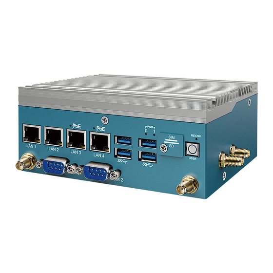
2.2 Front Panel I/O & Functions 2.2.1 Functions of EAC-2000 In Vecow EAC-2000 series, Most of the I/O connectors are located on the front panels. Most of the general connections to computer devices, such as USB, LAN, Force Recovery button, User-Define Button, indicators are placed on the front panel. - Page 18 2.2.1.3 Nano SIM The external Nano SIM card offers wireless communication capability to the system. ©Vecow EAC-2000 User Manual GETTING TO KNOW YOUR EAC-2000/2100...
- Page 19 The external Micro SD card provides additional storage expansion. It is located behind the cover-plate on the front panel. 2.2.1.5 Two user Programmable LEDs There are two Programmable LEDs, user can define the state of the LED by himself. ©Vecow EAC-2000 User Manual GETTING TO KNOW YOUR EAC-2000/2100...
- Page 20 There are 4 USB 3.0 connections available supporting up to 5Gb per second data rate in the front panel of EAC-2000. It is also compliant with the requirements of Speed (SS), High Speed (HS), Full Speed (FS) and Low Speed (LS).
- Page 21 Solid Right Orange Green Orange Twinkling Twinkling Twinkling Left Yellow Yellow Yellow Yellow POE_LED1 POE_LED2 POE LED LED Color POE Status POE_LED1 Solid Orange POE ON POE_LED2 Solid Orange POE ON ©Vecow EAC-2000 User Manual GETTING TO KNOW YOUR EAC-2000/2100...
- Page 22 2.2.1.8 LAN 1, LAN 2 10/100/1000 Mbps Ethernet Port There are two 8-pin RJ-45 jacks supporting 10/100/1000 Mbps Ethernet connections on the front panel of EAC-2000. LAN 1 and LAN 2 are powered by ® Intel I350 Ethernet engine. ®...
- Page 23 2.2.1.9 PWR & Status LED Indicators LED Color System Status Orange (PWR LED) +V3.3 Power Ready 2.2.2 Functions of EAC-2100 On the front panel, there are two additional COM Port connectors in EAC-2100 Series. ©Vecow EAC-2000 User Manual GETTING TO KNOW YOUR EAC-2000/2100...
- Page 24 The pin assignments are listed in the following table : COM Port Pin No. RS-232 RS-485 (3-wire) ----------- DATA- DATA+ ----------- ----------- ----------- 1, 2 ----------- ----------- ----------- ----------- ----------- ----------- ----------- ----------- ©Vecow EAC-2000 User Manual GETTING TO KNOW YOUR EAC-2000/2100...
-
Page 25: Rear Panel I/O & Functions
The DC-in connector, COM ports, Micro USB ports, and Digital Display are on the rear panel of the EAC-2000. 2.3.1.1 Power Terminal Block EAC-2000 supports 9V to 50V DC wide range power input by terminal block in the rear side. Pin No. - Page 26 JCOM1 COM 2 JCOM2 COM 1 & COM 2 MB connector pin out : Pin No. Signal Name Pin No. Signal Name ----------- ----------- ----------- JCOM1 JCOM2 RXD/D+ ----------- JCOM2 JCOM1 ©Vecow EAC-2000 User Manual GETTING TO KNOW YOUR EAC-2000/2100...
- Page 27 USB_DATA+ 2.3.1.4 System Recovery Port The EAC-2000 USB Recovery mode provides an alternate boot device (USB). In this mode, the system is connected to a host system and boots over USB. This is used when a new image needs to be flashed. USB0 must be available to use as USB Device for USB Recovery Mode.
- Page 28 CAN Bus Connector Pin Out : CAN Port MB Connnector JCAN1 JCAN1 MB connector pin out : CAN Port Pin No. Description Pin No. Description +3.3V CAN_L JCAN1 (CAN) CAN_H JCAN1 ©Vecow EAC-2000 User Manual GETTING TO KNOW YOUR EAC-2000/2100...
- Page 29 EAC-2100 through a single coax cable. Using GMSL2 (Gigabit Multimedia Serial Link) connections, the cameras are connected to a two-port deserializer. The output of the deserializer is MIPI CSI-2. ©Vecow EAC-2000 User Manual GETTING TO KNOW YOUR EAC-2000/2100...
-
Page 30: Main Board Connector & Jumper Locations
2.4.1 TOP View of MB JCOM2 JCOM1 JP10 JSPI2 JSPI1 M2E_CN1 JAUDIO JCAN1 BAT1 M2B_CN1 M2M_CN1 LAN4 LAN3 LAN2 LAN1 2.4.2 BOT View of MB DIMM1 POWER_LED POE_LED1 POE_LED2 LED2 LED1 CN10 ©Vecow EAC-2000 User Manual GETTING TO KNOW YOUR EAC-2000/2100... - Page 31 M2E_CN1 M.2 KEY E : USB 2.0/PCIe x1 M.2 key E connector is suitable for applications that use wireless connectivity including Wi-Fi, Bluetooth, NFC of GNSS. Module card types include 2230. ©Vecow EAC-2000 User Manual GETTING TO KNOW YOUR EAC-2000/2100...
- Page 32 Pin No. Signal Name Pin No. Signal Name +V3.3_AUX +V3.3_AUX PEWAKE I2C_ALERT# I2C_CLK I2C_DATA PCIE_WAKE# PCIE_CLK_REQ0# PLTRST# SUS_CLK PCIE_100M_CLK__N PCIE_100M_CLK__P PCIE_RX_N PCIE_RX_P PCIE_TX_N PCIE_TX_P Mechanical Key USB- LED1# USB+ +V3.3_AUX +V3.3_AUX ©Vecow EAC-2000 User Manual GETTING TO KNOW YOUR EAC-2000/2100...
- Page 33 2.4.5 M2B_CN1 : M.2 KEY-B M.2 key B Connector (3042/3052, PCIe Gen2x1, USB 3.0, USB 2.0) M2B_CN1 2.4.6 M2M_CN1 : M.2 KEY-M M.2 key M Connector (2280, PCIe Gen3x1) M2M_CN1 ©Vecow EAC-2000 User Manual GETTING TO KNOW YOUR EAC-2000/2100...
- Page 34 2.4.7 CN5 : Board to Board Connector for Camera Board (EAC-2000-CB) Camera connector; enables use of CSI cameras. The EAC-2100 works with Sony IMX390 camera modules, including oToBrite oToCAM264ISP-L61M camera module. Definition Definition Definition Definition CAM0_MCLK P12V 28 CAM_I2C_SCL CAM1_MCLK...
- Page 35 Description Pin No. Description OUTP_L OUTN_L OUTP_R OUTN_R 2.4.9 JCAN1 : CAN BUS Connector EAC-2000 has a single controlled area network (CAN) interface to the JCAN1 connector. JCAN1 JCAN1 MB connector pin out : Pin No. Description Pin No. Description +3.3V...
- Page 36 2.4.10 JSPI1, JSPI2 : SPI/I2C Signal Connector There are two SPI+I2C headers, it offered SPI Bus and I2C Bus, in EAC-2000 series. JSPI2 JSPI1 Pin No. JSPI1 Definition Pin No. JSPI2 Definition +3.3V +3.3V SPI0_MOSI SPI1_MOSI SPI0_MISO SPI1_MISO SPI0_CS0 SPI1_CS0...
- Page 37 2.4.12 DIMM1 : SO-DIMM connector only for Jetson Xavier NX module DIMM1 ©Vecow EAC-2000 User Manual GETTING TO KNOW YOUR EAC-2000/2100...
-
Page 38: Main Board Jumper Settings
2.5 Main Board Jumper Settings 2.5.1 Board Top View of EAC-2000 Main Board with Jumper The figure below is the top view of EAC-2000 main board which is the main board. It shows the location of the jumpers. JP10 You may configure your card to match the needs of your application by setting jumpers. - Page 39 Function Auto Power ON Enable (Default) Auto Power ON Disable 2.5.3 JP8 : POE Power On Voltage Select Setting Function POE Power On Voltage 12V (Default) POE Power On Voltage 3.3V ©Vecow EAC-2000 User Manual GETTING TO KNOW YOUR EAC-2000/2100...
- Page 40 COM RS485 mode function. Jumper Setting Function RS485 Mode Terminal resistance OFF (Default) (COM1) RS485 Mode Terminal resistance ON RS485 Mode Terminal resistance OFF (Default) JP10 (COM1) RS485 Mode Terminal resistance ON ©Vecow EAC-2000 User Manual GETTING TO KNOW YOUR EAC-2000/2100...
-
Page 41: Expansion Board Connectors & Jumper Locations
2.6 Expansion Board Connectors & Jumper Locations 2.6.1 TOP View of Daughter Board JP4 JP5 JP7 JP8 2.6.2 BOT View of Daughter Board ©Vecow EAC-2000 User Manual GETTING TO KNOW YOUR EAC-2000/2100... - Page 42 FAKRA coax cables. CN2, CN3 and CN4, CN5 are connected to each two-port deserializer. Part location Definition Coax Serial-Data Input/Output 1 Coax Serial-Data Input/Output 2 Coax Serial-Data Input/Output 3 Coax Serial-Data Input/Output 4 ©Vecow EAC-2000 User Manual GETTING TO KNOW YOUR EAC-2000/2100...
- Page 43 The GMSL2 forward link has a fixed link rate of 3Gbps or 6Gbps. JP1 and JP3 Pin define : Pin No. Definition GMSL2_6G_2 CFG1_2 GMSL2_3G_2 JP1 and JP3 Jumper setting : Jumper pin GMSL 2 rate *1-2 6 Gbps (Default) 3 Gbps ©Vecow EAC-2000 User Manual GETTING TO KNOW YOUR EAC-2000/2100...
- Page 44 VDD12V The voltage is fixed at +12V when POC VPOC_IN1 output from overcurrent Protection IC and will adjusted at +12V or +5V when POC VDD5V not output from overcurrent Protection IC. ©Vecow EAC-2000 User Manual GETTING TO KNOW YOUR EAC-2000/2100...
- Page 45 +12V (Default) VPOC_IN2 The voltage is fixed at +12V when POC output from overcurrent Protection IC and VDD5V will adjusted at +12V or +5V when POC not output from overcurrent Protection IC. ©Vecow EAC-2000 User Manual GETTING TO KNOW YOUR EAC-2000/2100...
- Page 46 +12V MFP0_2 CSI2_D1_P MFP5_2 CSI2_D1_N MFP6_2 CSI2_CLK_P CSI3_D1_P CSI2_CLK_N CSI3_D1_N CSI2_D0_P CSI3_D0_P CSI2_D0_N CSI3_D0_N CAM0_MCLK CAM_I2C_SCL CAM0_PWDN CAM_I2C_SDA MFP0_1 CSI0_D1_P MFP5_1 CSI0_D1_N MFP6_1 CSI0_CLK_P CSI1_D1_P CSI0_CLK_N CSI1_D1_N CSI0_D0_P CSI1_D0_P CSI0_D0_N CSI1_D0_N ©Vecow EAC-2000 User Manual GETTING TO KNOW YOUR EAC-2000/2100...
-
Page 47: Chapter 3 System Setup
SYSTEM SETUP 3.1 How to Open Your EAC-2000/2100 Remove four F-M3x4L screws and pick up bottom cover. ©Vecow EAC-2000 User Manual SYSTEM SETUP... -
Page 48: Installing Nano Sim Card
3.2 Installing Nano SIM Card Step 1 Remove one F-M3x4L screw on SD/SIM cover. Step 2 Inserting SIM card, make sure the system power is not plugged. ©Vecow EAC-2000 User Manual SYSTEM SETUP... -
Page 49: Installing Micro Sd Card
3.3 Installing Micro SD Card Step 1 Remove one F-M3x4L screw on SD/SIM cover. Step 2 Inserting SD card. ©Vecow EAC-2000 User Manual SYSTEM SETUP... -
Page 50: Installing
3.4.1 M.2 Key B (3042), M.2 Key E (2230), M.2 Key M (2280) Install M.2 card into the M.2 slot and fasten PHILLPIS-M3x4L screw. Key M 2280 Key B 3042 Key E 2230 3.4.2 M.2 Key B (3052) 3.4.2-1 Change the stud position. ©Vecow EAC-2000 User Manual SYSTEM SETUP... - Page 51 3.4.2-2 Install M.2 card into the M.2 slot and fasten PHILLPIS-M3x4L screw. ©Vecow EAC-2000 User Manual SYSTEM SETUP...
-
Page 52: Installing Antenna Cable
3.5 Installing Antenna Cable Step 1 Remove the rubber corks on the panel. Step 2 Put antenna cable connector into the hole on panel. Step 3 Fasten washer on the antenna cable connector. ©Vecow EAC-2000 User Manual SYSTEM SETUP... -
Page 53: Mounting Your Eac-2000/2100
3.6 Mounting Your EAC-2000/2100 Wall Mount Install wall mount bracket then fasten four pcs F-M3x4L screws. DIN Rail Mount Install din rail kit then fasten screws. ©Vecow EAC-2000 User Manual SYSTEM SETUP... -
Page 54: Chapter 4 Software Setup
SOFTWARE SETUP 4.1 Peripheral Interface Guide 4.1.1 Serial Port 1. EAC-2000/2100 have two RS-232/485 serial port for connection. To switch the type of your serial ports, you can issue the following commands : Set COM1 to 232 Mode : $ sudo setcom 1 232... - Page 55 4.1.3 I2S EAC-2000/2100 have an internal I2S connector, issue the following commands before you start to play audio by I2S : $ amixer -c 1 cset name="I2S1 Mux" "I2S5" Turn on the I2S audio : $ sudo set_audio 1 Turn off the I2S audio :...
-
Page 56: Determine Available Drive Space
To determine the amount of available drive space, you can issue the following commands : $ sudo df -h 4.3 Install the CUDA package 1. To install the CUDA package on EAC-2000/2100, you can issue the following commands : $ sudo apt update $ sudo apt install nvidia-cuda 4.4 Flash image to Your EAC-2000/2100... - Page 57 4.4.2 Connect EAC-2000/2100 to the host computer Step.1 Connect the Micro USB cable to the "Flash" Port on EAC-2000/2100 and the other end to an available USB port on the host PC. Step.2 Press and hold the "RECOV" button. and connect the power adapter. Continue to hold the "RECOV" button for two seconds, and release.
- Page 58 4.4.3 Flash image to the EAC-2000/2100 Step.1 Open a terminal on host PC, then access the package folder you extracted in the 4.4.1 section. Step.2 Issue the following command to flash the image : $ sudo start_update.sh. Step.3 Once the process finished, you should see the following log : ©Vecow EAC-2000 User Manual...
-
Page 59: Appendix A : Gmsl Camera Guide (Eac-2100 Only)
To initialize the GMSL camera, you can access the following path to find the camera scripts : $ cd /usr/src/tools/gmsl_camera/ "init.sh" includes camera bring up script and camera driver installation. "preview_imx390ISP_example.sh" includes the command to open the camera with GStreamer. ©Vecow EAC-2000 User Manual APPENDIX A : GMSL Camera Guide (EAC-2100 only) -
Page 60: Appendix B : Power Consumption
M.2 KEY E Intel 9260NGW LAN 1 1.0 Gbps LAN 2 1.0 Gbps LAN 3 1.0 Gbps LAN 4 1.0 Gbps Graphics Output HDMI Power Plan Default Power Source Chroma 62006P-100-25 Test Program Stress-ng Test ©Vecow EAC-2000 User Manual Appendix B... - Page 61 CPU Run BurnInTest/Stress-ng Test Input Current Consumption Current Consumption 1.678A 15.10W 2.181A 19.63W 1.267A 15.20W 1.662A 19.94W NVIDIA Jetson Xavier NX 0.664A 15.94W 0.865A 20.76W System-On-Module 0.462A 16.63W 0.602A 21.67W 0.344A 17.20W 0.442A 22.10W ©Vecow EAC-2000 User Manual Appendix B...
-
Page 62: Appendix C : Supported Expansion Module List
QZSS (Optional) 5G sub-6GHz M.2 KEY B Quectel RM500Q-AE Worldwide 5G and LTE-A coverage GPS/GLONASS/BeiDou (Compass)/Galileo C.2 Supported Wi-Fi/Bluetooth List Type Model Support Standard IEEE 802.11 a/b/g/n/ac (2x2) M.2 KEY E Intel AX210 BT 5.2 ©Vecow EAC-2000 User Manual Appendix C... - Page 63 No part of this publication may be reproduced in any form or by any means, electric, photocopying, or recording, without prior authorization from the publisher. The rights of all the brand names, product names, and trademarks belong to their respective owners. © Vecow Co., Ltd. 2021. All rights reserved.
Need help?
Do you have a question about the EAC-2000 and is the answer not in the manual?
Questions and answers