
Related Manuals for Vecow PBC-1000


Summary of Contents for Vecow PBC-1000
- Page 1 USER USER PBC-1000 Manual Manual Intel Atom ® x6211E (Elkhart Lake) Fanless Embedded System, Ultra-Compact, Rugged, -40°C to 70°C Operation Temperature 1.0.0 Edition 20220616...
- Page 2 Record of Revision Version Date Page Description Remark 1.00 2022/05/20 Official Release ©Vecow PBC-1000 User Manual...
- Page 3 This manual is released by Vecow Co., Ltd. for reference purpose only. All product offerings and specifications are subject to change without prior notice. It does not represent commitment of Vecow Co., Ltd. Vecow shall not be liable for direct, indirect, special, incidental, or consequential damages arising out of the use of the product or documentation or any infringements upon the rights of third parties, which may result from such use.
- Page 4 60W, 12V, 90V AC to 264V AC Power Adapter with 2-pin PWA-60W-12V Terminal Block DIN-RAIL DIN Rail Mounting Kit 5G Module 5G Module with Antenna 4G Module 4G/GPS Module with Antenna WiFi & Bluetooth WiFi & Bluetooth Module with Antenna ©Vecow PBC-1000 User Manual...
-
Page 5: Table Of Contents
2.3 Rear Panel I/O & Functions 2.4 Main Board Expansion Connectors 2.5 Main Board Jumper Settings CHAPTER 3 SETUP 3.1 How to Open Your PBC-1000 3.2 Installing DDR4 SO-DIMM Modules 3.3 Installing SIM Card 3.4 Installing SSD/HDD 3.5 Installing M.2 3.6 Installing Antenna cable... - Page 6 4.6 Boot Function 4.7 Save & Exit APPENDIX A : GPIO Guide APPENDIX B : Software Functions APPENDIX C : Power Consumption APPENDIX D : Supported Memory & Storage List APPENDIX E : Driver install (Unknown Device ) ©Vecow PBC-1000 User Manual...
-
Page 7: Chapter 1 General Introduction
GENERAL INTRODUCTION 1.1 Overview Vecow PBC-1000 is an Ultra-Compact Fanless Embedded Box PC. Powered by ® Intel Atom x6000E Series processor, Vecow PBC-1000 brings power-efficient, enhanced graphics performance and flexibility capabilities to empower the edge applications such as Intelligent Control, Energy Management, M2M, In-Vehicle Infotainment, factory Automation, and any AIoT/Industry 4.0 applications. -
Page 8: Features
• 2 GigE LAN, 2 USB 3.0, 2 COM, M.2 Key B, M.2 Key E • SIM Socket for WiFi/5G/4G/LTE/GPRS/UMTS • Optional VHub AIoT Solution Service supports OpenVINO based AI accelerator and advanced Edge AI applications ©Vecow PBC-1000 User Manual GENERAL INTRODUCTION... -
Page 9: Product Specification
1.3 Product Specification 1.3.1 Specifications of PBC-1000 System ® Processor Intel Atom x6211E Processor (Elkhart Lake) BIOS IT8786E Memory 1 DDR4 3200MHz SO-DIMM, up to 32GB Windows 10, Linux Graphics ® ® Processor Intel UHD Graphics for 10th Gen Intel... -
Page 10: Mechanical Dimension
• IEC 60068-2-64 • SSD : 5Grms, 5Hz to 500Hz, 3 Axis CE, FCC, EN50155, EN50121-3-2 1.4 Mechanical Dimension 159.2 6.27 143.6 5.65 Unit:mm(inch) 126.0 4.96 4.5 0.18 A Detail 78.5 3.09 Unit : mm (inch) ©Vecow PBC-1000 User Manual GENERAL INTRODUCTION... -
Page 11: Getting To Know Your Pbc-1000
GETTING TO KNOW YOUR PBC-1000 2.1 Packing List Item Description PBC-1000 Embedded System Driver/User Manual DVD Item Description Picture Use for PHILLPIS 53-2426204-80B M3*4L Wall mount M3x4L 53-2466204-30B Bracket/HDD Terminal block DC-IN 51-2411R02-S1C 2-pin (5.0mm) Wall Mount Mount 62-01P0727-B00 M.2 Bracket... -
Page 12: Front Panel I/O & Functions
2.2 Front Panel I/O & Functions In Vecow’s PBC-1000 series family, all I/O connectors are located on the front panel. Most of the general connections to the computer device, such as DC power input, SIM slot, Display port, USB3.2 and LAN Jack are placed on the front panel. - Page 13 2.2.3 Power Button The power button is a non-latched switch. To power on PBC-1000, press the power button.To power off PBC-1000, you can either command shutdown by OS operation or simply press the power button. If system error appears, press and hold the power button for four seconds to shut down the machine directly.Please do note that a four-...
- Page 14 There are 2 USB 3.2 Gen1 connections available supporting up to 5GB per second data rate in the front side of PBC-1000. It is also compliant with the requirements of Super Speed (SS), high speed (HS), full speed (FS) and low speed (LS).
- Page 15 2.2.8 Nano SIM Card Socket for M.2 key B Slot The Nano SIM card socket is support Push-Push type. Please make sure to unplug the system power before inserting the Nano SIM card. ©Vecow PBC-1000 User Manual GETTING TO KNOW YOUR PBC-1000...
-
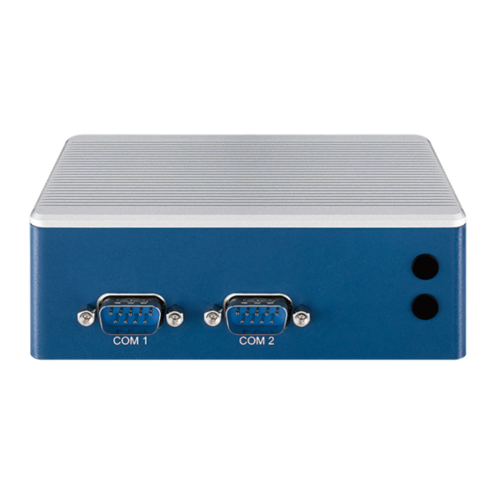
Page 16: Rear Panel I/O & Functions
RS-422 or RS-485, you can find the setting in BIOS.The pin assignments are listed in the following table: BIOS Setting Function RS-232 RS-422 (5-wire) COM1 RS-485 RS-485 w/z auto-flow control ©Vecow PBC-1000 User Manual GETTING TO KNOW YOUR PBC-1000... -
Page 17: Main Board Expansion Connectors
2.4 Main Board Expansion Connectors 2.4.1 PBC-1000 Main Board Top Side View JRESET ESD1 LAN2 LAN1 LAN2 LAN1 P_V12A1 R1270 R623 FUSE1 R1269 M167 R1170 C1682 C245 C243 C247 GPO1 GPO2 R101 R1271 P_AUX1 R100 R103 R102 R104 R105 R106... - Page 18 2.4.3 BAT2 : Battery The PBC-1000 real-time clock is powered by a lithium battery. It is equipped with Panasonic BR2032 190mAh lithium battery. It is recommended that you not replace the lithium battery on your own, but if the battery needs to be changed, please contact the Vecow RMA service team.
- Page 19 M2E_CN1 are listed in the following table : Pin No. Signal Name Pin No. Signal Name 3.3V 3.3V ALERT# (O)(0/3.3V) 12C_CLK (I)(0/3.3V) 12C_DATA (I/O)(0/3.3V) PEWAKE0# (I/O)(0/3.3V) PERST0# (I)(0/3.3V) CLKREQ0# (I/O)(0/3.3V) REFCLKn0 REFCLKp0 ©Vecow PBC-1000 User Manual GETTING TO KNOW YOUR PBC-1000...
- Page 20 PERn0 PERp0 PETn0 PETp0 Module Key Module Key Module Key Module Key Module Key Module Key Module Key Module Key LED2# (O)(od) LED1# (O)(od) 3.3V USB_D- 3.3V USB_D+ ©Vecow PBC-1000 User Manual GETTING TO KNOW YOUR PBC-1000...
- Page 21 C200 R342 R343 C203 SATA1 R348 R349 R350 C204 C207 C208 C209 R351 C210 HDD_PWR_J1 CONFIG_1 JSTATUS JHDD R352 R353 R354 C211 SIM DETECT PEWAKE# REFCLKp CLKREQ# REFCLKn PERST# PETp0/SATA-A+ PETn0/SATA-A- ©Vecow PBC-1000 User Manual GETTING TO KNOW YOUR PBC-1000...
- Page 22 UIM-PWR PETp1/USB3.1-TX+ UIM-DATA PETp1/USB3.1-TX- UIM-CLK UIM-RESET PETp1/USB3.1-RX+ PETp1/USB3.1-RX- Module Key Module Key Module Key Module Key Module Key Module Key Module Key Module Key LED_1# W_DISABLE1 USB- FULL_CARD_PWR_OFF/ON USB+ 3.3V 3.3V ©Vecow PBC-1000 User Manual GETTING TO KNOW YOUR PBC-1000...
- Page 23 R352 R353 R354 C211 RS-422 RS-485 Serial Port RS-232 Number (5-wire) (3-wire) TXD- DATA- TXD+ DATA+ RXD+ -------- RXD- -------- (RS232 only) -------- -------- (Full) -------- -------- -------- -------- -------- -------- ©Vecow PBC-1000 User Manual GETTING TO KNOW YOUR PBC-1000...
- Page 24 R336 FB5 C190 R337 R338 R339 C191 R334 C193 C198 C199 C200 R342 R343 C203 SATA1 R348 R349 R350 C204 C207 C208 C209 R351 C210 HDD_PWR_J1 JSTATUS JHDD R352 R353 R354 C211 ©Vecow PBC-1000 User Manual GETTING TO KNOW YOUR PBC-1000...
- Page 25 R352 R353 R354 C211 The PBC-1000 series is also equipped with one SATA power connector. It supports 5V (Up to 1.2A) a to the SSD only. The pin assignments of HDD_PWR_J1 is listed in the following table Pin No. Definition Pin No.
- Page 26 These pin header can be used as a backup for following functions, hard drive LED indicator, reset button, power LED indicator, The pin assignments are listed in the following table : Pin No. Pin No. Definition FP_PWR_BTN_IN JRESET PWR_LED_P JSTATUS PWR_LED_N HDD_LED_P JHDD HDD_LED_N ©Vecow PBC-1000 User Manual GETTING TO KNOW YOUR PBC-1000...
- Page 27 R343 C203 SATA1 R348 R349 R350 C204 C207 C208 C209 R351 C210 HDD_PWR_J1 JSTATUS JHDD R352 R353 R354 C211 Pin No. Definition SIO_GPIO1 SIO_GPIO2 SIO_GPIO3 SIO_GPIO4 SIO_GPIO5 SIO_GPIO6 SIO_GPIO7 SIO_GPIO8 +3.3V ©Vecow PBC-1000 User Manual GETTING TO KNOW YOUR PBC-1000...
-
Page 28: Main Board Jumper Settings
2.5 Main Board Jumper Settings 2.5.1 Top View of PBC-1000 Main Board With Jumper Location The figure below is the top view of the EPBC-1000 main board. It shows the location of the jumpers. JRESET ESD1 LAN2 LAN1 P_V12A1 R1270... - Page 29 R336 FB5 C190 R337 R338 R339 R334 C191 C193 C198 C199 C200 R342 R343 C203 SATA1 R348 R349 R350 C204 C207 C208 C209 R351 C210 HDD_PWR_J1 JSTATUS JHDD R352 R353 R354 C211 ©Vecow PBC-1000 User Manual GETTING TO KNOW YOUR PBC-1000...
-
Page 30: Chapter 3 Setup
SETUP 3.1 How to Open Your PBC-1000 Step 1 Remove the Screw indicated and separate Cover from the enclosure. Step 1 Remove the bottom cover. ©Vecow PBC-1000 User Manual SETUP... -
Page 31: Installing Ddr4 So-Dimm Modules
Step 1 Remove four #6-32 Screws, two M3 Screws indicated and separate Cover from the enclosure. Step 2 Remove the screws indicated and separate the heat-sink from the PCB. Step 3 Install DDR4 RAM module into SO-DIMM socket. ©Vecow PBC-1000 User Manual SETUP... -
Page 32: Installing Sim Card
Step 4 Finished. 3.3 Installing SIM Card Step 1 Install SIM card into the SIM card slot. 3.4 Installing SSD/HDD Step 1 Remove the bottom cover. ©Vecow PBC-1000 User Manual SETUP... - Page 33 Step 2 Fasten four Screws indicated. ©Vecow PBC-1000 User Manual SETUP...
-
Page 34: Installing
3.5.2 Key B 2280 Step 1 Install M.2 into the M.2 slot and fasten M3 screw indicated. 3.5.3 Key B 3042 Step 1 Install M.2 with M.2 Tray into the M.2 slot and fasten M3 screw indicated. ©Vecow PBC-1000 User Manual SETUP... -
Page 35: Installing Antenna Cable
Step 1 Install M.2 with M.2 Tray into the M.2 slot and fasten M3 screw indicated. 3.6 Installing Antenna cable Step 1 Check antenna cable and washers. Step 2 Install antenna cable and then fasten washer and nut. ©Vecow PBC-1000 User Manual SETUP... -
Page 36: Mounting Your Pbc-1000
3.7 Mounting Your PBC-1000 3.7.1 Install wall mount to PBC-1000, Install four F head M3x4L screws 3.7.2 Install DIN Rail Kit to PBC-1000 Wall mount, Install four M3x4L screws ©Vecow PBC-1000 User Manual SETUP... - Page 37 Figure 4-1 : Entering Setup Screen BIOS provides an interface for users to check and change system configuration. The BIOS setup program is accessed by pressing the <Del> key when POST display output is shown. ©Vecow PBC-1000 User Manual BIOS SETUP...
- Page 38 System Date Set the date. Use Tab to switch between date elements. System Time Set the time. Use Tab to switch between time elements. ©Vecow PBC-1000 User Manual BIOS SETUP...
- Page 39 4.3 Advanced Functions Figure 4-3 : BIOS Advanced menu Select advanced tab to enter advanced BIOS setup options such as CPU configuration, USB configuration, and Network Stack configuration. 4.3.1 CPU Configuration Figure 4-3-1 : CPU Configuration ©Vecow PBC-1000 User Manual BIOS SETUP...
- Page 40 Figure 4-3-2-1 : CPU - Power Management Control Boot performance mode Select the performance state that the BIOS will set starting from reset vector. Intel(R) SpeedStep(tm) Allows more than two frequency ranges to be supported. ©Vecow PBC-1000 User Manual BIOS SETUP...
- Page 41 Disable Turbo GT frequency Enabled: Disables Turbo GT frequency. Disabled: GT frequency is not limited. 4.3.3 PCH-FW Configuration Figure 4-3-3 : PCH-FW Configuration ME State CWhen Disabled ME will be put into ME Temporarily Disabled Mode. ©Vecow PBC-1000 User Manual BIOS SETUP...
- Page 42 Gfx LLC allocation to minimize impact of Gfx workload on LLC. 4.3.5 Trusted Computing Figure 4-3-5 : Trusted Computing Control the TPM device status and display related information if TPM chip is present. ©Vecow PBC-1000 User Manual BIOS SETUP...
- Page 43 4.3.8 IT8786 Super IO Configuration Figure 4-3-8 : IT8786 Super IO Configuration Serial Port 1 Configuration Set Parameters of Serial Port 1 (COMA). Serial Port 2 Configuration Set Parameters of Serial Port 2 (COMB). ©Vecow PBC-1000 User Manual BIOS SETUP...
- Page 44 Both computers should have the same or compatible settings. 4.3.11 Acoustic Management Configuration Figure 4-3-11 : Acoustic Management Configuration Acoustic Management Configuration Option to Enable or Disable Automatic Acoustic Management. ©Vecow PBC-1000 User Manual BIOS SETUP...
- Page 45 DISABLE option will keep USB devices available only for EFI applications. XHCI Hand-off This is a workaround for OSes without XHCI hand-off support. The XHCI ownership change should be claimed by XHCI driver. ©Vecow PBC-1000 User Manual BIOS SETUP...
- Page 46 Wait time in seconds to press ESC key to abort the PXE boot. Use either +/- or numeric keys to set the value. Media detect count Number of times the presence of media will be checked. Use either +/- or numeric keys to set the value. ©Vecow PBC-1000 User Manual BIOS SETUP...
- Page 47 4.4.1 System Agent (SA) Configuration Figure 4-4-1 : System Agent (SA) Configuration VT-d VT-d capability. Above 4GB MMIO BIOS assignment Enable/Disable above 4GB MemoryMappedIO BIOS assignment. This is enabled automatically when Aperture Size is set to 2048MB. ©Vecow PBC-1000 User Manual BIOS SETUP...
- Page 48 Enabling Error Injection allows attackers who have access to the Host Operating System to inject IBECC errors that can cause unintended memory corruption and enable the leak of security data in the BIOS stolen memory regions. ©Vecow PBC-1000 User Manual BIOS SETUP...
- Page 49 Select DVMT 5.0 Pre-Allocated (Fixed) Graphics Memory size used by the Internal Graphics Device. DVMT Total Gfx Mem Select DVMT5.0 Total Graphic Memory size used by the Internal Graphics Device. PM Support Enable/Disable PM Support. ©Vecow PBC-1000 User Manual BIOS SETUP...
- Page 50 2 - ~ Power Management Events 3 - PCIe Advanced Error Reporting control 4 - PCIe Capability Structure control 5 - Latency Tolerance Reporting control PCI Express device settings BIOS options for PCI Express device setting. ©Vecow PBC-1000 User Manual BIOS SETUP...
- Page 51 Otherwise all drives spin up at boot. SATA Device Type Identify the SATA port is connected to Solid State Drive or Hard Disk Drive. ©Vecow PBC-1000 User Manual BIOS SETUP...
- Page 52 Force unlock on all GPIO pads If Enabled BIOS will force all GPIO pads to be in unlocked state. 4.5 Security Function Figure 4-5 : BIOS Security Menu Administrator Password Set Administrator Password. User Password Set User Password. ©Vecow PBC-1000 User Manual BIOS SETUP...
- Page 53 Secure Boot mode options: Standard or Custom. In Custom mode, Secure Boot Policy variables can be configured by a physically present user without full authentication. Key Management Enables expert users to modify Secure Boot Policy variables without full authentication. ©Vecow PBC-1000 User Manual Appendix 3...
- Page 54 Number of seconds to wait for setup activation key. 65535(0xFFFF) means indefinite waiting. Bootup NumLock State Select the keyboard NumLock state. Quiet Boot Enables or disables Quiet Boot option. Boot Option #x Sets the system boot order. ©Vecow PBC-1000 User Manual Appendix 3...
- Page 55 Restore Defaults Restore/Load Default values for all the setup options. Save as User Defaults Save the changes done so far as User Defaults. Restore User Defaults Restore the User Defaults to all the setup options. ©Vecow PBC-1000 User Manual Appendix 3...
- Page 56 C207 C208 C209 R351 C210 HDD_PWR_J1 JSTATUS JHDD R352 R353 R354 C211 GPIO1 Pin No. GPIO Definition GPIO 0 GPIO 1 GPIO 2 GPIO 3 GPIO 4 GPIO 5 GPIO 6 GPIO 7 +VDIO ©Vecow PBC-1000 User Manual Appendix A...
- Page 57 Sample folders include sample program, driver library, and API library for Windows/Linux Source folders include sample program source code that compile on Visual Studio 2008/ ubuntu18.04. A.3 Sample Execute demo tool. Windows Linux Vecow_DIO Vecow_DIO_loopback ©Vecow PBC-1000 User Manual Appendix A...
- Page 58 Vecow_WDT ©Vecow PBC-1000 User Manual Appendix A...
- Page 59 APPENDIX B : Software Functions B.1 Driver API Guide In Header folder, Vecow.h and VecowLinux.h contain usabled API for Windows/ Linux. BOOL initial_SIO(BYTE Isolate_Type, BYTE DIO_NPN) Initial machine for IO and watch dogtimer. Isolate_Type: DIO type. 1: Isolated DIO; 0: Non-Isolated DIO(GPIO).
- Page 60 WDT: watchdog timer setup Unit: second. (Range: 0 ~ 65535 sec, 1093 ~ 65535 min (=65580 ~ 3932100 sec)) Return: TRUE (1): Success; FALSE (0): Fail (Initial error, or call by pointer error, or hardware problem) ©Vecow PBC-1000 User Manual Appendix B...
- Page 61 0: RS232 mode; 1: RS422-5Wire mode. 2: RS422-9Wire mode; 4: RS485 mode. 4: Loopback mode. G.term: Termination enable for RS422/RS485 mode. 1: Enable; 0: Disable. Return: TRUE (1): Success; FALSE (0): Fail (Initial error or hardware problem) ©Vecow PBC-1000 User Manual Appendix B...
- Page 62 USB Mouse HP G1K28AA SATA 0 Apacer SATA AP120GAS340XC SATA 1 Kingston SA400MB/480GB LAN 1 (RTL8119I) 1.0 Gbps LAN 2 (RTL8119I) 1.0 Gbps Graphics Output Power Plan Balance (Windows10 Power plan) Power Source : Chroma 62006P-100-25 ©Vecow PBC-1000 User Manual Appendix C...
- Page 63 Power on and boot to Win10 64bit Run 100% CPU Run 100% CPU Power usage without 2D usage with 3D Input Current Consumption Current Consumption ® Intel Atom 0.889A 10.67W 0.940A 11.28W x6211E ©Vecow PBC-1000 User Manual Appendix C...
- Page 64 Test Temp. Brand Info (Celsius) innodisk 16G DDR4-2400 SO-DIMM M4D0-AGS1Q5SJ-H03 25ºC innodisk 4G DDR4-2666 SO-DIMM M4S0-4GSSNCIK-H03 25ºC MemxPro 16G DDR4-2666 SO-DIMM D4S-AG26H1G8W2 25ºC SL-Link 32GB DDR4-3200 SODIMM J4BGSH2G8TMFC 25ºC Smart 16GB DDR4-3200 SODIMM ST2046SO410825-SE 25ºC ©Vecow PBC-1000 User Manual Appendix D...
- Page 65 SATA SSD Intel SSD E 5400s SSDSC2KR120H6 120GB MEMXPRO M3A MI3MA1212802WN 128GB FORESEE S903S128G 128GB FORESEE S903S256G 256GB LITE-ON K8-L1256 256GB LITE-ON K8-L1512 512GB ** If more help is needed, please contact Vecow Technical Support.** ©Vecow PBC-1000 User Manual Appendix D...
- Page 66 APPENDIX E : Driver install (Unknown Device ) Right-click file, select Extract All… Click Extract ©Vecow PBC-1000 User Manual Appendix E...
- Page 67 Right-click start select Device Manager Right-click Unknown device select Update driver ©Vecow PBC-1000 User Manual Appendix E...
- Page 68 Select Browse my computer for drivers Click Browse ©Vecow PBC-1000 User Manual Appendix E...
- Page 69 Select decompressed file Click OK Click Next ©Vecow PBC-1000 User Manual Appendix E...
- Page 70 Update Unknown Driver successfully ©Vecow PBC-1000 User Manual Appendix E...
- Page 71 No part of this publication may be reproduced in any form or by any means, electric, photocopying, or recording, without prior authorization from the publisher. The rights of all the brand names, product names, and trademarks belong to their respective owners. © Vecow Co., Ltd. 2022. All rights reserved. ©Vecow PBC-1000 User Manual Appendix E...
Need help?
Do you have a question about the PBC-1000 and is the answer not in the manual?
Questions and answers