
Subscribe to Our Youtube Channel
Related Manuals for Vecow ECX-2200 PEG


Summary of Contents for Vecow ECX-2200 PEG
- Page 1 USER USER ECX-2200/2100 PEG Manual Manual 10th Gen Intel ® Xeon ® /Core™ i9/i7/i5/i3 AI Computing System Workstation-grade, NVIDIA ® Tesla ® /Quadro ® /GeForce ® Graphics 1.5.0 Edition 20220121...
- Page 2 Page Description Remark 1.00 2020/12/01 All Official Release 1.10 2021/03/11 3, 5, 7, 9, 22 Update 1.20 2021/07/05 3, 5, 7, 9 Update 1.30 2021/10/01 100 Update 1.40 2021/11/12 51 Update 1.50 2022/01/21 All Update ©Vecow ECX-2200/2100 PEG User Manual...
- Page 3 This manual is released by Vecow Co., Ltd. for reference purpose only. All product offerings and specifications are subject to change without prior notice. Vecow Co., Ltd. is under no legal commitment to the details of this document. Vecow shall not be liable for direct, indirect, special, incidental, or consequential damages arising out of the use of this document, the products, or any third party infringements, which may result from such use.
- Page 4 4 COM, 3 Nano SIM, 16 GPIO, with System Fan ECX-2100, 2 GigE LAN, 1 PCIe x16, 2 SSD Tray, 6 USB 3.2, ECX-2100F-PEG 4 COM, 3 Nano SIM, 16 GPIO, with Fan Sink and System Fan ©Vecow ECX-2200/2100 PEG User Manual...
- Page 5 Up to 4.7GHz i9-10900TE Up to 4.5GHz i7-10700E Up to 4.5GHz i7-10700TE Up to 4.4GHz ® Intel Core™ i5-10500E Up to 4.2GHz i5-10500TE Up to 3.7GHz i3-10100E Up to 3.8GHz i3-10100TE Up to 3.6GHz ©Vecow ECX-2200/2100 PEG User Manual...
- Page 6 Terminal Board with One 20-pin Terminal Block Connector and TMB-TMBK-20P DIN-Rail Mounting M.2 Storage Module M.2 Key M/Key B PCIe Storage Module 5G Module 5G Module with Antenna 4G Module 4G/GPS Module with Antenna WiFi & Bluetooth WiFi & Bluetooth Module with Antenna ©Vecow ECX-2200/2100 PEG User Manual...
-
Page 7: Table Of Contents
Table of Contents CHAPTER 1 GENERAL INTRODUCTION 1.1 Overview 1.2 Features 1.3 Product Specification 1.3.1 Specifications of ECX-2200 PEG 1.3.2 Specifications of ECX-2200F PEG 1.3.3 Specifications of ECX-2100 PEG 1.3.4 Specifications of ECX-2100F PEG 1.4 Supported CPU List 1.5 Mechanical Dimension 1.5.1 Dimensions of ECX-2200 PEG... - Page 8 4.6 Boot 4.7 Save & Exit APPENDIX A : Isolated DIO/GPIO Guide APPENDIX B : Software Functions APPENDIX C : RAID Functions APPENDIX D : Power Consumption APPENDIX E : Supported Memory & Storage List ©Vecow ECX-2200/2100 PEG User Manual viii...
-
Page 9: Chapter 1 General Introduction
GENERAL INTRODUCTION 1.1 Overview Vecow ECX-2200/2100 PEG is a rugged AI Computing System. Featuring a ® ® new generation workstation-grade platform : 10-core 10th Gen Intel Xeon Core™ processor which provides a 45% increase in system performance and 87% improvement in graphics performance over Vecow previous generation ®... -
Page 10: Features
• Supports Configurable Software Ignition Power Control and TPM 2.0 • Optimized user-friendly design for easier system maintenance • Optional VHub One-Stop AIoT Solution Service supports OpenVINO based AI accelerator and advanced Edge AI applications ©Vecow ECX-2200/2100 PEG User Manual GENERAL INTRODUCTION... -
Page 11: Product Specification
1.3 Product Specification 1.3.1 Specifications of ECX-2200 PEG System ® ® Processor Intel 10th Generation Xeon /Core™ i9/i7/i5/i3 Processor (Comet Lake-S) ® Chipset Intel W480E BIOS IT8786E Memory • DDR4 2933MHz (ECC/Non-ECC) • Up to 64GB • 2 260-pin SO-DIMM Socket... - Page 12 Relative Humidity 95% at 45°C Shock • IEC 60068-2-27 • SSD : 50G @ wallmount, Half-sine, 11ms Vibration • IEC 60068-2-64 • SSD : 5Grms, 5Hz to 500Hz, 3 Axis CE, FCC, EN50155, EN50121-3-2 ©Vecow ECX-2200/2100 PEG User Manual GENERAL INTRODUCTION...
-
Page 13: Specifications Of Ecx-2200F Peg
Audio Audio Codec Realtek ALC888S-VD, 7.1 Channel HD Audio Audio Interface 1 Mic-in, 1 Line-out Ethernet ® LAN 1 Intel I219LM GigE LAN supports iAMT 14.0 ® LAN 2 Intel I210 GigE LAN ©Vecow ECX-2200/2100 PEG User Manual GENERAL INTRODUCTION... - Page 14 Relative Humidity 95% at 45°C Shock • IEC 60068-2-27 • SSD : 50G @ wallmount, Half-sine, 11ms Vibration • IEC 60068-2-64 • SSD : 5Grms, 5Hz to 500Hz, 3 Axis CE, FCC, EN50155, EN50121-3-2 ©Vecow ECX-2200/2100 PEG User Manual GENERAL INTRODUCTION...
-
Page 15: Specifications Of Ecx-2100 Peg
Audio Audio Codec Realtek ALC888S-VD, 7.1 Channel HD Audio Audio Interface 1 Mic-in, 1 Line-out Ethernet ® LAN 1 Intel I219LM GigE LAN supports iAMT 14.0 ® LAN 2 Intel I210 GigE LAN ©Vecow ECX-2200/2100 PEG User Manual GENERAL INTRODUCTION... - Page 16 Relative Humidity 95% at 45°C Shock • IEC 60068-2-27 • SSD : 50G @ wallmount, Half-sine, 11ms Vibration • IEC 60068-2-64 • SSD : 5Grms, 5Hz to 500Hz, 3 Axis CE, FCC, EN50155, EN50121-3-2 ©Vecow ECX-2200/2100 PEG User Manual GENERAL INTRODUCTION...
-
Page 17: Specifications Of Ecx-2100F Peg
Audio Audio Codec Realtek ALC888S-VD, 7.1 Channel HD Audio Audio Interface 1 Mic-in, 1 Line-out Ethernet ® LAN 1 Intel I219LM GigE LAN supports iAMT 14.0 ® LAN 2 Intel I210 GigE LAN ©Vecow ECX-2200/2100 PEG User Manual GENERAL INTRODUCTION... - Page 18 Relative Humidity 95% at 45°C Shock • IEC 60068-2-27 • SSD : 50G @ wallmount, Half-sine, 11ms Vibration • IEC 60068-2-64 • SSD : 5Grms, 5Hz to 500Hz, 3 Axis CE, FCC, EN50155, EN50121-3-2 ©Vecow ECX-2200/2100 PEG User Manual GENERAL INTRODUCTION...
-
Page 19: Supported Cpu List
Up to 4.7GHz i9-10900TE Up to 4.5GHz i7-10700E Up to 4.5GHz i7-10700TE Up to 4.4GHz ® Intel Core™ i5-10500E Up to 4.2GHz i5-10500TE Up to 3.7GHz i3-10100E Up to 3.8GHz i3-10100TE Up to 3.6GHz ©Vecow ECX-2200/2100 PEG User Manual GENERAL INTRODUCTION... -
Page 20: Mechanical Dimension
1.5 Mechanical Dimension 1.5.1 Dimensions of ECX-2200 PEG Unit : mm (inch) 297.0 (11.69) 282.0 (11.10) 260.0 (10.24) 5.0 (0.20) A Detail 1.5.2 Dimensions of ECX-2200F PEG Unit : mm (inch) 297.0 (11.69) 282.0 (11.10) 260.0 (10.24) 5.0 (0.20) A Detail ©Vecow ECX-2200/2100 PEG User Manual... -
Page 21: Dimensions Of Ecx-2100 Peg
Unit : mm (inch) 297.0 (11.69) 282.0 (11.10) 260.0 (10.24) 5.0 (0.20) A Detail 1.5.4 Dimensions of ECX-2100F PEG Unit : mm (inch) 297.0 (11.69) 282.0 (11.10) 260.0 (10.24) 5.0 (0.20) A Detail ©Vecow ECX-2200/2100 PEG User Manual GENERAL INTRODUCTION... -
Page 22: Chapter 2 Getting To Know Your Ecx-2200/2100 Peg
2.1.1 ECX-2200 PEG Packing List Item Description ECX-2200 PEG AI Computing System (According to the configuration of you order, the ECX-2200 PEG series may contain SSD/HDD and DDR4 SO-DIMM. Please verify these items if necessary.) Vecow Drivers & Utilities DVD... -
Page 23: Ecx-2100 Peg Packing List
Description ECX-2100 PEG AI Computing System (According to the configuration of you order, the ECX-2100 PEG series may contain SSD/HDD and DDR4 SO-DIMM. Please verify these items if necessary.) Vecow Drivers & Utilities DVD Item Description Outlook Usage P head_... -
Page 24: Front Panel I/O Functions
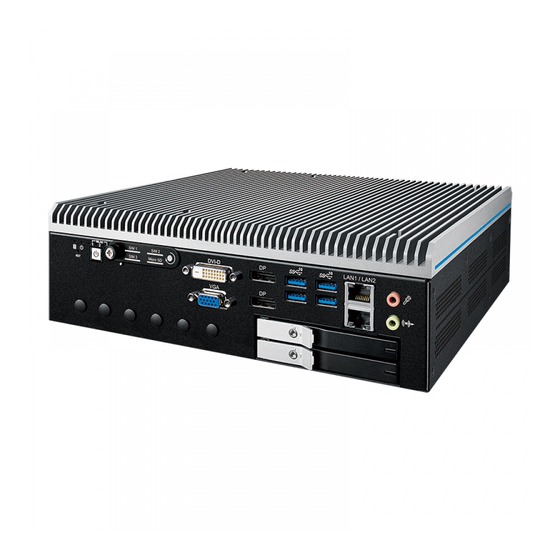
2.2 Front Panel I/O Functions In Vecow ECX-2200/2100 PEG series family, all I/O connectors are located on front panel and rear panel. Most of the general connections to computer device, such as USB, LAN Jack, Display, VGA, DVI-D, Display Port and any additional storage, are placed on the front panel. - Page 25 1920 x 1200 resolution. The DVI is automatically selected according to the display device connected. You will need a DVI-D cable when connecting to a display device. ©Vecow ECX-2200/2100 PEG User Manual GETTING TO KNOW YOUR ECX-2200/2100 PEG...
- Page 26 11 15 Ground Ground Ground Ground Ground DDC-DATA H-Sync. V-Sync. DDC-CLK 2.2.6 DisplayPort Onboard Display Port support auxiliary channel dual mode, connection supports up to 4096x2304 resolution at 60 Hz. ©Vecow ECX-2200/2100 PEG User Manual GETTING TO KNOW YOUR ECX-2200/2100 PEG...
- Page 27 2.2.8 WLAN LED, Mini PCIe, SIM Card, Micro SD Comparison Mini PCIe Slot/SIM Slot/Micro SD/WLAN LED Mapping Table : MPCIe/M.2 Nano SIM MPCIe 1 SIM 1 MPCIe 2 SIM 2 M.2 KEY B SIM 3 Micro SD ©Vecow ECX-2200/2100 PEG User Manual GETTING TO KNOW YOUR ECX-2200/2100 PEG...
- Page 28 Micro SD MPCIE SIM2 MPCIE SIM1 Note : The SIM card sockets do not support hot-plug. Please make sure to unplug the system power before inserting the SIM card(s). ©Vecow ECX-2200/2100 PEG User Manual GETTING TO KNOW YOUR ECX-2200/2100 PEG...
- Page 29 Ethernet data packets are being transmitted/received. LED Location LED Color 10Mbps 100Mbps 1000Mbps Green/ Solid Solid Right Orange Green Orange Twinkling Twinkling Twinkling Left Green Green Green Green ©Vecow ECX-2200/2100 PEG User Manual GETTING TO KNOW YOUR ECX-2200/2100 PEG...
- Page 30 2.2.11 SSD/HDD Tray There are 4 front-access 2.5" SSD/HDD trays in the front side of ECX-2200/2100 PEG series. Just trigger to open the SSD/HDD tray, up to 4TB is available. ©Vecow ECX-2200/2100 PEG User Manual GETTING TO KNOW YOUR ECX-2200/2100 PEG...
-
Page 31: Rear Panel I/O & Functions
You could turn on or off the system power by using this contact. This terminal block supports dual function of soft power-on/power-off (instant off or delay 4 second), and suspend mode. Pin No. Definition Pin No. Definition Ignition ©Vecow ECX-2200/2100 PEG User Manual GETTING TO KNOW YOUR ECX-2200/2100 PEG... - Page 32 2.3.3 Isolated DIO/GPIO 2.3.3.1 ECX-2200 PEG Series Isolated DIO2 Isolated DIO1 DC-IN On / Off PoE+ PoE+ PoE+ PoE+ PIN 1 ~ 8 PIN 11 ~ 18 PIN 1 ~ 8 PIN 11 ~ 18 LAN 3 LAN 4 LAN 5...
- Page 33 Sink Mode Power DIO Connector (NPN) Supply DI_COM (Pin 9) 6-48V DC DI (Pin 1-8) Source Mode Power DIO Connector (PNP) Supply DI_COM (Pin 9) 6-48V DC DI (Pin 1-8) ©Vecow ECX-2200/2100 PEG User Manual GETTING TO KNOW YOUR ECX-2200/2100 PEG...
- Page 34 Pin No. Mapping to SIO GPIO Function Pin No. Mapping to SIO GPIO Function SIO_GPI80 SIO_GPI81 SIO_GPI82 SIO_GPI83 SIO_GPI84 SIO_GPI85 SIO_GPI86 SIO_GPI87 SIO_GPO70 SIO_GPO71 SIO_GPO72 SIO_GPO73 SIO_GPO74 SIO_GPO75 SIO_GPO76 SIO_GPO77 ©Vecow ECX-2200/2100 PEG User Manual GETTING TO KNOW YOUR ECX-2200/2100 PEG...
- Page 35 (9-wire) (3-wire) TXD- TXD- DATA- TXD+ TXD+ DATA+ RXD+ RXD+ ----------- RXD- RXD- ----------- 1 to 4 ----------- RTS- ----------- ----------- RTS+ ----------- ----------- CTS+ ----------- ----------- CTS- ----------- ©Vecow ECX-2200/2100 PEG User Manual GETTING TO KNOW YOUR ECX-2200/2100 PEG...
- Page 36 MB Connector COM Port MB Connector COM 1 CN61 COM 2 CN62 COM 3 CN63 COM 4 CN64 Pin No. Signal Name CN61 to CN64 CN63 CN61 CN64 CN62 ©Vecow ECX-2200/2100 PEG User Manual GETTING TO KNOW YOUR ECX-2200/2100 PEG...
- Page 37 COM 3 COM 2 COM 4 There are 4 RJ45 connectors in the rear side of ECX-2200 PEG. It supports IEEE 802.3at (PoE ) Power over Ethernet (PoE) connection delivering up to 37W/54V per port and 1000BASE-T gigabit data signals over standard Ethernet Cat 5/Cat 6 cable.
-
Page 38: Main Board Expansion Connectors
With Connector Location SYS FAN 1 MPCIE 1 MPCIE 2 CN22 M2E CN1 M2E CN2 JBAT1 M2B CN1 CN63 CN61 SODIMM_1 SODIMM_2 CN64 CN62 SATA1 HDD_PWR_J1 CN59 SATA2 HDD_PWR_J2 CN31 CN17 ©Vecow ECX-2200/2100 PEG User Manual GETTING TO KNOW YOUR ECX-2200/2100 PEG... - Page 39 2.4.2 Bottom View (Solder Side) of ECX-2200/2100 PEG Main Board With Connector Location CPU_FAN2 CPU_FAN1 ©Vecow ECX-2200/2100 PEG User Manual GETTING TO KNOW YOUR ECX-2200/2100 PEG...
- Page 40 The pin-outs of Miscellaneous port are listed in following table : Group Pin No. Description HDD_LED_P HDD LED HDD_LED_N FP_RST_BTN_N RESET BUTTON Ground PWR_LED_P POWER LED PWR_LED_N FP_PWR_BTN_IN POWER BUTTON Ground ©Vecow ECX-2200/2100 PEG User Manual GETTING TO KNOW YOUR ECX-2200/2100 PEG...
- Page 41 5V (Up to 2A) and 12V (Up to 2A) current to the hard drive or SSD. The pin assignments of HDD_PWR_J1 to HDD_PWR_J2 are listed in the following table : HDD_PWR_J1 HDD_PWR_J2 Pin No. Definition Pin No. Definition +12V ©Vecow ECX-2200/2100 PEG User Manual GETTING TO KNOW YOUR ECX-2200/2100 PEG...
- Page 42 Description SODIMM_1 DDR4 Channel A SODIMM_2 DDR4 Channel B 2.4.7 CN22 : BIOS Socket If the BIOS needs to be changed, please contact the Vecow RMA service team. CN22 ©Vecow ECX-2200/2100 PEG User Manual GETTING TO KNOW YOUR ECX-2200/2100 PEG...
- Page 43 MPCIE 2 The pin assignments of MPCIe 1 ted in the following table : Pin No. Signal Name Pin No. Signal Name Reserved +3.3Vaux Reserved Reserved +1.5V Reserved Reserved ©Vecow ECX-2200/2100 PEG User Manual GETTING TO KNOW YOUR ECX-2200/2100 PEG...
- Page 44 The system's real-time clock is powered by a lithium battery. It is Equipped with MuRata CR2032 190mAh lithium battery. It is recommended that you not replace the lithium battery on your own. If the battery needs to be changed, please contact the Vecow RMA service team. JBAT1 Pin No.
- Page 45 Fan power connector supports for additional thermal requirements. The pin assignments of CPU_FAN1 and CPU_FAN2 are listed in the following table. CPU_FAN2 CPU_FAN1 Pin No. Function +12V (2A max) Fan speed sensor Fan PWM ©Vecow ECX-2200/2100 PEG User Manual GETTING TO KNOW YOUR ECX-2200/2100 PEG...
- Page 46 2.4.12 SYS_FAN1 : System Fan Header Fan power connector supports for additional PEG device. The pin assignments of SYS_FAN1 is listed in the following table. SYS FAN 1 Pin No. Function +12V (2A max) ©Vecow ECX-2200/2100 PEG User Manual GETTING TO KNOW YOUR ECX-2200/2100 PEG...
- Page 47 M2B_CN1 : M.2 KEY B (Dimension : 2280, 2242, 3042, 3050, 3052) Pin No. Signal Name Pin No. Signal Name Ground Ground 3.3V Ground 3.3V CONFIG_1 3.3V SIM DETECT Ground REFCLKp REFCLKn PEWAKE# Ground CLKREQ# PETp0/SATA-A+ PERST# ©Vecow ECX-2200/2100 PEG User Manual GETTING TO KNOW YOUR ECX-2200/2100 PEG...
- Page 48 Signal Name PETn0/SATA-A- Ground PERp0/SATA-B- PERn0/SATA-B+ Ground PETp1/USB3.1-Tx+ DEVSLP PETn1/USB3.1-Tx- UIM-PWR Ground UIM-DATA PERp1/USB3.1-Rx+ UIM-CLK PERn1/USB3.1-Rx- UIM-RESET Ground Mechanical Key Ground USB- LED_1# USB+ W_DISABLE1 FULL_CARD_PWR_OFF/ Ground Ground 3.3V 3.3V ©Vecow ECX-2200/2100 PEG User Manual GETTING TO KNOW YOUR ECX-2200/2100 PEG...
- Page 49 PERn0/SATA_B+ Ground PETp1 DEVSLP PETn1 Ground PERp1 PERn1 Ground PETp2 PETn2 Ground PERp2 PERn2 3.3V Ground 3.3V PETp3 3.3V PETn3 3.3V Ground LED1# PERp3 PERn3 Ground 3.3V Ground 3.3V ©Vecow ECX-2200/2100 PEG User Manual GETTING TO KNOW YOUR ECX-2200/2100 PEG...
- Page 50 I2C_CLK Ground I2C_DATA PEWAKE0# CLKREQ0# Ground PERST0# REFCLKn0 REFCLKp0 Ground PERn0 PERp0 Ground PETn0 DEVSLP PETp0 Ground Mechanical Key Ground Ground Ground Ground USB- LED1# USB+ 3.3V Ground 3.3V ©Vecow ECX-2200/2100 PEG User Manual GETTING TO KNOW YOUR ECX-2200/2100 PEG...
-
Page 51: Main Board Jumper Settings
To "open" a jumper, you remove the clip. Sometimes a jumper will have three pins, labeled 1, 2 and 3. In this case you would connect either pins 1 and 2, or 2 and 3. Open Closed Closed 2-3 ©Vecow ECX-2200/2100 PEG User Manual GETTING TO KNOW YOUR ECX-2200/2100 PEG... - Page 52 PIN 1 ~ 8 PIN 11 ~ 18 PIN 1 ~ 8 PIN 11 ~ 18 LAN 3 LAN 4 LAN 5 LAN 6 COM 1 COM 3 COM 2 COM 4 ©Vecow ECX-2200/2100 PEG User Manual GETTING TO KNOW YOUR ECX-2200/2100 PEG...
- Page 53 7 - 8 +5V (1A max.) 9 - 10 +12V (0.5A max.) COM2 9 - 10 +12V (0.5A max.) COM4 11 - 12 RI (Default) 11 - 12 RI (Default) ©Vecow ECX-2200/2100 PEG User Manual GETTING TO KNOW YOUR ECX-2200/2100 PEG...
- Page 54 PoE power on at standby power ready PoE power on after system power on (Default) No Jumper Disable PoE power 2.5.5 JCMOS1 : Clear CMOS JCMOS1 JCMOS1 : Setting Function *Normal (Default) Clear CMOS ©Vecow ECX-2200/2100 PEG User Manual GETTING TO KNOW YOUR ECX-2200/2100 PEG...
- Page 55 JP1, JP2 logic setting are listed in the following table. Logic Logic JP1, JP2 PCI Express configurations are listed in the following table. PCI Express* Bifurcation 1 x8 PCI Express* 2 x8 PCI Express* 1 x16 PCI Express* ©Vecow ECX-2200/2100 PEG User Manual GETTING TO KNOW YOUR ECX-2200/2100 PEG...
- Page 56 2.5.7 JIGNMODE1 : IGNITION Mode JIGNMODE1 JIGNMODE1 : Setting Function H/W mode S/W mode (default) ©Vecow ECX-2200/2100 PEG User Manual GETTING TO KNOW YOUR ECX-2200/2100 PEG...
-
Page 57: Ignition Control
ECX-2200/2100 PEG series provides 16 modes of different power on/off delay periods adjustable via SW2 switch. The default switch is set to 0 in ATX/AT power mode. SW2 : Ignition Control ©Vecow ECX-2200/2100 PEG User Manual GETTING TO KNOW YOUR ECX-2200/2100 PEG... - Page 58 60 seconds 5 seconds 90 seconds 5 seconds 120 seconds 10 seconds 10 seconds 10 seconds 30 seconds 10 seconds 60 seconds 10 seconds 90 seconds 10 seconds 120 seconds ©Vecow ECX-2200/2100 PEG User Manual GETTING TO KNOW YOUR ECX-2200/2100 PEG...
- Page 59 3. For proper ignition control, the power button setting should be "Power Down" mode. In Windows for example, you need to set "When I press the power button" to Shut down. ©Vecow ECX-2200/2100 PEG User Manual GETTING TO KNOW YOUR ECX-2200/2100 PEG...
-
Page 60: Chapter 3 System Setup
SYSTEM SETUP 3.1 How to Open Your ECX-2200/2100 PEG 3.1.1 ECX-2200F & ECX-2100F Series Step 1 Remove the screws indicated and separate Cover Fan Cpu from the enclosure. ©Vecow ECX-2200/2100 PEG User Manual SYSTEM SETUP... - Page 61 Step 2 Remove the plugs indicated. Step 3 Remove the screws indicated and separate the cooler from the enclosure. ©Vecow ECX-2200/2100 PEG User Manual SYSTEM SETUP...
- Page 62 3.1.2 ECX-2200 & ECX-2100 Series Step 1 Remove the screws indicated and separate the heat sink from the enclosure. ©Vecow ECX-2200/2100 PEG User Manual SYSTEM SETUP...
-
Page 63: Installing Cpu
3.2 Installing CPU Step 1 Open CPU Independent Step 2 Install CPU (Be careful CPU Loading Mechanism (ILM). pin). Step 3 Remove the mylar. Step 4 Close CPU Independent Loading Mechanism (ILM) and finish. ©Vecow ECX-2200/2100 PEG User Manual SYSTEM SETUP... -
Page 64: Installing Ddr4 So-Dimm Modules
3.3 Installing DDR4 SO-DIMM Modules Step 1 Turn the system upside-down on a steady surface. Remove the screws indicated. Step 2 Open Cover Bottom HDD Tray and separate Cover Bottom Riser Card from the enclosure. ©Vecow ECX-2200/2100 PEG User Manual SYSTEM SETUP... - Page 65 Step 3 Separate Assembly_Riser Card from the enclosure with the puller. Step 4 Install DDR4 RAM module into SO-DIMM socket. ©Vecow ECX-2200/2100 PEG User Manual SYSTEM SETUP...
-
Page 66: Installing Mini Pcie Card
3.4 Installing Mini PCIe Card Step 1 Turn the system upside-down on a steady surface. Remove the screws indicated. Step 2 Open Cover Bottom HDD Tray and separate Cover Bottom Riser Card from the enclosure. ©Vecow ECX-2200/2100 PEG User Manual SYSTEM SETUP... - Page 67 Step 3 Separate Assembly_Riser Card from the enclosure with the puller. Step 4 Install mini PCIe card into slot. ©Vecow ECX-2200/2100 PEG User Manual SYSTEM SETUP...
- Page 68 Step 5 Fasten one PHILLPIS M2.5 screw. ©Vecow ECX-2200/2100 PEG User Manual SYSTEM SETUP...
-
Page 69: Installing Nano Sim Card
3.5 Installing Nano SIM Card Step 1 Loosen captive panel screw and open Cover Card. Step 2 Open Cover Card. Step 3 Insert Nano SIM card and push to lock. ©Vecow ECX-2200/2100 PEG User Manual SYSTEM SETUP... -
Page 70: Installing Micro Sd Cards
3.6 Installing Micro SD Cards Step 1 Loosen captive panel screw and open Cover Card. Step 2 Open Cover Card. Step 3 Insert Micro SD card and push to lock. ©Vecow ECX-2200/2100 PEG User Manual SYSTEM SETUP... -
Page 71: Installing Pci/Pcie Card
I/O bracket & auxiliary power cable) PCI/PCI Express add-in cards. Step 1 Turn the system upside-down on a steady surface. Remove the screws indicated. Step 2 Open Cover Bottom HDD Tray and separate Cover Bottom Riser Card from the enclosure. ©Vecow ECX-2200/2100 PEG User Manual SYSTEM SETUP... - Page 72 Step 3 Separate Assembly_Riser Card from the enclosure with the puller. Step 4 Turn Assembly_Riser Card upside-down on a steady surface. ©Vecow ECX-2200/2100 PEG User Manual SYSTEM SETUP...
- Page 73 Step 5 Remove the screw indicated and separate I/O bracket from Assembly Riser Card. Step 6 Instal PCI/PCIe card and fasten the screw indicated. ©Vecow ECX-2200/2100 PEG User Manual SYSTEM SETUP...
-
Page 74: Installing Ssd/Hdd
Step 1 Use the trigger and open Step 2 Open front door of SSD/HDD SSD/HDD tray. tray. Step 3 Install 2.5" SSD/HDD into the Step 4 Lock the SSD/HDD tray with tray and close. key. ©Vecow ECX-2200/2100 PEG User Manual SYSTEM SETUP... -
Page 75: Installing
3.9.1 Key E 2230, Key M 2280 Step 1 Turn the system upside-down on a steady surface. Remove the screws indicated. Step 2 Open Cover Bottom HDD Tray and separate Cover Bottom Riser Card from the enclosure. ©Vecow ECX-2200/2100 PEG User Manual SYSTEM SETUP... - Page 76 Step 3 Separate Assembly_Riser Card from the enclosure with the puller. Step 4 Install M.2 module into the slot. ©Vecow ECX-2200/2100 PEG User Manual SYSTEM SETUP...
- Page 77 Step 5 Fasten the module with the screw indicated. ©Vecow ECX-2200/2100 PEG User Manual SYSTEM SETUP...
- Page 78 3.9.2 Key B 2242, 3050, 3052, 2280 Step 1 Turn the system upside-down on a steady surface. Remove the screws indicated. ©Vecow ECX-2200/2100 PEG User Manual SYSTEM SETUP...
- Page 79 Step 2 Open Cover Bottom HDD Tray and separate Cover Bottom Riser Card from the enclosure. Step 3 Separate Assembly_Riser Card from the enclosure with the puller. ©Vecow ECX-2200/2100 PEG User Manual SYSTEM SETUP...
- Page 80 Step 4 Change the position of the standoff indicated, When using Key B 3050, 3052, 2280. Step 5 Install M.2 module into the slot. ©Vecow ECX-2200/2100 PEG User Manual SYSTEM SETUP...
- Page 81 Step 6 Fasten the module with the screw indicated. ©Vecow ECX-2200/2100 PEG User Manual SYSTEM SETUP...
-
Page 82: Installing Antenna Cable
3.10 Installing Antenna Cable Step 1 Check antenna cable and washer. Step 2 Turn the system upside-down on a steady surface. Remove the screws indicated. ©Vecow ECX-2200/2100 PEG User Manual SYSTEM SETUP... - Page 83 Step 3 Open Cover Bottom HDD Tray and separate Cover Bottom Riser Card from the enclosure. Step 4 Separate Assembly Riser Card from the enclosure with the puller. ©Vecow ECX-2200/2100 PEG User Manual SYSTEM SETUP...
- Page 84 Step 5 Install the cable with nut and washer indicated. ©Vecow ECX-2200/2100 PEG User Manual SYSTEM SETUP...
-
Page 85: Mounting Your Ecx-2200/2100 Peg
3.11 Mounting Your ECX-2200/2100 PEG 3.11.1 Wall Mount Step 1 Loosen the screws (4 pcs) indicated. Step 2 Install the brackets with the screws (6 pcs) indicated. ©Vecow ECX-2200/2100 PEG User Manual SYSTEM SETUP... - Page 86 3.11.2 VESA Mount Install the brackets with the screws (6 pcs) indicated. 3.11.3 DIN Rail Mount ©Vecow ECX-2200/2100 PEG User Manual SYSTEM SETUP...
- Page 87 3.11.4 2U Rack Mount Step 1 Loosen captive panel screw and open Cover Top. Step 2 Open Cover Top. ©Vecow ECX-2200/2100 PEG User Manual SYSTEM SETUP...
- Page 88 Step 3 Remove the screws and the nuts indicated. Step 4 Open Cover Rear. ©Vecow ECX-2200/2100 PEG User Manual SYSTEM SETUP...
- Page 89 Step 5 Fasten the nuts indicated. ©Vecow ECX-2200/2100 PEG User Manual SYSTEM SETUP...
-
Page 90: Chapter 4 Bios Setup
Figure 4-1 : Entering Setup Screen BIOS provides an interface for users to check and change system configuration. The BIOS setup program is accessed by pressing the <Del> key when POST display output is shown. ©Vecow ECX-2200/2100 PEG User Manual BIOS SETUP... -
Page 91: Main
Set the time. Use <Tab> to switch between time elements. 4.3 Advanced Figure 4-3 : BIOS Advanced Menu Select advanced tab to enter advanced BIOS setup options, such as CPU configuration, SATA configuration, and USB configuration. ©Vecow ECX-2200/2100 PEG User Manual BIOS SETUP... - Page 92 Technology). When disabled only one thread per core is enabled. Enable/disable CPU Advanced Encryption Standard instructions. Intel Trusted Execution Technology ® Enables utilization of additional hardware capabilities provided by Intel Trusted Execution Technology. Changes require a full power cycle to take effect. ©Vecow ECX-2200/2100 PEG User Manual BIOS SETUP...
- Page 93 Enable/disable C1E. When enabled, CPU will switch to minimum speed when all cores enter C-State. Dual Tau Boost Enable Dual Tau Boost feature. This is only applicable for CML-S 35W/ 65W/125W sku. When DPTF is enabled, this feature is ignored. ©Vecow ECX-2200/2100 PEG User Manual BIOS SETUP...
- Page 94 MEBx Setup. AMT Configuration ® Configure Intel Active Management Technology Parameters. ME Unconfig on RTC Clear State Disabling this option will cause ME not to unconfigure on RTC clear. ©Vecow ECX-2200/2100 PEG User Manual BIOS SETUP...
- Page 95 Enables or disables S3 video repost. 4.3.6 SMART Settings Figure 4-3-6 : SMART Settings SMART Self Test Run SMART self test on all HDDs during POST. 4.3.7 IT8786 Super IO Configuration Figure 4-3-7 : IT8786 Super IO Settings ©Vecow ECX-2200/2100 PEG User Manual BIOS SETUP...
- Page 96 Temperature Limit value of Fan Start (Degree C). (Range : 10~80) PWM Start Value (%) Default PWM Value of Fan. (Range : 15%~100%) Full Speed Temperature Temperature Limit value of Fan Full Speed (Degree C). (Range : 50~90) ©Vecow ECX-2200/2100 PEG User Manual BIOS SETUP...
- Page 97 Legacy Console Redirection Legacy Console Redirection Settings. Serial Port for Out-of-Band Management/Windows Emergency Management Services (EMS) Console redirection enable or disable. 4.3.10 Intel TXT Information Figure 4-3-10 : Intel TXT Information Display Intel TXT information. ©Vecow ECX-2200/2100 PEG User Manual BIOS SETUP...
- Page 98 Globally Enables or Disables Hot-Plug support for the entire System. If system has Hot-Plug Capable Slots and this option set to Enabled, it provides a Setup screen for selecting PCI resource padding for Hot-Plug. ©Vecow ECX-2200/2100 PEG User Manual BIOS SETUP...
- Page 99 IP6 Configuration Policy Set IP6 Configuration Policy. PXE boot wait time Wait time to press ESC key to abort the PXE boot. Media detect count Number of times presence of media will be checked. ©Vecow ECX-2200/2100 PEG User Manual BIOS SETUP...
- Page 100 Maximum time the device will take before it properly reports itself to the Host Controller. 'Auto' uses default value, for a root port it is 100 ms, for a hub port the delay is taken from the hub descriptor. ©Vecow ECX-2200/2100 PEG User Manual BIOS SETUP...
- Page 101 This should be enabled only if both WWAN and WLAN solutions are based on Intel components Discrete Bluetooth Module SerialIo UART0 needs to be enabled to select BT Module Advanced settings Configure ACPI objects for wireless devices WWAN Configuration Configure WWAN related options ©Vecow ECX-2200/2100 PEG User Manual BIOS SETUP...
-
Page 102: Chipset
4.4.1 System Agent (SA) Configuration Figure 4-4-1 : System Agent Settings VT-d VT-d capability. Above 4GB MMIO BIOS assignment Enable/disable above 4GB MemoryMappedIO BIOS assignment. This is disabled automatically when aperture size is set to 2048MB. ©Vecow ECX-2200/2100 PEG User Manual BIOS SETUP... - Page 103 2048MB aperture. To use this feature, please disable CSM Support. DVMT Pre-Allocated Select DVMT 5.0 Pre-Allocated (Fixed) Graphics Memory size used by the Internal Graphics Device. DVMT Total Gfx Mem Select DVMT5.0 Total Graphic Memory size used by the Internal Graphics Device. ©Vecow ECX-2200/2100 PEG User Manual BIOS SETUP...
- Page 104 Specify what state to go to when power is re-applied after a power failure (G3 state). S0 State : Always turn-on the system when power source plugged-in. S5 State : Always turn-off the system when power source plugged-in. ©Vecow ECX-2200/2100 PEG User Manual BIOS SETUP...
- Page 105 Enable/Disable the control of Active State Power Management on SA side of the DMI Link. Native PCIE Enable PCIE Express Native Support Enable/Disable. PCI Express device settings Bios options for PCI Express device setting. ©Vecow ECX-2200/2100 PEG User Manual BIOS SETUP...
- Page 106 On an edge detect from 0 to 1, the PCH starts a COMRESET initialization sequence to the device. SATA Device Type Identifies that the SATA port is connected to solid state drive or hard disk drive. ©Vecow ECX-2200/2100 PEG User Manual BIOS SETUP...
- Page 107 [Ignition] System power on by ignition pin Delay On Timer (Second) The delay times after user trigger ignition on signal Delay Off Timer (Second) The delay times after user trigger ignition off signal ©Vecow ECX-2200/2100 PEG User Manual BIOS SETUP...
-
Page 108: Security
Voltage Guard Higher limit value setting range : 15V~55V 4.5 Security Figure 4-5 : BIOS Security Menu Administrator Password Set administrator password. User Password Set user password. Secure Boot Customizable Secure Boot Settings. ©Vecow ECX-2200/2100 PEG User Manual BIOS SETUP... - Page 109 Secure Boot Mode Secure Boot mode selector Standard/Custom. In custom mode Secure Boot Variables can be configured without authentication Key Management Enables expert users to modify Secure boot policy variables without full authentication ©Vecow ECX-2200/2100 PEG User Manual BIOS SETUP...
-
Page 110: Boot
Boot Option Sets the system boot order. New Boot Option Policy Controls the placement of newly detected UEFI boot options. Hard Drive BBS Priorities Set the order of the Legacy devices in this group. ©Vecow ECX-2200/2100 PEG User Manual BIOS SETUP... -
Page 111: Save & Exit
Restore/Load Default values for all the setup options. Save as User Defaults Save the changes done so far as User Defaults. Restore User Defaults Restore the User Defaults to all the setup options ©Vecow ECX-2200/2100 PEG User Manual BIOS SETUP... -
Page 112: Appendix A : Isolated Dio/Gpio Guide
Do NOT use these functions in below : 1. PE-2000 : DIO1 (ID = 0), POE 2. PE-3000 : POE 3. UE-1000 : USB (ID = 0) LAN 3 LAN 4 LAN 5 LAN 6 ©Vecow ECX-2200/2100 PEG User Manual Appendix A... - Page 113 DIO Connector (NPN, Default) 6-48V DC DIO_VDC (Pin 20) DO (Pin 11-18) DIO_GND (Pin 10, 19) Source Mode Device DIO Connector (PNP) 6-48V DC DIO_VDC (Pin 20) DO (Pin 11-18) DIO_GND (Pin 10, 19) ©Vecow ECX-2200/2100 PEG User Manual Appendix A...
- Page 114 Header folder include head file for software developer or System Integration. Manual folder include API description. Sample folder include sample program, driver library, and API library for Windows/Linux Source folder include sample program source code that compile on Visual Studio 2008/ubuntu16.04. ©Vecow ECX-2200/2100 PEG User Manual Appendix A...
- Page 115 A.4 Sample Execute demo tool. Windows Linux Sample, as shown below : Vecow_DIO Vecow_DIO_loopback Vecow_POE Vecow_WDT ©Vecow ECX-2200/2100 PEG User Manual Appendix A...
-
Page 116: Appendix B : Software Functions
APPENDIX B : Software Functions B.1 Driver API Guide In Header folder, Vecow.h and VecowLinux.h contain usabled API for Windows/Linux. BOOL initial_SIO(BYTE Isolate_Type, BYTE DIO_NPN) Initial machine for IO and watch dogtimer. Isolate_Type : DIO type. 1 : Isolated DIO;... - Page 117 DO ([7:0]) : Output state, pin setting by hexadecimal bitmask. 1 : High; 0 : Low. Return : TRUE (1) : Success. FALSE (0) : Fail (Initial error or hardware problem). FALSE (0) : Fail (Initial error or hardware problem). ©Vecow ECX-2200/2100 PEG User Manual Appendix B...
- Page 118 FALSE (0) : Fail (Driver not exists, or version is too old, or out of range error). BOOL get_POE_configuration(BYTE ID, BYTE *Auto, BYTE *Mask) Get POE configuration (by variable). ID : POE ID. Range : 0~15. Auto ([3:0]) : Auto mode, pin setting by hexadecimal bitmask. ©Vecow ECX-2200/2100 PEG User Manual Appendix B...
- Page 119 B. POE ([3:0]) : POE state, pin setting by hexadecimal bitmask. 1 : On; 0 : Off. Return : TRUE (1) : Success. FALSE (0) : Fail (Initial error, or out of range error, or hardware problem). ©Vecow ECX-2200/2100 PEG User Manual Appendix B...
-
Page 120: Appendix C : Raid Functions
Selection → Intel RST Premium → Save Changes and Reset. C.1.2 UEFI Mode for RAID 1. Into BIOS menu again, select Intel(R) Rapid Storage Technology on BIOS menu. Advanced → Intel(R) Rapid Storage Technology ©Vecow ECX-2200/2100 PEG User Manual Appendix C... - Page 121 3. Select Create RAID Volume on BIOS menu. 4. Select disks to create RAID Volume then Save Changes and Reset to install OS with EFI mode. ©Vecow ECX-2200/2100 PEG User Manual Appendix C...
- Page 122 The RAID environment has been done if you completed the steps above. C.5 To Insert SATA HDD for RAID 1 Please note, you can use two SATA ports for SATA HDD, except for mSATA slot. ©Vecow ECX-2200/2100 PEG User Manual Appendix C...
- Page 123 Let's take RAID 1 as an example, select"RAID 1". C.7 Disk Management : Partition the Disk After RAID 1 volume is created, you can see the figure of SATA device allocation. You will find"Volume_0000" in SATA device at BIOS menu. ©Vecow ECX-2200/2100 PEG User Manual Appendix C...
- Page 124 Then add"Logical Device" for Windows access. C.8 If One SATA HDD on RAID Volume is Out-of-use After RAID 1 volume is created, you can see the figure of SATA device allocation. HDD CAUTION Sign ©Vecow ECX-2200/2100 PEG User Manual Appendix C...
- Page 125 A warning will pop-up to ask you if the disk is not a member of the original RAID volume. If you press"Rebuild", it will replace the broken SATA HDD to the last SATA HDD of RAID volume. ©Vecow ECX-2200/2100 PEG User Manual Appendix C...
-
Page 126: Appendix D : Power Consumption
SATA 1 Seagate HDD 500GB LAN 1 (i219) 1.0 Gbps LAN 2 (i210) 1.0 Gbps Graphics Output Power Plan Balance (Windows10 Power plan) Power Source Chroma 62006P-100-25 Test Program-1 BurnInTest Test Program-2 FurMark ©Vecow ECX-2200/2100 PEG User Manual Appendix D... - Page 127 Input Current Consumption Current Consumption Core™ i7- 4.038A 36.34W 4.619A 41.57W 10700TE Core™ i7- 3.510A 42.12W 3.601A 43.21W 10700TE Core™ i7- 1.780A 42.72W 1.817A 43.60W 10700TE Core™ i7- 0.968A 48.40W 0.997A 49.85W 10700TE ©Vecow ECX-2200/2100 PEG User Manual Appendix D...
- Page 128 Input Current Consumption Current Consumption Core™ i5- 5.992A 53.93W 7.059A 63.53W 10500E Core™ i5- 4.415A 52.98W 6.151A 73.82W 10500E Core™ i5- 2.414A 57.94W 2.506A 60.15W 10500E Core™ i5- 1.264A 63.19W 1.495A 74.76W 10500E ©Vecow ECX-2200/2100 PEG User Manual Appendix D...
- Page 129 Input Current Consumption Current Consumption ® Xeon 9.308A 83.77W 9.459A 85.13W W-1270E Xeon ® 6.660A 79.92W 6.775A 81.29W W-1270E ® Xeon 3.412A 81.89W 3.478A 83.46W W-1270E ® Xeon 1.779A 88.95W 1.886A 94.30W W-1270E ©Vecow ECX-2200/2100 PEG User Manual Appendix D...
- Page 130 Input Current Consumption Current Consumption ® Xeon 11.804A 106.23W 13.300A 119.70W W-1290E Xeon ® 8.319A 99.83W 8.462A 101.55W W-1290E ® Xeon 4.195A 100.67W 4.241A 101.79W W-1290E ® Xeon 2.123A 106.15W 2.164A 108.22W W-1290E ©Vecow ECX-2200/2100 PEG User Manual Appendix D...
- Page 131 Input Current Consumption Current Consumption Core™ i5- 6.626A 59.63W 12.920A 116.28W 10500E Core™ i5- 4.876A 58.51W 9.752A 117.03W 10500E Core™ i5- 2.576A 61.82W 5.011A 120.26W 10500E Core™ i5- 1.370A 68.50W 2.518A 125.90W 10500E ©Vecow ECX-2200/2100 PEG User Manual Appendix D...
-
Page 132: Appendix E : Supported Memory & Storage List
Memory Test MemTest86 V8.4 BurnInTest BurnInTest Pro V8.1 (build 1025) Channel Memtest Bunin Flash BIOS Remove Battery PASS PASS PASS PASS *1 (Socket 1) PASS PASS PASS *1 (Socket 2) PASS PASS PASS ©Vecow ECX-2200/2100 PEG User Manual Appendix E... - Page 133 Innodisk 16GB DDR4-3200 SODIMM M4S0-AGS1O5EM-H03 25ºC Innodisk 32GB DDR4-3200 SODIMM M4S0-BGS2OCEM-H03 25ºC Innodisk 32GB DDR4-3200 SODIMM M4S0-BGS2O5EM-H03 25ºC AFASTOR 16G DDR4-3200 SODIMM STI2046SO410825-SD 25ºC AFASTOR 32G DDR4-3200 SODIMM ST4096SO420825SA 25ºC MEMXPRO 32GB DDR4-3200 SODIMM D4S-BG32M2G8W1 25ºC ©Vecow ECX-2200/2100 PEG User Manual Appendix E...
- Page 134 25ºC SL LINK 8GB DDR4-3200 SODIMM J48GDH1G8TMJC 25ºC SL LINK 16GB DDR4-3200 SODIMM J4AGDH1G8TMKC 25ºC AFASTOR 32GB DDR4-3200 SODIMM ST4097SO420825SA 25ºC Innodisk 32GB DDR4-3200 SODIMM M4D0-BGS2QCEM-H03 25ºC Innodisk 32GB DDR4-3200 SODIMM M4D0-BGS2Q5EM-H03 25ºC ©Vecow ECX-2200/2100 PEG User Manual Appendix E...
- Page 135 M.2 2280 SATA PM31 256GB 256GB ST FP28S-B5GTMS464C1 M.2 SSD M.2 2280 SATA PM31 512GB MEMXPRO 512GB SATA WT FP28S-E1GTMS464W1 M.2 2280 SATA PT31 512GB 512GB WT FP28S-E1GMTS594W1 M.2 (S80) 3TE7 Innodisk DEM28-01TDK1ECAQF-H03 ©Vecow ECX-2200/2100 PEG User Manual Appendix E...
- Page 136 DGM28-02TDA1ECBEH-H03 760P INTEL 128GB SSDPEKKW128G8 970 EVO PLUS SAMSUNG 250GB MZ-V7S250 FORESEE FSGPMMC-256G 256GB TOSHIBA KXG50ZNV512G 512GB SA1000M8 240GB Kingston SA2000MB 500GB ** If more help is needed, please contact Vecow Technical Support.** ©Vecow ECX-2200/2100 PEG User Manual Appendix E...
- Page 137 No part of this publication may be reproduced in any form or by any means, electric, photocopying, or recording, without prior authorization from the publisher. The rights of all the brand names, product names, and trademarks belong to their respective owners. © Vecow Co., Ltd. 2022. All rights reserved.
Need help?
Do you have a question about the ECX-2200 PEG and is the answer not in the manual?
Questions and answers