
Related Manuals for Vecow GPC-1000MX


Summary of Contents for Vecow GPC-1000MX
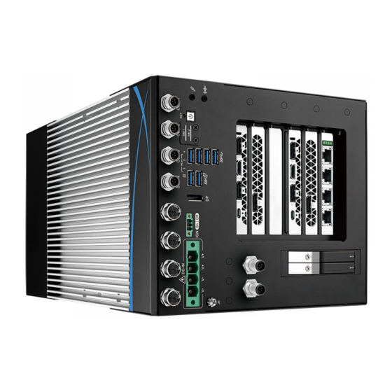
- Page 1 USER USER GPC-1000MX Manual Manual Intel ® Xeon ® /Core™ i7/i5/i3 Dual GPU AI Computing System Workstion- grade, NVIDIA ® Tesla ® /Quadro ® /GeForce ® /AMD Radeon™ Grraphics 1.0.0 Edition 20220701...
- Page 2 Record of Revision Version Date Page Description Remark 1.00 2022/7/1 Official Release ©Vecow GPC-1000MX User Manual...
- Page 3 This manual is released by Vecow Co., Ltd. for reference purpose only. All product offerings and specifications are subject to change without prior notice. Vecow Co., Ltd. is under no legal commitment to the details of this document. Vecow shall not be liable for direct, indirect, special, incidental, or consequential damages arising out of the use of this document, the products, or any third party infringements, which may result from such use.
- Page 4 Order Information Part Number Description GPC-1000MX, 4 M12 X-coded GigE LAN, 4 M12 A-coded COM, 2 GPC-1000MX M12 A-coded CAN Bus, 2 PCIe x8, 2 PCIe x4, 12-55V DC-in Optional Accessories Part Number Description DDR4 32G Certified DDR4 32GB 2666MHz RAM...
-
Page 5: Table Of Contents
1.3.1 Specifications of GPC-1000MX 1.4 Supported CPU List 1.5 Mechanical Dimension 1.5.1 Dimensions of GPC-1000MX CHAPTER 2 GETTING TO KNOW YOUR GPC-1000MX 2.1 Packing List 2.2 Front Panel I/O Functions 2.3 Main Board Expansion Connectors 2.4 Main Board DIP Switch Settings 2.5 Riser Board Connectors... - Page 6 4.5 Security Function 4.6 Boot 4.7 Save & Exit APPENDIX A : Driver/Sample Guide APPENDIX B : Software Functions APPENDIX C : RAID Functions APPENDIX D : Power Consumption APPENDIX E : Supported Memory & Storage List ©Vecow GPC-1000MX User Manual...
-
Page 7: Chapter 1 General Introduction
-25°C to 45°C, anti-shock, anti-vibration tested EN50155, EN50121-3-2. Support for 12V to 55V DC-in, ignition power control, CAN Bus, and TPM 2.0 makes GPC-1000MX a trusted solution for Rolling Stock, Railway Security and Industrial EV. -
Page 8: Features
• Expansion : 2 PCIe x8, 2 PCIe x4, 1 Mini PCIe, 1 M.2 Key E, 1 M.2 Key B • DC 12V to 55V Power Input, Ignition Power Control, TPM 2.0 Optional VHub AIoT Solution Service supports OpenVINO based AI accelerator and advanced Edge AI applications ©Vecow GPC-1000MX User Manual GENERAL INTRODUCTION... -
Page 9: Product Specification
1.3 Product Specification 1.3.1 Specifications of GPC-1000MX System ® ® 8-core 9th/8th Gen Intel Xeon /Core™ i7/i5/i3 Processor Processor (Coffee Lake Refresh) ® Chipset Intel C246 BIOS IT8786E Memory 4 DDR4 2133MHz SO-DIMM, up to 128GB (ECC/Non-ECC) I/O Interface Serial... - Page 10 -40°C to 85°C (-40°F to 185°F) Humidity 5% to 95% humidity, non-condensing Relative Humidity 95% at 45°C • IEC 61373 : 2010 Shock/ Vibration • Railway Applications : Rolling Stock Equipment, Shock and Vibration Tests CE, FCC, EN50155, EN50121-3-2 ©Vecow GPC-1000MX User Manual GENERAL INTRODUCTION...
-
Page 11: Supported Cpu List
® Intel ™ Core i5-8500T i5-9500TE i3-8100 i3-9100E i3-8100T i3-9100TE 1.5 Mechanical Dimension 1.5.1 Dimensions of GPC-1000MX Unit : mm (inch) 242.2 (9.54) 160.0 (6.30) R2.5 (0.10”) 243.0 (9.57”) ©Vecow GPC-1000MX User Manual GENERAL INTRODUCTION... -
Page 12: Chapter 2 Getting To Know Your Gpc-1000Mx
GETTING TO KNOW YOUR GPC-1000MX 2.1 Packing List Item Description GPC-1000MX AI Computing System (According to the configuration you order, the GPC-1000MX series may contain SSD/HDD and DDR4 SO-DIMM. Please verify these items if necessary.) Vecow Drivers & Utilities DVD Item... -
Page 13: Front Panel I/O Functions
2.2 Front Panel I/O Functions In Vecow’s GPC-1000MX , all I/O connectors are located on the front panel. Most of the general connections to the computer device, such as audio, USB, LAN, COM Port, Display Port, and any additional storage, are placed on the front panel. - Page 14 S3, S5 power To power on GPC-1000MX, press the power button which will light the blue LED.To power off GPC-1000MX, you can either command shutdown by OS operation or simply press the power button. If system error appears, press and hold the power button for four seconds to shut down the machine directly.
- Page 15 • On/Off : Device status, function or not. WLAN2 Green (MPCIE1) • Twinkling : Data transferring. WLAN3 • On/Off : Device status, function or not. Green (M2E_CN1) • Twinkling : Data transferring. 2.2.4 Display Port ©Vecow GPC-1000MX User Manual GETTING TO KNOW YOUR GPC-1000MX...
- Page 16 There are 2 USB 3.2 Gen2 Type A connections available supporting up to 10GB and 4 USB 3.2 Gen1 supporting up to 5GB per second data rate in the front side of GPC-1000MX. It also compliant with the requirements of Super Speed (SS), high speed (HS), full speed F(S) and low speed (LS).
- Page 17 LAN2_MDI_0P LAN3_MDI_0P LAN4_MDI_0P LAN1_MDI_0N LAN2_MDI_0N LAN3_MDI_0N LAN4_MDI_0N LAN1_MDI_1P LAN2_MDI_1P LAN3_MDI_1P LAN4_MDI_1P LAN1_MDI_1N LAN2_MDI_1N LAN3_MDI_1N LAN4_MDI_1N LAN1_MDI_3P LAN2_MDI_3P LAN3_MDI_3P LAN4_MDI_3P LAN1_MDI_3N LAN2_MDI_3N LAN3_MDI_3N LAN4_MDI_3N LAN1_MDI_2N LAN2_MDI_2N LAN3_MDI_2N LAN4_MDI_2N LAN1_MDI_2P LAN2_MDI_2P LAN3_MDI_2P LAN4_MDI_2P ©Vecow GPC-1000MX User Manual GETTING TO KNOW YOUR GPC-1000MX...
- Page 18 2.2.9 Front-access SSD/ HDD Tray There are four front-access 2.5” SSD/HDD trays on the front side of GPC- 1000MX. Press the trigger to open the SSD/HDD tray which has up to 8TB available. ©Vecow GPC-1000MX User Manual GETTING TO KNOW YOUR GPC-1000MX...
- Page 19 2.2.10 Power Terminal Block GPC-1000MX supports 12V to 55V DC power input. 2.2.11 Remote Power On/Off Switch It is a 2-pin power-on/power-off switch through Pin Number Definition Phoenix Contact terminal block. You could turn IGNITION on or off the system power by using this contact.
- Page 20 The pin assignments are listed in the table as follows: RS-422 RS-485 Serial Port Pin Number RS-232 (5-wire) (3-wire) TXD- DATA- TXD+ DATA+ RXD+ ----------- RXD- ----------- ----------- ----------- ----------- ----------- ----------- ----------- ----------- ----------- ©Vecow GPC-1000MX User Manual GETTING TO KNOW YOUR GPC-1000MX...
-
Page 21: Main Board Expansion Connectors
2.3 Main Board Expansion Connectors 2.3.1 TOP View of GPC-1000MX Main Board with Connector Location SATA1 SATA2 DCIN_CN1 HDD_PWR_J1 HDD_PWR_J2 JCFG1 M2M_CN1 M2B_CN1 MPCIE2 JIGNMODE1 IGN_SW1 DP_CN1 USB31_CN1 USB30_CN1 JCMOS1 MPCIE1_SIMI PWRBTIN M2E_CN1 SODIMM1 SODIMM3 MPCIE1 SODIMM2 SODIMM4 AUDIO_CN1 2.3.2 BOTTOM View of GPC-1000MX Main Board with Connector Location... - Page 22 2.3.4 BAT_CN1 : Battery BAT_CN1 GPC-1000MX’s real-time clock is powered by a lithium battery. It is equipped with Panasonic CR2032 220mAh lithium battery. It is recommended that you do not replace the lithium battery on your own. If the battery needs to be changed, please contact the Vecow RMA service team.
- Page 23 Function CLKOUT_100M_X8_P2 CLKOUT_100M_X8_N2 CLKOUT_100M_X8_N1 PCIE24_RX_N CLKOUT_100M_X8_P1 PCIE24_RX_P PCIE24_TX_N PCIE23_RX_N PCIE24_TX_P PCIE23_RX_P PCIE23_TX_N PCIE22_RX_N PCIE23_TX_P PCIE22_RX_P PCIE22_TX_N PCIE21_RX_N PCIE22_TX_P PCIE21_RX_P PCIE21_TX_N PCIE16_RX_N PCIE21_TX_P PCIE16_RX_P CLKOUT_100M_X4_N1 PCIE15_RX_N CLKOUT_100M_X4_P1 PCIE15_RX_P PCIE16_TX_N PCIE14_RX_N PCIE16_TX_P PCIE14_RX_P ©Vecow GPC-1000MX User Manual GETTING TO KNOW YOUR GPC-1000MX...
- Page 24 Function Pin No. Function PCIE15_TX_N PCIE13_RX_N PCIE15_TX_P PCIE13_RX_P PCIE14_TX_N PCIE14_TX_P PCIE13_TX_N PCIE13_TX_P CLKOUT_100M_X4_N2 CLKOUT_100M_X4_P2 +V3.3A +V3.3A +V3.3A +V3.3S +V3.3S +V3.3S +V3.3S +V3.3S +V3.3S +V3.3S +V3.3S +V3.3S +V3.3S +V3.3S +V3.3S +V3.3S +V3.3S ©Vecow GPC-1000MX User Manual GETTING TO KNOW YOUR GPC-1000MX...
- Page 25 Function +V12S +V12S +V12S +V12S +V12S +V12S +V12S +V12S +V12S +V12S PEG_RX_DN_15 PEG_TX_DN_15 PEG_RX_DP_15 PEG_TX_DP_15 PEG_RX_DN_14 PEG_TX_DN_14 PEG_RX_DP_14 PEG_TX_DP_14 PEG_RX_DN_13 PEG_TX_DN_13 PEG_RX_DP_13 PEG_TX_DP_13 PEG_RX_DN_12 PEG_TX_DN_12 PEG_RX_DP_12 PEG_TX_DP_12 PEG_RX_DN_11 PEG_TX_DN_11 PEG_RX_DP_11 PEG_TX_DP_11 ©Vecow GPC-1000MX User Manual GETTING TO KNOW YOUR GPC-1000MX...
- Page 26 PEG_TX_DN_6 PEG_RX_DP_6 PEG_TX_DP_6 PEG_RX_DN_5 PEG_TX_DN_5 PEG_RX_DP_5 PEG_TX_DP_5 PEG_RX_DN_4 PEG_TX_DN_4 PEG_RX_DP_4 PEG_TX_DP_4 PEG_RX_DN_3 PEG_TX_DN_3 PEG_RX_DP_3 PEG_TX_DP_3 PEG_RX_DN_2 PEG_TX_DN_2 PEG_RX_DP_2 PEG_TX_DP_2 PEG_RX_DN_1 PEG_TX_DN_1 PEG_RX_DP_1 PEG_TX_DP_1 PEG_RX_DN_0 PEG_TX_DN_0 PEG_RX_DP_0 PEG_TX_DP_0 SMB_PCH_SMBCLK PCIE_WAKE# SMB_PCH_SMBDATA PLTRST_PEG# ©Vecow GPC-1000MX User Manual GETTING TO KNOW YOUR GPC-1000MX...
- Page 27 2.3.7 B2BPWR_CN1 : Board to Board Power Conn. B2BPWR_CN1 The pin assignments of B2BPWR_CN1 are listed in the following table: Pin No. Function Pin No. Function +VDC_IN +VDC_IN +VDC_IN +VDC_IN +VDC_IN ©Vecow GPC-1000MX User Manual GETTING TO KNOW YOUR GPC-1000MX...
- Page 28 SATA1 SATA2 There are two onboard high performance Serial ATA III’s (SATA III) on GPC-1000MX. It supports higher storage capacity with less cabling effort and smaller required space. The pin assignments of SATA1, SATA2 are listed in the following table:...
- Page 29 HDD_PWR_J1 HDD_PWR_J2 GPC-1000MX is also equipped with two SATA power connectors. It supports 5V (Up to 2A) and 12V (Up to 2A) currents to the hard drive or SSD. The pin assignments of HDD_PWR_J1 , HDD_PWR_J2 are listed in the following table:...
- Page 30 Pin Number Definition 2.3.12 CN4 : Internal USB 2.0 Connector GPC-1000MX main board provides a internal USB port.The USB interface supports 480Mbps transfer rate which complies with high speed USB specification Rev. 2.0 and are fuse protected. ©Vecow GPC-1000MX User Manual...
- Page 31 The pin assignments of MPCIE1, MPCIE2 are listed in the following table: Pin Number Signal Name Pin Number Signal Name Reserved +V3.3A Reserved Reserved +1.5V Reserved Reserved Status Reserved +V3.3A Reserved +V3.3A USB_D+ USB_D- PETp0 PETn0 SMB_DATA SMB_CLK +1.5V ©Vecow GPC-1000MX User Manual GETTING TO KNOW YOUR GPC-1000MX...
- Page 32 2.3.14 ATX8PIN_1,ATX8PIN_2 : 8Pin ATX Power Connector (Total Max 600W) The pin assignments of ATX8PIN_1,ATX8PIN_2 are listed in the following table: Pin No. Signal Name Pin No. Signal Name +V12S +V12S +V12S +V12S ©Vecow GPC-1000MX User Manual GETTING TO KNOW YOUR GPC-1000MX...
- Page 33 Pin No. Description HDD_LED_P HDD LED HDD_LED_N FP_RST_BTN_N RESET BUTTON Ground PWR_LED_P POWER LED PWR_LED_N FP_PWR_BTN_IN POWER BUTTON Ground 2.3.16 SODIMM_1,SODIMM_2,SODIMM_3,SODIMM_4 SODIMM_1 SODIMM_3 SODIMM_2 SODIMM_4 4 DDR4 2133MHz SO-DIMM, up to 128GB ©Vecow GPC-1000MX User Manual GETTING TO KNOW YOUR GPC-1000MX...
- Page 34 Module card types include 2230 Pin Out : Pin Number Signal Name Pin Number Signal Name +V3.3A PCIE_100M_CLK__N1 +V3.3A PCIE_100M_CLK__P1 PCIE_CLK_REQ1# PCIE_RX_N1 PCIE_RX_P1 SMB_ALERT# PCIE_TX_N1 SMB_CLK PCIE_TX_P1 SMB_DATA PCIE_WAKE# PCIE_CLK_REQ0# PLTRST# SUS_CLK PCIE_100M_CLK__N0 PCIE_100M_CLK__P0 ©Vecow GPC-1000MX User Manual GETTING TO KNOW YOUR GPC-1000MX...
- Page 35 Pin Number Signal Name Pin Number Signal Name PCIE_RX_N0 CL_CLK PCIE_RX_P0 CL_DATA CL_RST_N PCIE_TX_N0 PCIE_TX_P0 Mechanical Key USB- LED1# USB+ +V3.3A +V3.3A ©Vecow GPC-1000MX User Manual GETTING TO KNOW YOUR GPC-1000MX...
- Page 36 2280 is supported. Pin Out : Pin Number Signal Name Pin Number Signal Name +V3.3S +V3.3S +V3.3S Mechanical Key CLK100M_KEYM_P CLK100M_KEYM_N PCIE_WAKE# CK_REQ9_N PCIE_PEG60_TXP0 PLTRST#_MPCIE PCIE_PEG60_TXN0 PCIE_PEG60_RXP0 PCIE_PEG60_RXN0 PCIE_PEG60_TXP1 DEVSLP ©Vecow GPC-1000MX User Manual GETTING TO KNOW YOUR GPC-1000MX...
- Page 37 Pin Number Signal Name Pin Number Signal Name PCIE_PEG60_TXN1 PCIE_PEG60_RXP1 PCIE_PEG60_RXN1 PCIE_PEG60_TXP2 PCIE_PEG60_TXN2 PCIE_PEG60_RXP2 PCIE_PEG60_RXN2 +V3.3S +V3.3S PCIE_PEG60_TXP3 +V3.3S PCIE_PEG60_TXN3 +V3.3S M2M_SATA_LED# PCIE_PEG60_RXP3 PCIE_PEG60_RXN3 +V3.3S +V3.3S ©Vecow GPC-1000MX User Manual GETTING TO KNOW YOUR GPC-1000MX...
- Page 38 USB3.0/USB2.0 Support(Default) , PCIex2(BIOS option) Module card types include 3042,3052,2280. Pin Out : Pin Number Signal Name Pin Number Signal Name +V3.3A +V3.3A +V3.3A SIM_DETECT PCIE_100M_CLK_P PCIE_WAKE# PCIE_100M_CLK_N PCIE_CLK_REQ PLTRST# (default)USB_ TX_1P,PCIe_TX_1P ©Vecow GPC-1000MX User Manual GETTING TO KNOW YOUR GPC-1000MX...
- Page 39 Pin Number Signal Name (default)USB_TX_1N, PCIe_TX_1N (default)USB_RX_1P, PCIe_RX_1P (default)USB_RX_1N, PCIe_RX_1N DEVSLP (default)USB_TX_2P, UIM_PWR PCIe_TX_2P (default)USB_TX_2N, UIM_DATA PCIe_TX_2N UIM_CLK (default)USB_RX_2P, UIM_RESET PCIe_RX_2P (default)USB_RX_2N, PCIe_RX_2N Mechanical Key USB- LED1# USB+ FULL_CARD_PWR_ +V3.3A +V3.3A ©Vecow GPC-1000MX User Manual GETTING TO KNOW YOUR GPC-1000MX...
- Page 40 2.3.20 JIGN_FW1 : IGNITION FW Programming Header JIGN_FW1 Pin Number Definition 2.3.21 IO_CN1 : IO Board Connector The pin assignments of IO_CN1 are listed in the following table: ©Vecow GPC-1000MX User Manual GETTING TO KNOW YOUR GPC-1000MX...
- Page 41 UART2_DCD# UART4_DCD# UART2_RXD UART4_RXD UART2_TXD UART4_TXD UART2_DTR# UART4_DTR# UART2_DSR# UART4_DSR# UART2_RTS# UART4_RTS# UART2_CTS# UART4_CTS# UART2_RI# UART4_RI# UART2_MODE0 UART4_MODE0 UART2_MODE1 UART4_MODE1 UART2_MODE2 UART4_MODE2 SP338E_TERM_ SP338E_TERM_COM2 COM4 +V3.3S +V3.3S +V3.3S +V3.3S UART1_DCD# UART3_DCD# ©Vecow GPC-1000MX User Manual GETTING TO KNOW YOUR GPC-1000MX...
- Page 42 Pin Number Signal Name UART1_RXD UART3_RXD UART1_TXD UART3_TXD UART1_DTR# UART3_DTR# UART1_DSR# UART3_DSR# UART1_RTS# UART3_RTS# UART1_CTS# UART3_CTS# UART1_RI# UART3_RI# UART1_MODE0 UART3_MODE0 UART1_MODE1 UART3_MODE1 UART1_MODE2 UART3_MODE2 SP338E_TERM_ SP338E_TERM_COM1 COM3 +V5S +V5S +V5S +V5S ©Vecow GPC-1000MX User Manual GETTING TO KNOW YOUR GPC-1000MX...
-
Page 43: Main Board Dip Switch Settings
2.4 Main Board DIP Switch Settings You may configure your card to match the needs of your application by DIP switch. As below shown the configuration of the DIP switch's on and off. 2.4.1 Front View of GPC-1000MX Main Board With Switch Location JIGN_FW1 JCFG1... - Page 44 The pin assignments of IO_CN1 are listed in the following table: Riser Card PCIe Configuration Switch 1 x8 , 2 x4 GPC-1000MX-BPA 2 x 8 GPC-1000MX-BPA 1 x16(Default) 2.4.3 JCMOS1 : Clear CMOS JCMOS1 Description Setting Normal (Default) Clear CMOS ©Vecow GPC-1000MX User Manual GETTING TO KNOW YOUR GPC-1000MX...
- Page 45 2.4.4 JUSB_PWR1 : USB Wake Up Description Setting USB 3.0 and USB 2.0 Wake Up Enable (Default) USB 3.0 and USB 2.0 Wake Up Disable ©Vecow GPC-1000MX User Manual GETTING TO KNOW YOUR GPC-1000MX...
- Page 46 2.4.5 JHDA_SDO1 Description Setting Enable security measures defined in the Flash Descriptor. (Default) Disable Flash Descriptor Security (Flash ME) 2.4.6 JIGNMODE1 : IGN Mode JIGNMODE1 Function Setting HW Mode SW Mode (Default) ©Vecow GPC-1000MX User Manual GETTING TO KNOW YOUR GPC-1000MX...
-
Page 47: Riser Board Connectors
2.5 Riser Board Connectors 2.5.1 Adjust Ignition Control Modes GPC-1000MX provides sixteen modes of different power on/off delay periods, adjustable via rotary switch. The default rotary switch is set to 0 in ATX/ AT power mode. The modes are listed in the following table:... - Page 48 5 seconds 60 seconds 5 seconds 90 seconds 5 seconds 120 seconds 10 seconds 10 seconds 10 seconds 30 seconds 10 seconds 60 seconds 10 seconds 90 seconds 10 seconds 120 seconds ©Vecow GPC-1000MX User Manual GETTING TO KNOW YOUR GPC-1000MX...
- Page 49 Note: 1. DC power source and IGN share the same ground. 2. GPC-1000MX supports 12V to 55V wide range DC power input in ATX/AT mode. In Ignition mode, the input voltage is fixed to 12V/24V for car battery scenario.
- Page 50 ©Vecow GPC-1000MX User Manual GETTING TO KNOW YOUR GPC-1000MX...
-
Page 51: Chapter 3 System Setup
SYSTEM SETUP 3.1 How to Open Your GPC-1000MX Step 1 Remove the screws indicated and separate the Cover from the enclosure. ©Vecow GPC-1000MX User Manual SYSTEM SETUP... -
Page 52: Installing Cpu
3.2 Installing CPU Step 1 Remove the screws indicated and separate the heat sink from the enclosure. ©Vecow GPC-1000MX User Manual SYSTEM SETUP... - Page 53 Step 2 Open CPU independent Loading Mechanism(ILM) ©Vecow GPC-1000MX User Manual SYSTEM SETUP...
- Page 54 Step 3 Remove the mylar and Installing CPU. ©Vecow GPC-1000MX User Manual SYSTEM SETUP...
- Page 55 Step 4 Check CPU and CPU slot lock pin, Close CPU Independent Loading Mechanism (ILM) and finish. ©Vecow GPC-1000MX User Manual SYSTEM SETUP...
-
Page 56: Installing Ddr4 So-Dimm Modules
3.3 Installing DDR4 SO-DIMM Modules Step 1 Install DDR4 RAM module into SO-DIMM slot. Step 2 Make sure the RAM module is locked by the memory slots (red). ©Vecow GPC-1000MX User Manual SYSTEM SETUP... -
Page 57: Installing Mini Pcie Card
3.4 Installing Mini PCIe Card Step 1 Install Mini PCIe card into the Mini PCIe slot. Step 2 Fasten one M2.5 screws. ©Vecow GPC-1000MX User Manual SYSTEM SETUP... -
Page 58: Installing Nano Sim Card
3.5 Installing Nano SIM Card Step 1 Remove SIM cover (Remove M3 x 4L screws). Step 2 Install SIM card in the marked red area. ©Vecow GPC-1000MX User Manual SYSTEM SETUP... -
Page 59: Installing Pci/Pcie Card
3.6 Installing PCI/PCIe Card Step 1 Remove M3x5L screws and PCI bracket. ©Vecow GPC-1000MX User Manual SYSTEM SETUP... - Page 60 Notice For GPC-1000MX Series, please press the clip before removing the card. LOCK ©Vecow GPC-1000MX User Manual SYSTEM SETUP...
-
Page 61: Installing Ssd/Hhd
3.7 Installing SSD/HHD The 2.5” hard drive works with both 9.5mm and 7mm drives. Step 1 Open SSD/HDD Door ©Vecow GPC-1000MX User Manual SYSTEM SETUP... - Page 62 Step 2 Insert 2.5” SSD/HDD into the tray. ©Vecow GPC-1000MX User Manual SYSTEM SETUP...
- Page 63 Step 3 Lock the SSD/HDD tray with the key. UNLOCK LOCK ©Vecow GPC-1000MX User Manual SYSTEM SETUP...
-
Page 64: Installing
3.8 Installing M.2 Step 1 Install M.2 card into the slot. Step 2 Fasten one M3 screw. ©Vecow GPC-1000MX User Manual SYSTEM SETUP... -
Page 65: Installing Antenna Cable
3.9 Installing Antenna Cable Step 1 Check antenna parts (cable and washers). Step 2 Fasten washer 1, washer 2, and on Antenna cable connector . ©Vecow GPC-1000MX User Manual SYSTEM SETUP... -
Page 66: Mounting Your Gpc-1000Mx
3.10 Mounting Your GPC-1000MX Step 1 Install wall mount to GPC-1000MX bottom, Install six F head M3x5L screws. ©Vecow GPC-1000MX User Manual SYSTEM SETUP... -
Page 67: Installing Hold-Down Kit
3.11 Installing Hold-down Kit Step 1 Fasten four F head M3 x 4L Screws. ©Vecow GPC-1000MX User Manual SYSTEM SETUP... - Page 68 Step 2 Adjust the plate left or right to fix the card and then fasten two screws on the marked yellow area. Step 3 Turn the screw (circled in red) left or right with Phillips screwdriver to adjust the pad up and down. ©Vecow GPC-1000MX User Manual SYSTEM SETUP...
- Page 69 Figure 4-1 : Entering Setup Screen BIOS provides an interface for users to check and change system configuration. The BIOS setup program is accessed by pressing the <Del> key when POST display output is shown. ©Vecow GPC-1000MX User Manual BIOS SETUP...
- Page 70 System Date Set the date. Use Tab to switch between date elements. System Time Set the time. Use Tab to switch between time elements. 4.3 Advanced Functions Figure 4-3 : BIOS Advanced Menu ©Vecow GPC-1000MX User Manual BIOS SETUP...
- Page 71 Intel (VMX) Virtualization Technology When enabled, a VMM can utilize the additional hardware capabilities provided by Vanderpool Technology. Active Processor Cores Number of cores to enable in each processor package. Enable/Disable AES (Advanced Encryption Standard). ©Vecow GPC-1000MX User Manual BIOS SETUP...
- Page 72 C states Enable/Disable CPU Power Management. Allows CPU to go to C states when it's not 100% utilized. Enhanced C-states Enable/Disable C1E. When enabled, CPU will switch to minimum speed when all cores enter C-State. ©Vecow GPC-1000MX User Manual BIOS SETUP...
- Page 73 Enabled: Disables Turbo GT frequency. Disabled: GT frequency is not limited. 4.3.3 PCH-FW Configuration Figure 4-3-3 : PCH-FW Configuration AMT Configuration Configure Intel(R) Active Management Technology Parameters ME Unconfig on RTC Clear When Disabled ME will not be unconfigured on RTC Clear. ©Vecow GPC-1000MX User Manual BIOS SETUP...
- Page 74 ACPI Sleep State Select the highest ACPI sleep state the system will enter when the SUSPEND button is pressed. S3 Video Repost Enable or Disable S3 Video Repost. ©Vecow GPC-1000MX User Manual BIOS SETUP...
- Page 75 Set Parameters of Serial Port 1 (COM1). Serial Port 2 Configuration Set Parameters of Serial Port 2 (COM2) Serial Port 3 Configuration Set Parameters of Serial Port 3 (COM3). Serial Port 4 Configuration Set Parameters of Serial Port 4 (COM4). ©Vecow GPC-1000MX User Manual BIOS SETUP...
- Page 76 The IT8786 SIO features an enhanced hardware monitor providing thermal, fan speed, and system voltages’ status monitoring. CPU Fan Mode Select an optimal settings for fan. SYS Fan Mode Select an optimal settings for fan. ©Vecow GPC-1000MX User Manual BIOS SETUP...
- Page 77 Both computers should have the same or compatible settings. Legacy Console Redirection Legacy Console Redirection Settings. 4.3.10 Intel TXT Information Figure 4-3-10 : Intel TXT Information Display Intel TXT information. ©Vecow GPC-1000MX User Manual BIOS SETUP...
- Page 78 4.3.12 PCI Subsystem Setting Figure 4-3-12 : PCI Subsystem Settings Above 4G Decoding Globally Enables or Disables 64bit capable Devices to be Decoded in Above 4G Address Space (Only if System Supports 64 bit PCI Decoding). ©Vecow GPC-1000MX User Manual BIOS SETUP...
- Page 79 Maximum time the device will take before it properly reports itself to the Host Controller. 'Auto' uses default value: for a Root port it is 100 ms, for a Hub port the delay is taken from Hub descriptor. ©Vecow GPC-1000MX User Manual BIOS SETUP...
- Page 80 Controls the execution of UEFI and Legacy Storage OpROM. Video Controls the execution of UEFI and Legacy Video OpROM. Other PCI devices Determines OpROM execution policy for devices other than Network, Storage, or Video. ©Vecow GPC-1000MX User Manual BIOS SETUP...
- Page 81 Wait time in seconds to press ESC key to abort the PXE boot. Use either +/- or numeric keys to set the value. Media detect count Number of times the presence of media will be checked. Use either +/- or numeric keys to set the value. ©Vecow GPC-1000MX User Manual BIOS SETUP...
- Page 82 Figure 4-4-1 : System Agent (SA) Configuration VT-d VT-d capability. Above 4GB MMIO BIOS assignment Enable/Disable above 4GB MemoryMappedIO BIOS assignment. This is enabled automatically when Aperture Size is set to 2048MB. 4.4.1.1 Memory Configuration Figure 4-4-1-1 : Memory Information ©Vecow GPC-1000MX User Manual BIOS SETUP...
- Page 83 2048MB aperture. To use this feature, please disable CSM Support. DVMT Pre-Allocated Select DVMT 5.0 Pre-Allocated (Fixed) Graphics Memory size used by the Internal Graphics Device. DVMT Total Gfx Mem Select DVMT5.0 Total Graphic Memory size used by the Internal Graphics Device. ©Vecow GPC-1000MX User Manual BIOS SETUP...
- Page 84 4.4.2 PCH-IO Configuration Figure 4-4-2 : PCH-IO Configuration Serial IRQ Mode Configure Serial IRQ Mode. State After G3 Specify what state to go to when power is re-applied after a power failure (G3 state). ©Vecow GPC-1000MX User Manual BIOS SETUP...
- Page 85 2 - ~ Power Management Events 3 - PCIe Advanced Error Reporting control 4 - PCIe Capability Structure control 5 - Latency Tolerance Reporting control PCI Express device settings Bios options for PCI Express device setting. ©Vecow GPC-1000MX User Manual BIOS SETUP...
- Page 86 Otherwise all drives spin up at boot. SATA Device Type Identify the SATA port is connected to Solid State Drive or Hard Disk Drive. ©Vecow GPC-1000MX User Manual BIOS SETUP...
- Page 87 Voltage Guard enable or disable, only effect on Ignition mode. Voltage Guard Lower limit value Voltage Guard lower limit value setting. Range: 9v ~ 40v. Voltage Guard higher limit value Voltage Guard Higher limit value setting. Range: 15v ~ 55v. ©Vecow GPC-1000MX User Manual BIOS SETUP...
- Page 88 4.5 Security Function Figure 4-5 : BIOS Security Menu Administrator Password Set Administrator Password. User Password Set User Password. 4.5.1 HDD Security Configuration Figure 4-5-1 : HDD Security Configuration ©Vecow GPC-1000MX User Manual BIOS SETUP...
- Page 89 Force System to User Mode. Install factory default Secure Boot key databases. Reset To Setup Mode Delete all Secure Boot key databases from NVRAM. Key Management Enables expert users to modify Secure Boot Policy variables without full authentication. ©Vecow GPC-1000MX User Manual BIOS SETUP...
- Page 90 Number of seconds to wait for setup activation key. 65535(0xFFFF) means indefinite waiting. Bootup NumLock State Select the keyboard NumLock state. Quiet Boot Enables or disables Quiet Boot option. Boot Option #x Sets the system boot order. ©Vecow GPC-1000MX User Manual BIOS SETUP...
- Page 91 Restore Defaults Restore/Load Default values for all the setup options. Save as User Defaults Save the changes done so far as User Defaults. Restore User Defaults Restore the User Defaults to all the setup options. ©Vecow GPC-1000MX User Manual BIOS SETUP...
- Page 92 Sample folders include sample program, driver library, and API library for Windows/Linux Source folders include sample program source code that compile on Visual Studio 2008/ ubuntu18.04. A.2 Sample Execute demo tool. Windows Linux Vecow_WDT ©Vecow GPC-1000MX User Manual Appendix A...
- Page 93 APPENDIX B : Software Functions B.1 Driver API Guide In Header folder, Vecow.h and VecowLinux.h contain usabled API for Windows/ Linux. BOOL get_WDT(DWORD *WDT) Get watchdog timer setup. WDT: watchdog timer setup. Unit: second (Range: 0 ~ 65535 sec, 1093 ~ 65535 min (=65580 ~ 3932100 sec)).
- Page 94 2: RS422-9Wire mode; 4: RS485 mode. 4: Loopback mode. G. term: Termination enable for RS422/RS485 mode. 1: Enable; 0: Disable. Return : TRUE (1) : Success; FALSE (0): Fail (Initial error or hardware problem). ©Vecow GPC-1000MX User Manual Appendix B...
- Page 95 1. Please select SATA device to RAID mode on BIOS menu. Advanced → SATA Configuration → SATA Mode Selection → RAID (Skylake platform) / Intel RST Premium (Kaby Lake/Coffee Lake platform) 2. Please select Software Feature Mask Configuration on BIOS menu. ©Vecow GPC-1000MX User Manual Appendix C...
- Page 96 3. Use RST Legacy OROM → Disabled → Save Changes and Reset. 4. Into BIOS menu again, select Intel(R) Rapid Storage Technology on BIOS menu. 5. Select Create RAID Volume on BIOS menu. ©Vecow GPC-1000MX User Manual Appendix C...
- Page 97 You can get the software from driver CD. Also, you can find the latest information and software directly from Intel's website. http://www.intel.com/p/en_US/support/highlights/chpsts/imsm The RAID environment has been done if you completed the steps above. ©Vecow GPC-1000MX User Manual Appendix C...
- Page 98 Let’s take RAID 1 as an example, select ”RAID 1”. C.7 Disk Management : Partition the Disk After RAID 1 volume created, you can see the figure of SATA device allocation. You will find "Volume_0000" in SATA device at BIOS menu. ©Vecow GPC-1000MX User Manual Appendix C...
- Page 99 Then add "Logical Device" for Windows access. C.8 If One SATA HDD on RAID Volume is Out-of-use After RAID 1 volume is created, you can see the figure of SATA device allocation. HDD CAUTION Sign ©Vecow GPC-1000MX User Manual Appendix C...
- Page 100 A warning will pop-up to ask you if the disk is not a member of the original RAID volume. If you press “Rebuild”, it will replace the broken SATA HDD to the last SATA HDD of RAID volume. ©Vecow GPC-1000MX User Manual Appendix C...
- Page 101 LAN 2 (i210) 1.0 Gbps LAN 3 (i210) 1.0 Gbps LAN 4 (i210) 1.0 Gbps Graphics Output Power Plan Balance(Windows 10 Power plan) Power Source : B&K Precision 9115-AT Test Program-1 BurnInTest Test Program-2 FurMark ©Vecow GPC-1000MX User Manual Appendix D...
- Page 102 Run 100% CPU Power usage without 2D usage with 3D Input Current Consumption Current Consumption 3.264A 39.17W 5.773A 69.28W ® Intel 1.751A 42.02W 2.779A 66.70W Core™ 1.235A 44.46W 2.036A 73.30W i7-8700T 0.884A 48.62W 1.428A 78.54W ©Vecow GPC-1000MX User Manual Appendix D...
- Page 103 Run 100% CPU Power usage without 2D usage with 3D Input Current Consumption Current Consumption 4.624 55.49W 7.126 85.51W ® Intel 2.324 55.78W 3.522 84.53W Core™ 1.602 57.67W 2.668 96.05W i7-8700 1.132 62.26W 1.782 98.01W ©Vecow GPC-1000MX User Manual Appendix D...
- Page 104 Run 100% CPU Power usage without 2D usage with 3D Input Current Consumption Current Consumption 6.135A 73.62W 9.362A 112.34W ® Intel 3.551A 85.22W 4.843A 116.23W Xeon ® 2.325A 83.70W 3.353A 120.71W E-2176G 1.531A 84.21W 2.153A 118.42W ©Vecow GPC-1000MX User Manual Appendix D...
- Page 105 Run 100% CPU Power usage without 2D usage with FurMark Input Current Consumption Current Consumption 8.175A 98.10W 35.661A 427.93W ® Intel 4.152A 99.65W 17.441A 418.58W Core™ 2.769A 99.68W 11.962A 430.63W i7-8700 1.962A 107.91W 8.0402A 442.21W ©Vecow GPC-1000MX User Manual Appendix D...
- Page 106 Run 100% CPU Power usage without 2D usage with FurMark Input Current Consumption Current Consumption 9.535A 114.42W 74.851A 898.21W ® Intel 4.872A 116.93W 33.539A 804.94W Core™ 3.438A 123.77W 25.625A 922.50W i7-8700 2.524A 138.82W 16.789A 923.40W ©Vecow GPC-1000MX User Manual Appendix D...
- Page 107 Flash BIOS Remove Battery *2(Socket 1; Socket 2) PASS PASS PASS PASS *2(Socket 3; Socket 4) PASS PASS PASS PASS *1(Socket 1) PASS PASS PASS *1(Socket 2) *1(Socket 3) PASS PASS PASS *1(Socket 4) ©Vecow GPC-1000MX User Manual Appendix E...
- Page 108 25ºC 25ºC M4S0- Innodisk 16G DDR4 3200 SO-DIMM AGS1O5EM-H031 25ºC 25ºC SLINK 32GB DDR4 3200 SO-DIMM J4BGSH2G8TMFC 25ºC 25ºC Kingston 32GB DDR4 3200 SO-DIMM KVR32S2208/32 25ºC 25ºC Kingston 16GB DDR4 3200 SO-DIMM KVR32S2208/16 25ºC ©Vecow GPC-1000MX User Manual Appendix E...
- Page 109 25ºC 25ºC Innodisk 16G DDR4 2666 SO-DIMM M4D0-AGS1QCIK-H03 25ºC 25ºC SLINK 16G DDR4 2666 SO-DIMM J4AGDH1G8QHKC 25ºC 25ºC M4D0- Innodisk 16G DDR4 3200 SO-DIMM AGS1Q5EM-H031 25ºC 25ºC SLINK 32G DDR4 3200 SO-DIMM J4BGDH2G8TMKC 25ºC ©Vecow GPC-1000MX User Manual Appendix E...
- Page 110 M.2 SSD MZ-V7S250 SAMSUNG (PIe) 980 EVO PRO 250GB MZ-V8P250BW 760P INTEL 128GB SSDPEKKW128G8 M.2 (P80) 3TE6 32GB DEM28-01TDD1ECAQF-H03 Innodisk M.2 (P80) 3TG3-P DGM28-02TDA1ECBEH-H03 ** If more help is needed, please contact Vecow technical support. ©Vecow GPC-1000MX User Manual Appendix E...
- Page 111 No part of this publication may be reproduced in any form or by any means, electric, photocopying, or recording, without prior authorization from the publisher. The rights of all the brand names, product names, and trademarks belong to their respective owners. © Vecow Co., Ltd. 2022. All rights reserved.
Need help?
Do you have a question about the GPC-1000MX and is the answer not in the manual?
Questions and answers