Table of Contents
Advertisement
Quick Links
No. DOC1095535
NN69646700
PRODUCT NAME
Electric Actuator/Slider Type
compatible with manifold controller
《
》
(
)
Battery less absolute encoder type
step motor DC24V
Model / Series / Number
LE2FB series
Applicable models : LE2FB□H
*
The descriptions in this operation manual are based on the selection of "Controller/JXD1-M*"
*
For details of the controller, please refer to the operation manual of the controller as well.
Advertisement
Table of Contents

Related Manuals for SMC Networks LE2FB Series


Summary of Contents for SMC Networks LE2FB Series
- Page 1 Battery less absolute encoder type step motor DC24V Model / Series / Number LE2FB series Applicable models : LE2FB□H The descriptions in this operation manual are based on the selection of "Controller/JXD1-M*" For details of the controller, please refer to the operation manual of the controller as well.
-
Page 2: Table Of Contents
Contents Safety Precautionsエラー! ブックマークが定義されていません。 Precautions for product specific ..........4 1 Outlines of Product ........20 1.1 System configuration example ........20 1.2 Features ................20 1.3 How to Order ..............21 1.4 Specifications ..............22 1.5 Construction ............... 24 1.6... -
Page 3: Safety Precautions
Electric Actuator/Slider Type compatible with manifold controller Safety Precautions These safety instructions are intended to prevent hazardous situations and/or equipment damage. These instructions indicate the level of potential hazard with the labels of “Caution,” “Warning” or “Danger.” They are all important notes for safety and must be followed in addition to International Standards (ISO/IEC) *1), and other safety regulations. -
Page 4: Limited Warranty And Disclaimer/Compliance Requirements
Electric Actuator/Slider Type compatible with manifold controller Safety Precautions Caution We develop, design, and manufacture our products to be used for automatic control equipment, and provide them for peaceful use in manufacturing industries. Use in non-manufacturing business is not covered. Products we manufacture and sell cannot be used for the purpose of transactions or certification specified in the Measurement Act. -
Page 5: Precautions For Product Specific
Precautions for product specific Precautions for wiring and cable Warning ① Installation, adjustment, inspection, or wiring changes should be conducted with the power supply to this product turned OFF. Electrical shock, malfunction, or damage can result. ② Never disassemble the cable. ③... -
Page 6: Electric Actuators / Common Precautions
⑩ Confirm wiring insulation. Poor insulation (interference with other circuits, poor insulation between terminals etc.) can apply excessive voltage or current to the product causing damage. ⑪ The electric actuator speed and force may change depending on the cable length, load, and mounting conditions. - Page 7 ⑦ Consider the action when operation is restarted after an emergency stop or abnormal stop of whole system. Design the system so that human injury or equipment damage will not occur upon restart of operation of whole system. ⑧Never disassemble or modify (including additional machining) the product. An injury or failure can result.
- Page 8 ⑤ Prevent the seizure of rotating parts (pins, etc.) by ap- plying grease. ⑥ Do not use the product until it is verified that the equipment can operate properly. After mounting or repair, connect the power supply to the product and perform appropriate functional inspections to check it is mounted correctly.
- Page 9 ⑥ The inside of the electric actuator and its connector should not be touched. It may cause an electric shock or damage to the controller. ⑦ Do not perform the operation or setting of the product with wet hands. Doing so may cause an electric shock. ⑧...
- Page 10 Caution ① Conduct the following inspection before operation. a) Confirm that the power supply line and each signal line is not damaged. b) No play or looseness of the connectors to each power line and signal line c) No play or looseness of the mounting d) Confirm that the electric actuator/cylinder/controller/driver is operating correctly.
-
Page 11: Power Supply
■ Power supply Caution ① Use a power supply that has low noise between lines and between the power and ground. n cases where noise is high, an isolation transformer should be used. ② Use a power supply that has a capacity of not less than the maximum power specified for the electric actuator input power supply. - Page 12 ③ Do not apply vibration or impact to the product during storage. ■ Maintenance Warning ① Do not disassemble or repair the product. Fire or electric shock can result. Contact SMC, in case of disassembly for the maintenance. ② Before modifying or checking the wiring, the voltage should be checked with a tester 5 minutes after the power supply is turned off.
-
Page 13: Electric Actuators / Slider Type - Common Precautions
⑥ Take measures against drops and check that safety is assured before mounting, adjustment and inspection of the product. If the lock is released with the product mounted vertically, a work piece can drop due to its weight. ⑦ If the mover of electric actuator with lock is intentionally moved by external force (e.g. spring, human power, etc.), supply 24 V DC of the lock release power supply to the LKRLS1 and LKRLS2 terminals of the power supply blocking plug after the controller input power supply primary side is shut off. - Page 14 ■ Handling Caution ① INP Output Signal 1) Positioning operation The INP output signal turns ON when the actuator position is within the range set by the parameter 【Positioning Width】 relative to the target position. Default value: Set at 【0.50】 or more. This may cause a malfunction. ②...
- Page 15 ⑫ There is a type where grease is applied to the dust seal band for sliding. When wiping off the grease remove foreign matter, etc..., be sure to apply grease again. ⑬ For bottom mounting, the dust seal band may be deflected., be sure to apply grease again. ■...
- Page 16 Body mounting example For bottom of housing B Body mounting reference plane Positioning pin position (Mounting reference plane) Positioning pin position (Mounting reference plane) Body mounting Positioning pin position reference plane (Bottom of housing B) Positioning pin position Body mounting reference plane is the datum level for running parallelism. If the running parallelism of the table is required, install it by pressing the datum level against parallel pins or similar.
- Page 17 ■ Maintenance Caution ① Turn OFF the power supply during maintenance and replacement of the product. 【 Maintenance frequency 】 Preform maintenance according to the table below. Please contact SMC if there are any problems. Appearance Frequency Internal check Belt check check 〇...
- Page 18 ■ How to detach and attach the dust seal band For the internal check as the maintenance, the method of detaching and attaching the dust seal band is shown as the following. 【Dis-assembly】 ① Loosen the fixing bolts of end side of the “Band holder”. (The picture shows LEFB, but LEFS is same instruction as LEFB.) Pay attention to not cut hand on the edges of the “Dust seal band”.
- Page 19 Specific precautions for Battery-less absolute encode Warning ① Do not use in an environment where strong magnetic fields are present. A magnetic sensor is used in the encoder. Therefore, if the actuator motor is used in a strong magnetic field environment, malfunction or failure may occur.
- Page 20 (Example 3) Multiple actuators can be placed close to each other as shown in the figure below, as long as magnets are not close to the motor section. Caution ① Supply power when the actuator is stationary. The electric actuator acquires the absolute position data from the absolute encoder when power is applied.
-
Page 21: 1 Outlines Of Product
1 Outlines of Product 1.1 System configuration example See below for an example of a system configuration using the controller. Operation Manual "Manifold Controller for Electric Actuators / JXD1-M*" 2.2 Product Configuration 1.2 Features Features of the electric actuator. ● Maximum of 16 axes can be connected In the case of the manifold controller, a maximum of 16 actuator axes can be controlled by connecting driver units. -
Page 22: 1.3 How To Order
1.3 How to Order How to order is shown below. L E 2 F B :Size Symbol Motor mounting position Motor mounting position Bottom Symbol Motor cable exit direction Right direction Left direction Motor cable exit Top direction direction Bottom direction Front direction Rear direction :Battery-less absolute(Step motor 24VDC) -
Page 23: Specifications
1.4 Specifications Battery-less absolute encoder type (Step motor 24 VDC) Model LE2FB16 LE2FB25 LE2FB32 300, 500, 600, 700, 800, 900, 300, 500, 600, 700, 800, 900, 300, 500, 600, 700, 800, 900, Storke [mm] Note.1) 1000, 1200, 1500, 1800, 2000, 1000, 1200, 1500, 1800, 2000, 1000, 1200 2200... - Page 24 Weight Motor mounting : Top side parallel LE2FB16T Series Stroke [mm] 1000 1200 Product weight [kg] 1.22 1.48 1.61 1.74 1.87 2.00 2.13 2.39 0.19 Additional weight with lock [kg] LE2FB25T Series Stroke [mm] 1000 1200 1500 1800 2000 2200 Product weight [kg] 2.31 2.77...
-
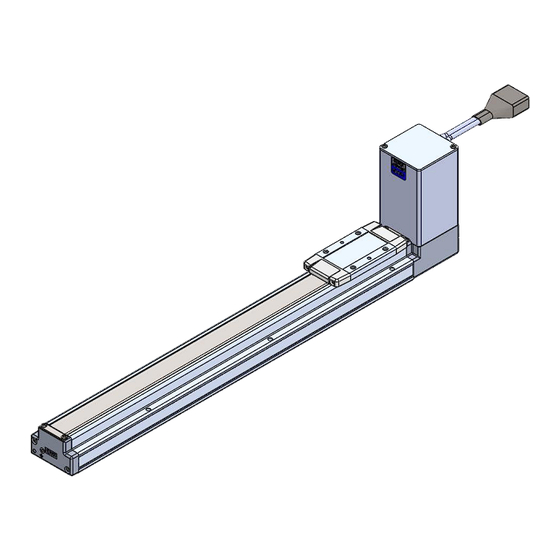
Page 25: Construction
1.5 Construction Comprnent Parts Description Material Note Description Material Note Body Aluminum alloy Anodized Motor cover Aluminum alloy Anodized Rail Guide End cover Aluminum alloy Anodized Belt Band stopper Stainless steel Belt holder Carbon steel Chromating Motor Belt stopper Aluminum alloy Anodized Rubber bushing Table... -
Page 26: Optional Accessories
1.6 Accessories ■ Optional accessories ・Manifold Controller(JXD1-M※) ・Actuator cable (JX‐CP‐D‐※) (P.33 reference) ・Setup software (ACT-Connected) (Please download from SMC website. http://www.smcworld.com/) For details of optional accessories, refer to the Operation Manual "Manifold Controller for Electric Actuator / JXD1-M*", 2.3 How to display unit part number 2.4 Details of options. -
Page 27: 2 Installation And Initial Setting
2 Installation and Initial Setting 2.1 Flow procedure from installation to initial setting Be sure to check the procedure below before use. Procedure 1 Preparation →Item 2.2 ① Checking the contents of the package *:Please confirm that the actuator, accessories, and optional items are present. →Item 2.1... -
Page 28: Check The Contents Of The Package
2.2 Check the contents of the package After unpacking everything, check the description on the label to identify the electric actuator and the number of accessories. If any parts are missing or damaged, please contact your distributor. Product Name and Number Quantity Actuator Electric actuator... -
Page 29: Installation Of Electric Actuators
2.4 Installation of electric actuators Install the electric actuator at the installation location using the following method. (1) Mounting Refer to Electric actuators / Common precautions in Precautions for product specific for information on screws and tightening torques to be used for mounting workpieces and tools and for mounting the actuator. -
Page 30: Wiring And Connection
2.5 Wiring and Connection Prepare the electric actuator LE2FS series and Manifold controller. Connect the Driver unit of Manifold controller and the electric actuator with the actuator cable. 7. Wiring in the instruction manual For wiring details of the manifold controller, please refer to "Manifold controller for electric actuator/JXD1-M*". -
Page 31: 4 Operation Guide
4 Operation Guide For the mechanism of each operation, refer to the following pages of the operation manual "Manifold Controller for Electric Actuators / JXD1-M*". 11.1 Return to Origin 11.2 Positioning Operation 11.4 Response Time to Controller Input Signals 11.5 Interruption method during operation 5... -
Page 32: 7 Setting
7 Setting 7.1 Parameter Setting of operation condition and other conditions of the electric actuator. Caution Write the parameter when the electric actuator is in the stopped condition. Details of parameters The parameters can be set using the setup software “ACT-Connected”. Write column : ◎= Effective immediately after writing to the electric actuator, 〇= Effective when the power supply is turned on again. - Page 33 Default value Setting Lead Description Input range Load LE2FB16 LE2FB25 LE2FB32 Input limit value for Input limit value to Maximum speed ◎ JOG speed The speed of Jogging / Inching is set by this setting. (Unit:1mm/s) each product for each product The acceleration of Jogging / Inching is set by this setting.
-
Page 34: 8 Options
8 Options The optional parts described below are available (sold separately). ・Actuator cable 8.1 Actuator cable JX – CP – D – □ Cable length (L) Cable length(L) 1.5 m 8 mm 10 m 15 m 11 mm 20 m * Produced upon receipt of order Actuator side Driver Unit side... - Page 35 Revision history September 2024: First edition 4-14-1, Sotokanda, Chiyoda-ku, Tokyo 101-0021 JAPAN Tel: + 81 3 5207 8249 Fax: +81 3 5298 5362 URL https://www.smcworld.com Note: Specifications are subject to change without prior notice and any obligation on the part of the manufacturer. ©...
Need help?
Do you have a question about the LE2FB Series and is the answer not in the manual?
Questions and answers