Table of Contents
Advertisement
Quick Links
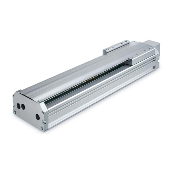
Electric Actuator / High Rigidity Slider Type
《
Applicable models: LEJS100-X400
LEJS100T9 Series
(AC servo motor)
#This manual describes the actuators operation in the "AC servo motor type" or "Motorless type".
#Refer to the manual relevant to the controller being used for full operating instructions.
PRODUCT NAME
AC servo motor
MODEL / Series / Product Number
LEJ Series
・
Motorless
LEJS100N Series
(Motorless)
Doc. No. LEJ*-OMZ0012
》
Advertisement
Table of Contents

Subscribe to Our Youtube Channel
Related Manuals for SMC Networks LEJS100T9 H Series


Summary of Contents for SMC Networks LEJS100T9 H Series
- Page 1 Doc. No. LEJ*-OMZ0012 PRODUCT NAME Electric Actuator / High Rigidity Slider Type 《 ・ 》 AC servo motor Motorless MODEL / Series / Product Number LEJ Series Applicable models: LEJS100-X400 LEJS100N Series LEJS100T9 Series (Motorless) (AC servo motor) #This manual describes the actuators operation in the “AC servo motor type” or “Motorless type”. #Refer to the manual relevant to the controller being used for full operating instructions.
-
Page 2: Table Of Contents
Contents Safety Instructions ................... 2 1. Specification ..................4 1.1 AC servo motor ................4 1.1.1 How to order ..............4 1.1.2 Specification ..............5 1.2 Motorless ..................6 1.2.1 How to order ..............6 1.2.2 Specification ..............7 1.3 Construction ................. 8 2. -
Page 3: Safety Instructions
LEJ series / Slider type Safety Instructions These safety instructions are intended to prevent hazardous situations and/or equipment damage. These instructions indicate the level of potential hazard with the labels of “Caution,” “Warning” or “Danger.” They are all important notes for safety and must be followed in addition to International Standards (ISO/IEC) , and other safety regulations. - Page 4 LEJ series / Slider type Safety Instructions Caution The product is provided for use in manufacturing industries. The product herein described is basically provided for peaceful use in manufacturing industries. If considering using the product in other industries, consult SMC beforehand and exchange specifications or a contract if necessary.
-
Page 5: Specification
1. Specification 1.1 AC servo motor 1.1.1 How to order L E J S 100 - 500 X400 ① ② ③ ④ ⑤ ⑥ ⑦ ⑧ ①Motor type ③Stroke [mm] AC servo motor 1500 1500 *Refer to the applicable stroke table. ④Motor option Without option B... -
Page 6: Specification
1.1.2 Specification Model LEJS100T9□H LEJS100T9□A LEJS100T9□B *1 200,300,400,500,600,800,1000,1200,1500 Stroke [mm] 3000(mm/s Horizontal 5000(mm/s 9800(mm/s Work load [kg] 3000(mm/s Vertical 5000(mm/s 9800(mm/s to 500 2300 1250 Max. speed 501 to 1000 1600 [mm/s] 1001 to 1500 9800 Max. acceleration/deceleration [mm/s Positionimg repeatability [mm] ±0.01 *4 0.05 or less... -
Page 7: Motorless
1.2 Motorless 1.2.1 How to order L E J S 100 - 500 X400 ① ② ③ ②Lead [mm] Applicable stroke table Stroke [mm] Size Manufacturable 1000 1200 1500 stroke range [mm] ● ● ● ● ● ● ● ● ●... -
Page 8: Specification
1.2.2 Specification Model LEJS100NH LEJS100NA LEJS100NB *1 200,300,400,500,600,800,1000,1200,1500 Stroke [mm] 3000(mm/s Horizontal 5000(mm/s 9800(mm/s Work load [kg] 3000(mm/s Vertical 5000(mm/s 9800(mm/s to 500 2300 1250 Max. speed 501 to 1000 1600 [mm/s] 1001 to 1500 9800 Max. acceleration/deceleration [mm/s Positionimg repeatability [mm] ±0.01 *4 0.05 or less... -
Page 9: Construction
1.3 Construction *Motorless type Component parts Maintenance parts/Grease pack Description Material Remarks Apply for Order No. Capacity[g] Body Aluminum alloy GR-S-010 Anodic oxide coating Ball screw Ass'y Linear guidde Ass'y Ball screw Ass'y GR-S-020 Linear guide Ass'y Table Aluminum alloy Anodic oxide coating Side cover Aluminum alloy... -
Page 10: Electric Actuators / Common Precautions
2. Electric actuators / Common precautions 2.1 Wiring/Cables Warning Adjustment, installation, inspection, or wiring changes should be conducted after the power supply to this product has been turned off. Electrical shock, malfunction, or damage can result. Never disassemble the cable. Use only the specified cables. Never connect or disconnect the cable or connector with the power on. -
Page 11: Design/Selection
10. Confirm wiring insulation. Insulation failure (interference with other circuits, poor insulation between terminals, etc.) could introduce excessive voltage or current to the controller or its peripheral devices, causing damage to them. 11. The speed and force may change depending on the cable length, load, and mounting conditions. -
Page 12: Mounting
Do not use the stop signals, the “EMG” of the control- ler and the stop switch on the teaching box, as the emergency stop of the system. The stop signals, “EMG” of the controller and the stop switch on the teaching box, are for decelerating and stopping the actuator. -
Page 13: Handling
When an external guide is used, connect the moving parts of the actuator and the load in such a way that there is no interference at any point within the stroke. Do not scratch or dent the sliding parts of the product tube, piston rod, etc., by striking or grasping them with other objects. - Page 14 Stop operation at once if there are abnormal noises or vibrations. Abnormal noises or vibrations may mean that the product is not properly mounted, and if allowed to continue in this state, damage to the equipment may occur. Never touch the rotating parts of the motor while in operation. Before installing, adjusting, inspecting, or performing maintenance on the product, controller, and related equip- ment, be sure to shut off the power supply.
-
Page 15: Operating Environment
Grounding should be performed near the actuator to shorten the grounding distance. The cross-sectional area of this wire shall be a minimum of 2 mm2. Avoid common grounding with other devices. Other device Actuator Other device Actuator Groundi n g Recommended: Ground Not recommended: Common ground ground... -
Page 16: Maintenance
exposed to harmful gas or liquid. Store in an area that is shaded from direct sunlight and has a temperature and humidity within the specified range (–10 C to 60 C and 35 to 85% no condensation or freezing). Do not apply vibration or impact to the product during storage. 2.6 Maintenance Warning Do not disassemble or repair the product. -
Page 17: Design/Selection
Do not apply liquid, oil, or grease to the lock or the area surrounding it. When liquid, oil, or grease are adhered to the sliding parts of the lock, its holding force will reduce significantly. Any changes in lock sliding performance and condition may cause a lock release malfunction. -
Page 18: Mounting
Products with damage or those missing any compo- nents should not be used. An electric shock, fire, or injury may result. Use only the specified combination between the elec- tric actuator and controller. Failure to do so may cause damage to the actuator or the controller. Be careful not to be hit by workpieces while the actua- tor is moving. -
Page 19: Power Supply
Do not install the product in a place subject to vibra- tions and impacts. It will cause failure or malfunction. Do not mount the controller and its peripheral devices together with a large-sized electromagnetic contactor or no-fuse breaker, which generate vibration, on the same panel. Mount them on different panels, or keep the controller and its peripheral devices away from such a vibration source. -
Page 20: Maintenance
Confirm wiring insulation. Insulation failure (interference with other circuits, poor insulation between terminals, etc.) could introduce excessive voltage or current to the controller or its peripheral devices and damage them. 2.14 Maintenance Warning Perform a maintenance and inspection periodically. Confirm wiring and screws are not loose. Loose screws or wires may cause unintentional malfunction. Conduct an appropriate functional inspection after completing the maintenance and inspection. -
Page 21: Electric Actuator / Slider Type Specific Precautions
3. Electric actuator / Slider type Specific precautions 3.1 Design Caution Do not apply a load in excess of the actuator specification. A product should be selected based on the maximum work load and allowable moment. If the product is used outside of the operating specification, eccentric load applied to the guide will become excessive and have adverse effects such as creating play in the guide, reduced accuracy and reduced product life. - Page 22 10. When mounting the actuator, use screws with adequate length and tighten them with adequate torque. Tightening the screws with a higher torque than the maximum may cause malfunction, whilst tightening with a lower torque can cause the displacement of the mounting position or fall. Mounting the actuator Maximum Mounting the workpiece...
-
Page 23: Precaution On Maintenance
13. When mounting the actuator using the body mounting reference plane, use the pin. And set the height of the pin to be 5mm or more because of R chamfering.(Recommended height:6mm) The surfaces of plates M and E on the ends of the product may slightly protrude from the body mounting reference plane. - Page 24 Revision history No.LEJ*-OMZ0012 Jun / 2021 First edition 4-14-1, Sotokanda, Chiyoda-ku, Tokyo 101-0021 JAPAN Tel: + 81 3 5207 8249 Fax: +81 3 5298 5362 http: / /www.smcworld.com Note: Specifications are subject to change without prior notice and any obligation on the part of the manufacturer. ©...
Need help?
Do you have a question about the LEJS100T9 H Series and is the answer not in the manual?
Questions and answers