Advertisement
Quick Links
LE2Y-TF224-043EN
ORIGINAL INSTRUCTIONS
Instruction Manual
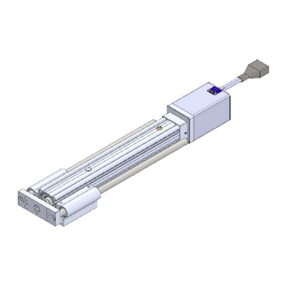
Electric Actuator / Guide Rod type
compatible with manifold controller
Series LE2YG
Motor: Step motor (servo 24 VDC) with Battery-less absolute encoder
The intended use of this Electrical Actuator is to convert an electrical
input signal into mechanical motion.
1 Safety Instructions
These safety instructions are intended to prevent hazardous situations
and/or equipment damage. These instructions indicate the level of
potential hazard with the labels of "Caution," "Warning" or "Danger."
They are all important notes for safety and must be followed in addition
to International Standards (ISO/IEC)
*1)
, and other safety regulations.
*1)
ISO 4414: Pneumatic fluid power — General rules and safety
requirements for systems and their components.
ISO 4413: Hydraulic fluid power — General rules and safety
requirements for systems and their components.
IEC 60204-1: Safety of machinery - Electrical equipment of machines.
Part 1: General requirements.
ISO 10218-1: Robots and robotic devices - Safety requirements for
industrial robots - Part 1: Robots.
• Refer to the product catalogue, Operation Manual and Handling
Precautions for SMC Products for additional information.
• Keep this manual in a safe place for future reference.
Danger indicates a hazard with a high level of risk which, if
Danger
not avoided, will result in death or serious injury.
Warning indicates a hazard with a medium level of risk
Warning
which, if not avoided, could result in death or serious injury.
Caution indicates a hazard with a low level of risk which, if
Caution
not avoided, could result in minor or moderate injury.
Warning
• Always ensure compliance with relevant safety laws and standards.
All work must be carried out in a safe manner by a qualified person in
compliance with applicable national regulations.
• Electromagnetic compatibility
This product is class A equipment intended for use in an industrial
environment. There may be potential difficulties in ensuring
electromagnetic compatibility in other environments due to conducted
as well as radiated disturbances.
• Special products (-X#, -D#) might have specifications that are different
from those shown in the specifications section. Contact SMC for
specific drawings.
2 Specifications
2.1 LE2YG16 series
Model
LE2YG16
Stroke [mm]
30 to 300
Horizontal
17
25
Max. work load
Note 1)
[kg]
Vertical
2.5
5.5
Pushing Force [N]
Note 2) 3) 4)
14~38
27~74
51~141
Speed [mm/s]
15~700
8~350
Acceleration /
Horizontal
10,000 max.
deceleration
Vertical
5,000 max.
2
speed [mm/s
]
Note 5)
Pushing speed [mm/s]
1 to 50
Positioning repeatability [mm]
±0.02
Lost motion [mm]
Note 6)
0.1 max.
Screw Lead [mm]
10
5
Impact/Vibration resistance
50 / 20
2
Note 7)
[m/s
]
Ball screw (LE2YG*D)
Actuation method
Ball screw + Belt (LE2YG*T)
Ball bush bearing (LE2YG*D)
Guide type
Sliding bearing (LE2YG*T)
Operating temperature [℃]
5 to 40
Operating humidity [%RH]
90 or less (no condensation)
□
Motor size [mm]
28
Motor type
Battery-less Absolute (Step motor 24 VDC)
Encoder
Battery-less Absolute
Power supply voltage [V]
24 VDC ±10%
Power consumption [W]
74 max.
Note 8) 9)
Note 10)
Lock Type
Non magnetizing lock
Holding force [N]
25
54
Power consumption [W]
Note9)
4
Power supply voltage [V]
24 VDC ±10%
2.2 LE2YG25 series
Model
LE2YG25
Stroke [mm]
30 to 300
Horizontal
8
26
40
Max. work load
Note 1)
[kg]
Vertical
1
7
15
Note 2) 3) 4)
Pushing Force [N]
36~76
63~122
126~238
Speed [mm/s]
30~900
18~700
9~450
Acceleration /
Horizontal
10,000 max.
deceleration
Vertical
5,000 max.
2
speed [mm/s
]
Note 5)
Pushing speed [mm/s]
1 to 35
Positioning repeatability [mm]
±0.02
Note 6)
Lost motion [mm]
0.1 max.
Screw Lead [mm]
20
12
6
Impact/Vibration resistance
50 / 20
2
Note 7)
[m/s
]
Ball screw (LE2Y*D)
Actuation method
Ball screw + Belt (LE2Y*L/R/T)
Guide type
Sliding bush (Piston rod)
Operating temperature [℃]
5 to 40
Operating humidity [%RH]
90 or less (no condensation)
Motor size [mm]
□
42
Motor type
Battery-less absolute (Step motor 24 VDC)
Encoder
Battery-less absolute
Power supply voltage [V]
24 VDC ±10%
Power consumption [W]
71 max.
Note 8) 9)
Lock Type
Note 10)
Non magnetizing lock
Holding force [N]
10
69
147
Note9)
Power consumption [W]
8
Power supply voltage [V]
24 VDC ±10%
2 Specifications (continued)
2.3 LE2YG32 series
Model
Stroke [mm]
40
Horizontal
30
Max. work load
Note 1)
[kg]
10
Vertical
1
Pushing Force [N]
Note 2) 3) 4)
50~118
4~175
Speed [mm/s]
30~900
Acceleration /
Horizontal
deceleration
Vertical
2
speed [mm/s
]
Note 5)
Pushing speed [mm/s]
Positioning repeatability [mm]
Lost motion [mm]
Note 6)
2.5
Screw Lead [mm]
24
Impact/Vibration resistance
2
Note 7)
[m/s
]
Actuation method
Ball screw + Belt (LE2Y*L/R/T)
Guide type
Sliding bush (Piston rod)
Operating temperature [℃]
Operating humidity [%RH]
90 or less (no condensation)
Motor size [mm]
Motor type
Battery-less absolute (Step motor 24 VDC)
Encoder
Power supply voltage [V]
Note 8) 9)
Power [W]
Note 10)
Lock Type
Holding force [N]
10
Power consumption [W]
Note9)
98
Power supply voltage [V]
Note 1)
Horizontal: Use an external guide (friction coefficient: 0.1 max.).
The maximum value of the work load for the positioning operation. The
actual transported mass and transport speed will vary depending on the
external guide conditions.
Also check the speed / acceleration and duty ratio depending on the
70
payload in the "Speed vs payload graph" in the catalogue.
29
Vertical: Use an external guide (friction coefficient: 0.1 max.) when the
232~452
rod is directed upward or a radial load is applied to the rod.
5~225
The maximum value of the workload for the positioning operation. The
actual transported mass and transport speed will vary depending on the
external guide conditions.
Also check the speed / acceleration and duty ratio depending on the
payload in the "Speed vs payload graph" in the catalogue.
Set the acceleration / deceleration to: Horizontal: 10,000 [mm/s
2
Vertical: 5,000 [mm/s
] max.
Note 2)
Pushing force accuracy is ±20% (F.S.).
Note 3)
The setting range for the "Pushing force" is from 25% to 45% (LE2YG16),
3
25% to 50% (LE2YG25) and 30% to 70% (LE2YG32).
The pushing force setting range varies depending on the duty ratio and
pushing speed. Refer to the catalogue for the "Thrust Conversion Graph".
Note 4)
Speed and thrust vary depending on the cable length, load, installation
conditions, etc. If the cable length exceeds 5 m, the speed / thrust will
decrease by up to 10% for every 5 m (max. 20% reduction for 15 m).
Note 5)
"Pushing speed" is the allowable speed for the pushing operation. When
transporting and pushing a workpiece, operate the actuator according to
the "Vertical Load capacity" or less.
Note 6)
This is a reference value for correcting an error in reciprocal operation.
Note 7)
Impact resistance: In a drop impact test, no malfunction occurred in the
axial and perpendicular direction to the lead screw. The test was
performed with the actuator in the initialized state.
Vibration resistance: 45 to 2000 Hz for 1 sweep, no malfunction occurred
in the an axial and perpendicular direction to the lead screw. The test was
performed with the actuator in the initialized state.
Note 8)
Indicates the maximum power during operating including the controller.
Use this value when selecting the power supply capacity.
284
Note 9)
For an actuator with lock, add the power consumption for the lock.
Note 10) Only applies to actuators supplied with a lock.
2 Specifications (continued)
2.4 Actuator weight [kg]
LE2YG16 series
LE2YG32
Series
30 to 300
Stroke
30
50
90
100
Weight
1.01
Lock
11
24
44
80~189
156~370
296~707
Series
24~800
12~400
6~200
Stroke
30
10,000 max.
Weight
1.02
Lock
5,000 max.
1 to 30
Series
Stroke
30
±0.02
Weight
1.05
0.1 max.
Lock
16
8
4
Series
50 / 20
Stroke
30
Weight
1.06
Ball screw (LE2Y*D)
Lock
LE2YG25 series
5 to 40
Series
Stroke
30
50
Weight
1.92
2.11
□
56.4
Lock
Battery-less absolute
Series
24 VDC ±10%
Stroke
30
50
Weight
1.93
2.14
93 max.
Lock
Non magnetizing lock
108
235
431
Series
8
Stroke
30
50
Weight
2.00
2.19
24 VDC ±10%
Lock
Series
Stroke
30
50
Weight
2.01
2.22
Lock
LE2YG32 series
Series
Stroke
30
50
Weight
3.20
3.46
Lock
Series
Stroke
30
50
2
] max.,
Weight
3.20
3.47
Lock
Series
Stroke
30
50
Weight
3.32
3.58
Lock
Series
Stroke
30
50
Weight
3.32
3.59
Lock
LE2YG16MD*H (with In-line motor)
50
100
150
200
1.15
1.38
1.69
1.86
0.19
LE2YG16LD*H (with In-line motor)
50
100
150
200
1.15
1.32
1.63
1.78
0.19
LE2YG16M*H (with Parallel motor)
50
100
150
200
1.19
1.43
1.73
1.91
0.19
LE2YG16L*H (with Parallel motor)
50
100
150
200
1.19
1.37
1.67
1.83
0.19
LE2YG25MD*H (with In-line motor)
100
150
200
250
300
2.44
2.89
3.22
3.57
3.83
0.34
LE2YG25LD*H (with In-line motor)
100
150
200
250
300
2.39
2.85
3.10
3.43
3.67
0.34
LE2YG25M*H (with Parallel motor)
100
150
200
250
300
2.52
2.97
3.30
3.65
3.91
0.34
LE2YG25M*H (with Parallel motor)
100
150
200
250
300
2.47
2.93
3.18
3.51
3.75
0.34
LE2YG32MD*H (with In-line motor)
100
150
200
250
300
4.01
4.77
5.32
5.81
6.26
0.63
LE2YG32LD*H (with In-line motor)
100
150
200
250
300
3.86
4.61
5.03
5.54
5.94
0.63
LE2YG32M*H (with Parallel motor)
100
150
200
250
300
4.13
4.89
5.45
5.94
6.39
0.64
LE2YG32L*H (with Parallel motor)
100
150
200
250
300
3.98
4.73
5.16
5.67
6.07
0.64
Page 1 of 3
Advertisement

Related Manuals for SMC Networks LE2YG Series


Summary of Contents for SMC Networks LE2YG Series
- Page 1 LE2Y-TF224-043EN 2 Specifications 2 Specifications (continued) 2 Specifications (continued) ORIGINAL INSTRUCTIONS 2.1 LE2YG16 series 2.3 LE2YG32 series 2.4 Actuator weight [kg] LE2YG16 series Model LE2YG16 Model LE2YG32 Instruction Manual Series LE2YG16MD*H (with In-line motor) Stroke [mm] 30 to 300 Stroke [mm] 30 to 300 Stroke Horizontal...
- Page 2 7 Maintenance actuator and its peripheral devices are within the range of the • When using an auto switch with the guide rod type LE2YG series, the voltage from power and high voltage cables close to the signal line. 7.1 General Maintenance specifications.
- Page 3 LE2Y-TF224-043EN 7 Maintenance (continued) • Following any maintenance, always perform a system check. Do not use the product if any error occurs, as safety cannot be assured if caused by any un-intentional malfunction. 7.3 Appearance Check • The following items should be visually monitored to ensure that the actuator remains in good condition and there are no concerns flagged;...
Need help?
Do you have a question about the LE2YG Series and is the answer not in the manual?
Questions and answers