
Related Manuals for jurop VL 7-40


Summary of Contents for jurop VL 7-40
- Page 1 VL 7-40 ORIGINAL INSTRUCTIONS INSTALLATION USE AND MAINTENANCE MANUAL Rev. 06 07-01-2021...
- Page 2 2021 – Jurop – Azzano Decimo (PN) Reproduction, electronic storage and dissemination, even partial, are prohibited. Jurop reserves the right to modify the products described in this manual without prior notice. Any product names mentioned herein are the trademarks of their respective owners.
-
Page 3: Table Of Contents
. 06 – 07-01-2021 INSTALLATION USE AND MAINTENANCE MANUAL VL 7-40 Contents General warnings pag. Introduction Spare part request Warranty terms and conditions Technical data pag. Arrangements Dimensions VL Performances Sound Power Lobes type Lubrication Safety and accident prevention pag. -
Page 4: General Warnings
. 06 – INSTALLATION USE AND MAINTENANCE MANUAL VL 7-40 07-01-2021 1. General warnings 1.1. Introduction 1.2. Spare part request • This booklet contains the necessary instructions for a correct • Use only genuine spare parts for maintenance and repairs. To... -
Page 5: Technical Data
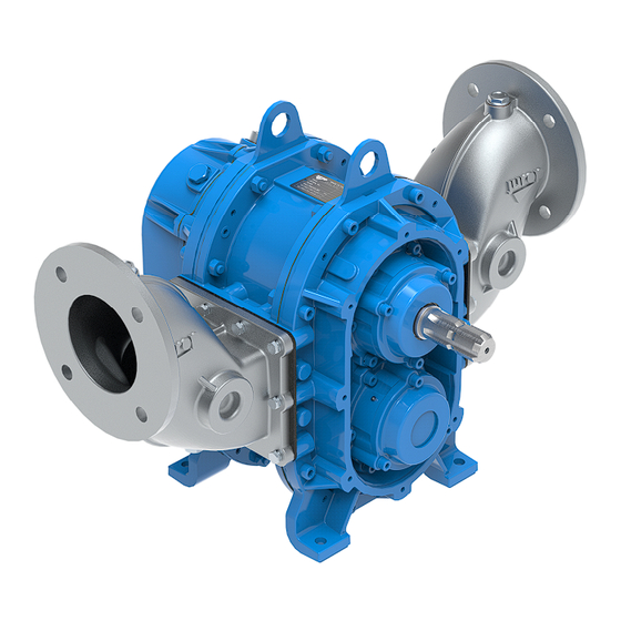
07-01-2021 INSTALLATION USE AND MAINTENANCE MANUAL VL 7-40 2 Technical data • Positive displacement rotary lobe selfpriming pumpe. Flow rate varies proportionally to the rotation speed. • Two counter rotating lobes transfer from the inlet to the outlet the pumped media drawn into the pockets formed between the lobes and the pump housing. -
Page 6: Dimensions
. 06 – INSTALLATION USE AND MAINTENANCE MANUAL VL 7-40 07-01-2021 2.2. Dimensions VL 7 462.5 VL 14 462.5 VL 20 462.5 VL 27 462.5 VL 40 462.5 WEIGHT DN80 PN6 -0.009 VL 7 Ø 90 35 g6 G 1 ½”... -
Page 7: Vl Performances
. 06 – 07-01-2021 INSTALLATION USE AND MAINTENANCE MANUAL VL 7-40 2.3. VL Performances FLOW POWER VL 7 VL 14 VL 20 Jurop SpA . +39 0434 636811 F . +39 0434 636812 http://www.jurop.it Via Crosera n° 50 7 / 32 e-mail: info@jurop.it... -
Page 8: Sound Pressure Level
. 06 – INSTALLATION USE AND MAINTENANCE MANUAL VL 7-40 07-01-2021 VL 27 VL 40 Conditions: Water, Density 1000 kg/m3 - Viscosity 1cSt. Actual performance may vary of 5%. VL 7 VL 14 VL 20 VL 27 VL 40 TECHNICAL DATA... -
Page 9: Lobes Type
. 06 – 07-01-2021 INSTALLATION USE AND MAINTENANCE MANUAL VL 7-40 2.5. Lobes type • Pump lobes can be available in the following versions: NBR, FKM, EPDM, Polyurethane and XNBR. • Check the chemical compatibility of the matter to be conveyed with the lobes’... -
Page 10: Safety And Accident Prevention
. 06 – INSTALLATION USE AND MAINTENANCE MANUAL VL 7-40 07-01-2021 3. Safety and accident prevention Signals indicating specific parts of the machine for an easier Warning: Carefully apply these prescriptions. identification, such as: greasing points, oil tanks, etc. - Page 11 – 07-01-2021 INSTALLATION USE AND MAINTENANCE MANUAL VL 7-40 • To prevent anomalies in running, above all when inflammable liquids are to be conveyed, keep pressure at the suction flange sufficiently high in order not to prime the cavitation phenomenon.
-
Page 12: Installation
. 06 – INSTALLATION USE AND MAINTENANCE MANUAL VL 7-40 07-01-2021 4. Installation Main components legend VL Housing Front / Rear bench Rear oilt tank Wearproof plate (with handling hole) Lubricant fill up plug / Ventil plug Lubricant level control plug... -
Page 13: Pump Mounting - Drive Connection
. 06 – 07-01-2021 INSTALLATION USE AND MAINTENANCE MANUAL VL 7-40 The suction of solid parts of excessive dimensions Follow the instructions of the cardan shaft’s must be avoided: otherwise, the sudden blocking manufacturer. of the pump may cause the breakage of the transmission devices. - Page 14 . 06 – INSTALLATION USE AND MAINTENANCE MANUAL VL 7-40 07-01-2021 C) Hydraulic Drive • Motor piping: with a nominal diameter at least equal to that of the motor ports The diameter of the motor inlet pipe is always smaller than the discharge.
-
Page 15: Precautions When Starting The System
. 06 – 07-01-2021 INSTALLATION USE AND MAINTENANCE MANUAL VL 7-40 5. Starting-up instructions 5.1. Oil level checking • Frost hazard: protect the pump and its connections from freezing. The ice pieces coming off the piping could cause damages if they get into the pumping chamber. -
Page 16: Maintenance
. 06 – INSTALLATION USE AND MAINTENANCE MANUAL VL 7-40 07-01-2021 6. Maintenance 6.1. Ordinary maintenance • Check the proper functioning of the seals. The presence of liquid means damaged seals. If leakages are detected, it is necessary to replace the seals as soon as possible. - Page 17 – 07-01-2021 INSTALLATION USE AND MAINTENANCE MANUAL VL 7-40 Follow the safety prescriptions as described in Cap. “Safety and accident prevention”. Preliminary steps (instructions common to all models) • Refer to the spare parts catalogue of the individual pumps for correspondence.
- Page 18 . 06 – INSTALLATION USE AND MAINTENANCE MANUAL VL 7-40 07-01-2021 • In case of VL 27: lift the assembly by holding it by the ends of the End plate- housing and wearplate group plate. Knock on the protective piece, using the inertia of the system.
- Page 19 – 07-01-2021 INSTALLATION USE AND MAINTENANCE MANUAL VL 7-40 Shaft– lobe group Assemble of the pump housing – lobes – end plate VL 7-14-20 • Check that the O-rings of the axle are in the correct position (Fig. • After having lubricated the axis (A), assemble the axis-lobe units 6.9).
- Page 20 . 06 – INSTALLATION USE AND MAINTENANCE MANUAL VL 7-40 07-01-2021 Assemble of the pump housing – lobes – end plate VL 27-40 • Insert the spacer (C), safety ring (D) and ring (E). • For fixing the self-locking ring, insert a pin in between the gears (K) •...
- Page 21 The servicing operations which require the pump to be completely disassembled must be performed at a Service Centre authorised by JUROP. The servicing operations which require the pump to be completely disassembled must be performed at a Service Centre authorised by JUROP.
-
Page 22: Malfunctions: Troubleshooting
. 06 – INSTALLATION USE AND MAINTENANCE MANUAL VL 7-40 07-01-2021 7. Malfunctions: troubleshooting PROBLEMS THE PUMP DOES NOT DELIVER Cause Solution • Excessive suction depth • Reduce the suction depth • Undersized intake line components • Increase piping diameters •... - Page 23 CODE C525233051 VL 7 CODE C51… VL 14 CODE C52… VL 20 CODE C53… Jurop SpA . +39 0434 636811 F . +39 0434 636812 http://www.jurop.it Via Crosera n° 50 23 / 32 e-mail: info@jurop.it 33082 Azzano Decimo, PN (Italia)
- Page 24 SCREW TCEI 8.8 M8X20 ZINC. Various codes ADD ONE PCS IN CASE OF DOUBLE SPLINED AXIS MODEL 4026121406 SCREW TCEI 8.8 M8X30 ZINC. Jurop SpA . +39 0434 636811 F . +39 0434 636812 http://www.jurop.it Via Crosera n° 50 24 / 32 e-mail: info@jurop.it...
- Page 25 07-01-2021 VL 27 PICTURE SHOWS VL 27 WITH SPLINED SHAFT CODE C545033050 VL 27 CODE C54… Jurop SpA . +39 0434 636811 F . +39 0434 636812 http://www.jurop.it Via Crosera n° 50 25 / 32 e-mail: info@jurop.it 33082 Azzano Decimo, PN (Italia)
- Page 26 WASHER GROWER 10 ZINC. 4026351505 WASHER M8 ZINC. 4026359003 WASHER 21.5X26X1.5 4026359006 WASHER 13.5X18X1.5 Jurop SpA . +39 0434 636811 F . +39 0434 636812 http://www.jurop.it Via Crosera n° 50 26 / 32 e-mail: info@jurop.it 33082 Azzano Decimo, PN (Italia)
-
Page 27: Spare Part Data Sheet - Vl
07-01-2021 VL 40 PICTURE SHOWS VL 40 WITH SPLINED SHAFT CODE C555033050 VL 40 CODE C55… Jurop SpA . +39 0434 636811 F . +39 0434 636812 http://www.jurop.it Via Crosera n° 50 27 / 32 e-mail: info@jurop.it 33082 Azzano Decimo, PN (Italia) - Page 28 WASHER GROWER 8 ZINC. 4026350708 WASHER GROWER 10 ZINC. 4026351505 WASHER M8 ZINC. 4026359003 WASHER 21.5X26X1.5 Jurop SpA . +39 0434 636811 F . +39 0434 636812 http://www.jurop.it Via Crosera n° 50 28 / 32 e-mail: info@jurop.it 33082 Azzano Decimo, PN (Italia)
-
Page 29: Spare Part Data Sheet - Vl
. 06 – SPARE PART DATA SHEET VL HDR 07-01-2021 VL 7-40 HYD Pos. Code Description Q.ty Pos. Code Description Q.ty 1612501600 HYD BOX 4026121303 SCREW TCEI 8.8 M6X12 ZINC. 16420139E0 HYD BOX PROTECTION 4026171304 STUD SCREW 8.8 M14X40 ZINC. -
Page 30: Spare Part Data Sheet - Vl
VENT PLUG 3/8" 40222RPB00 GASKET 4023100155 BEARING 6210 Note. Recommended gear oil: SAE 80W/90. Oil capacity: approximately 0,6 l. Jurop SpA . +39 0434 636811 F . +39 0434 636812 http://www.jurop.it Via Crosera n° 50 30 / 32 e-mail: info@jurop.it... - Page 31 . 06 07-01-2021 Jurop SpA . +39 0434 636811 F . +39 0434 636812 http://www.jurop.it Via Crosera n° 50 31 / 32 e-mail: info@jurop.it 33082 Azzano Decimo, PN (Italia)
- Page 32 33082 Azzano Decimo, PN (ITALY) Tel. +39 0434 636811 Fax. +39 0434 636812 http://www.jurop.it e-mail: info@jurop.it Jurop SpA reserves the right to modify the products described in this manual without prior notice. Jurop SpA . +39 0434 636811 F . +39 0434 636812 http://www.jurop.it Via Crosera n°...
Need help?
Do you have a question about the VL 7-40 and is the answer not in the manual?
Questions and answers