
Subscribe to Our Youtube Channel
Related Manuals for Regulus IR 14 RTC


Summary of Contents for Regulus IR 14 RTC
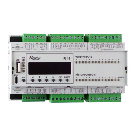
- Page 1 Instruction Manual IR 14 Heating Controller V.: IR14 RTC Valid for FW 1.0.5.0 IR 14 RTC...
-
Page 2: Table Of Contents
Technical Description of IR 14 Heating Controller ................... 3 How to operate IR 14 Controller .................... 3 1.1. Basic User Menu .......................... 4 User Menu .......................... 1 1 2.1. Heating Zones .......................... 11 2.2. HVAC Unit ............................ 12 2.3. Time programs .......................... 13 2.4. OTC curves ............................ 13 2.5. -
Page 3: Technical Description Of Ir 14 Heating Controller
Technical Description of IR 14 Heating Controller Variant IR14 RTC IR 14 Heating Controller (var. IR14 RTC) is a controller of heating systems with a RTC heat pump and a solar thermal system. The controller can handle up to 6 heating zones with a mixing valve, DHW heating by a heat pump, DHW heating by a switched heat source, it can also control auxiliary heat sources (electric or gas-fired boilers) and a HRV unit. -
Page 4: Basic User Menu
The keys , are used to browse in the menu. In order to edit a parameter, press ENTER and a cursor appears on the parameter. The values of numeric parameters can be increased/decreased by pressing / keys. Selection parameters (e.g. ON/OFF) are chosen by pressing keys , . - Page 5 4 – current and desired heating water temperature for the zone Possible operating states indicated on the service display and their equivalent in the controller web interface are shown below: Displayed on the service display Displayed on the web interface off by service DISABLED BY SERVICE off by user...
- Page 6 2 – system ON 3 – ON = solar pump running 4 – marking of the currently heated DHW storage tank 5 – DHW storage tank 1, current temp (desired in solar heating) 6 – DHW storage tank 2, current temp (desired in solar heating) 7 –...
- Page 7 Heat Pump, cascade display: 1 – state of heat pump No.1, No. 2, No. 3 In this section, heat pump states are shown that are enabled on the Service level. The states can be following: OFF - service - heat pump is turned off by a heating engineer ...
- Page 8 rebooting - heat pump is blocked by min. time between 2 compressor starts heating - heat pump is heating your home RC blocking - heat pump is blocked by Ripple control vol.flow control - heat pump’s circulation pump is running ...
- Page 9 2 – desired and real flow temp. of OT source 3 – state of communication with OT source: OK / error Display with firmware version and release date: Controller in factory setting: If the display shows the text above with warning about the controller being reset to default settings, it is necessary to contact a service provider who shall set the respective controller parameters.
- Page 10 Selection of the desired setting (menu): While in MENU, use arrow keys , to select the desired setting: Settings < for user > – user setting of zones, DHW heating and other parameters. Settings < add.modules > - display of basic information on additional modules, if present. Settings <...
-
Page 11: User Menu
User Menu The keys , enable browsing in the User Menu, and the selected item can be entered by pressing ENTER. 2.1. Heating Zones Heating Zone basic settings T comfort (°C) .... Setting comfort temperature in zone (desired room temperature). T setback (°C) .... -
Page 12: Hvac Unit
2.2. HVAC Unit HVAC Zone basic settings comfort (%) ....HRV unit power settings during a "comfort“ mode from 15 to 100%. setback (%) ....HRV unit power settings during a "setback“ mode from 15 to 100%. During a day, the controller switches the desired HVAC unit power by the preset time schedule (adjustable from the web interface only). -
Page 13: Time Programs
2.3. Time programs Time programs can be set either for separate days, or in blocks Mo-Fr and Sa-Su. When the program is being set for separate days, there are 2 transitions from Comfort to Setback and 2 from Setback to Comfort for each day. When the program is being set in blocks, there are similarly 2 transitions for the blocks Mo-Fr and Sa-Su. -
Page 14: Heat Pump Errors
2.6. Heat pump errors In this menu all heat pump errors can be reset (by changing the option Reset all errors to Yes). By pressing the down arrow, the HP error log can be browsed. 1 – error serial number (1 – 10) 2 –... -
Page 15: Setting Temperatures For Thermal Store
Anti Legionella function Anti-Legionella function is designed for thermal “disinfection” of hot water storage tanks, primarily against Legionella bacteria. When this function is ON, the hot water storage tank heats up to at least 65°C once in a week, at a preset time on a preset day. Heating is switched off either when this temperature is reached, or after two hours from switching this function on, disregarded of the temperature. -
Page 16: Operating Data
2.13. Operating data All temperatures, pressure, most important heat pump temperatures and states and controller output values are displayed here for the user. An E letter at the end of the temperature sensor line means that the given temperature sensor is outside its permitted working range and it is necessary to check this sensor and its connection and correct the fault. -
Page 17: Regulusroute - Parameters Of Connection With The Service
2.16. RegulusRoute - parameters of connection with the service RegulusRoute service enables remote access to the Controller avoiding the need to use a public IP address. If you wish to have this service configured, kindly contact Regulus. Regulus Route ... displays whether the service is on. -
Page 18: Additional Modules
Additional modules In the basic menu, when add.modules are selected, user information on additional modules (if present) can be viewed. Fire Module Temperature (°C) ..Fireplace flow temperature. Damper (%) ....Display of how opened is the damper of the air supply to the fireplace. DHW pump .... -
Page 19: Web Interface
Web interface The controller involves an integrated website showing a heating system overview and user settings. For its website access, the controller shall be connected to a LAN or directly to a PC using a network cable. The parameters for the network connection (IP address, gateway address and subnet mask) can be found in the controller information by pressing the DISP key. -
Page 20: Home Screen (Home)
4.1. Home screen (HOME) The home screen contains basic information about the two heating zones, DHW heating, recirculation and Heat Recovery Ventilation zone. Service-enabled zones are highlighted in colour and can be controlled. Service-deactivated zones are only shown and cannot be controlled. - Page 21 The home page displayed in a computer browser The home page displayed in the IR Client mobile app...
- Page 22 Tiles for space and DHW heating The ON/OFF button is Clicking on this button will open used to turn the zone on the detailed zone settings. or off on user level. Sun-Moon (comfort- setback). The snow- flake indicates active cooling. Information about the current zone Heating...
-
Page 23: Display Of The Diagram (Diagram)
4.2. Display of the Diagram (DIAGRAM) Schematic representation of your hydraulic connection with a clear display of important quantities, states and information. The diagram should therefore always correspond to your current hydraulic connection. To get a proper presentation in the mobile application, it is necessary to rotate the device to landscape view. -
Page 24: Heating Zone Menu (Heating)
4.3. Heating zone menu (HEATING) The menu is used to select the settings of one of the heating zones (Zones 1 to 6), to set the thermal store heating (ThSt Zone) and holiday mode settings (Holidays), or to set the pool heating (Pool heating - if controlled by the controller). - Page 25 When the outdoor temperature drops below -2 ° C, comfort mode is automatically activated. This function is designed to save energy so that it does not switch on an auxiliary bivalent source in the event of a sudden request for a higher zone temperature. This function can be switched off on the service level.
- Page 26 In winter mode, zone heating is switched on (the zone is heated to the required temperature according to the current comfort/setback mode). In summer mode, zone heating is switched off.
- Page 27 OTC curves settings The purpose of weather compensating control is to reduce the heating water temperature when the outdoor temperature rises (and vice versa). This can effectively reduce overheating or underheating of dwelling space and also increase the efficiency of system operation. From the point of view of energy savings and thermal comfort in living rooms, it is more advantageous to heat the building to the required room temperature with a lower heating water temperature for a longer time than with a higher heating water temperature for a shorter time.
- Page 28 Building overheating at temperatures above zero If a building overheats at an outdoor temperature above zero, the heating water temperature shall be reduced with the minus button. The graph shows that the heating water temperature will be adjusted mainly at temperatures above zero. Building underheating at temperatures above zero If a building underheats at an outdoor temperature above zero,...
- Page 29 Building underheating at temperatures below zero If a building underheats at an outdoor temperature below zero, the heating water temperature shall be increased with the plus button. The graph shows that the heating water temperature will be adjusted mainly at temperatures below zero.
- Page 30 Cooling settings With the ON/OFF button, cooling can be switched on by the user and the desired room temperature can be set (corresponding to the comfort temperature for heating). Transition cooling means that cooling is only active if the outdoor temperature exceeds the set limit (Transition outdoor temp.).
-
Page 31: Zone Dhw (Domestic Hot Water)
4.4. ZONE DHW (Domestic hot water) DHW heating is divided into DHW-HP (DHW heating by a heat pump) and DHW-E (DHW heating by auxiliary heat source). If the hot water recirculation function is switched on, there is also a tile CIRCULATION. 4.4.1. -
Page 32: Sources Menu (Sources)
The desired temperatures from an auxiliary heat source should be set lower than the desired temperatures from the heat pump to avoid unnecessary switching of the DHW-E source. The time program setting is identical to the time program setting in zones 1 - 6. 4.4.3. - Page 33 4.5.1. Heat pump The heat pump can be switched on or off by the user with the ON/OFF button. Heat pump operation Statistics Current status of the heat pump, information statistics - operating heating by heat pump compressor operation (for hours and number of –...
- Page 34 4.5.2. Solar heating The solar circuit can be switched on or off with the ON/OFF button. The solar circuit allows heating of up to three solar appliances. Current temperature of solar collectors Solar pump operation information Current temperature: temperature measured by the hot water storage tank sensor.
- Page 35 4.5.3. Fire, solid fuel boiler The heat source can be switched on or off with the ON/OFF button. Control of solid-fuel boiler pump, or possibly fireplace combustion-air damper. The Solid fuel boiler function requires an add-on module and needs to be enabled on the service level. Status of boiler pump and air supply damper - Current measured values on displayed as a percentage of air supply opening or...
- Page 36 4.5.4. Switched auxiliary heat sources (ON/OFF Source, ON/OFF Source 2) The ON/OFF source is intended as an auxiliary source for heating or as a backup source in the event of a heat pump failure. In most cases, this source will be an electric heating element located in the thermal store or an electric boiler connected in series with the heat pump.
- Page 37 fledged heating source in the event of a heat pump failure, which would lead to increased costs for both space and hot water heating. 4.5.5. OpenTherm auxiliary source The heat source can be switched on or off by the user with the ON/OFF button. Settings page intended for modulated sources equipped with OpenTherm communication.
- Page 38 4.5.6. Auxiliary source 0-10V The heat source can be switched on or off by the user with the ON/OFF button. Settings page intended for sources modulated by 0-10V voltage signal. Measured temperature at the control Status of auxiliary heat source and sensor and desired temperature for the auxiliary heat source.
-
Page 39: Menu With Other Settings (Others)
They can only be changed if there is another SMTP server on the network that blocks the use of the default settings. In this case, the function reports an error and it is necessary to contact the Regulus service department. - Page 40 4.6.5. Weather forecast The weather forecast can be switched on or off with the ON/OFF button. The Weather forecast function is used to display the current weather and the forecast for the next day. Weather information is obtained from the server yr.no. After turning on the weather forecast, you must enter the state, region, and location on the settings page to refine the information.
- Page 41 4.6.8. Ventilation unit The zone can be switched on or off by the user with the ON/OFF button. Display current outdoor Display of the current zone status and the temperature output status of the summer bypass flap. Ventilation unit Setting the Ventilation unit output Comfort ......
-
Page 42: Menu With Access To Manuals (Manuals)
Cooling function The Cooling function can be switched on or off with the ON/OFF button. In this section it is possible to enter the required cooling water temperature and set the cooling parameters. Cooling is determined by outdoor temperature means that cooling to the HVAC unit will only start if the outdoor temperature is above the set outdoor temperature for switching on cooling. - Page 43 Service Guide for IR 14 Controller Variant IR14 RTC Valid for FW: 1.0.5.0 Controller Wiring ............................ 4 4 1.1 List of output optional functions ............................. 45 Technical Data for IR 14 Controller...................... 4 6 Technical Data for OpenTherm Module ...................... 4 6 Controller Installation .......................... 4 7 Service Menu ............................. 4 9 ...
-
Page 44: Controller Wiring
Controller Wiring Warning: Controller wiring may be performed by a qualified person only. Layman adjustments of the controller may cause damage to parts of the system. -
Page 45: List Of Output Optional Functions
1.1 List of output optional functions LIST OF OPTIONAL FUNCTIONS FOR OUTPUTS F2‐F6 1 On/Off source 2 2 UNI function 1 3 DHW recirculation 4 solid‐fuel boiler pump 5 zone 2 pump 6 zone 2 valve opening 7 zone 2 valve closing 8 cooling 1 9 UNI function 2 10 HP1 pump 11 SOL pump 12 2nd solar consumer valve 13 3rd solar consumer valve 14 DHW heating from ThSt 15 Alarm 16 17 ... -
Page 46: Technical Data For Ir 14 Controller
Technical Data for IR 14 Controller Power supply Voltage ............. 24 V DC ± 5% Power consumption .......... max. 10 W Installation ............power distribution box, DIN rail (9 modules) IP rating ............IP 20 Working temperatures ........-20 to +55 °C Relative humidity .......... -
Page 47: Controller Installation
Controller Installation The Controller is designed to be installed on DIN rail in a power distribution box. It may be installed by a properly qualified person only!! The Controller and power supply unit shall be installed next to each other (see wiring fig.). The recommended min. - Page 48 translation of terms used in wiring diagrams: Jistič fáze MAR = Circuit braker for the IR14 controller, Module = Module, Zdroj = Power supply, Tepelné čerpadlo = Heat pump, Oběhové čerpadlo = Circulation pump of the heat pump, Kotel s opentherm = Boiler with opentherm Boiler wiring diagram with OpenTherm communication The address switch of the OT module shall be set to pos.
-
Page 49: Service Menu
Service Menu Warning: Service menu is intended for a specialist only. Layman adjustments of parameters in the Service menu may lead to damage to parts of the heating and solar thermal system. In the Basic menu, the Service option shall be selected in order to enter this section, and confirmed by ENTER. -
Page 50: Settings For Zones 1 And 2
5.1. Settings for Zones 1 and 2 zone (on/off) ....Service switch on/off the zone. When a zone is switched off on service level, there is no zone frost protection function. max.t to zone (°C) ..Setting max. heating water temperature into a zone. The desired temperature calculated by Controller will not exceed this set value. -
Page 51: Settings For Heat Recovery Ventilation (Hvac) Unit
calculation temps. outdoor (°C) ........Outdoor calculation temperature depending on the location of the building to be heated. 5.2. Settings for heat recovery ventilation (HVAC) unit HVAC unit (on/off) ..Switching on/off the zone on service level. signal min (V) ..... Minimum signal level (corresponds to 0% performance value). signal max (V) .... - Page 52 Solar (active/off) ..Switching on solar zone. sol.cons. 1,2 (active/off) ........Switching on separate tanks in solar circuit. Solar consumer 1, 2 sensor (sensor list) ... Choice of temperature sensor in a solar tank. diff. on (°C) ....Difference to switch on heating from solar circuit. Difference between solar collector and temperature sensor set in parameter sensor.
- Page 53 number is selected in parameter Solar consumer number for collector/tank cooling. If the temperature in this tank exceeds the preset critical tank temperature, collector cooling is stopped. on (active / off) ... Switching on the function of collector cooling. crit.storT (°C) ..... Setting a critical tank temperature. Collector cooling by heating the tank selected in parameter Solar consumer number for collector/tank cooling may run only until the tank temperature set by this parameter is reached.
-
Page 54: Heat Pump Settings
solar PWM pump (on/off) ........Switching on the PWM pump function. set. differ. (K) ..... Desired temperature difference between solar collector and storage tank. purge time (mm:ss) ........Purging time (time when pump is running at maximum power after switching on). PWM profile (sol., heat.) ........ - Page 55 RC for heat. (yes/no) ........Ripple control for heating. With no the heat pump runs disregarded of the Ripple control signal. Control sensors for HP cascade on (sensor list) ..Control sensor to switch on a HP/cascade. off (sensor list) ..Control sensor to switch off a HP/cascade. For a cascade, the default choice HP1 return is not recommended.
-
Page 56: Heat Pump 1 Operating Data
external blocking input (sensor list) ........Setting the terminal to which an input used for blocking the heat pump externally can be connected. It is possible to select any free sensor input to IR or inputs from the add-on digital input module (if present). Heat pump 1 settings It is necessary to use the web interface to set other heat pumps in the cascade. -
Page 57: Hp Blocking
Evapor.1 t. (°C) ..Temperature of discharged air Outdoor t. (°C) ... Outdoor temp. to HP (air source HPs only) Evapor. t. (°C) .... HP evaporation temp. Suction t. (°C) .... HP compressor intake temp. Superheat (°C) ... Superheat at HP compressor suction Evap.press. -
Page 58: Settings For An Auxiliary Source With Opentherm
5.9. Settings for an auxiliary source with OpenTherm source (active/off) ..Switching on an auxiliary source on service level. DHWE heating (yes/no) ........If yes, OT boiler is started simultaneously with DHW-E zone demand. DHW-E output continues to be active and can be used to switch terminals in boilers that require this. -
Page 59: Settings For Dhw Heating By A Heat Pump (Dhw-Hp)
Ripple c. (yes/no) ........Settings for 0-10V source control by Ripple control signal. DHWE heating (yes/no) ........If yes, 0-10V source is started simultaneously with DHW-E zone demand. DHW- E output continues to be active and can be used to switch terminals in boilers that require this. -
Page 60: Sensor Management
5.14. Sensor management IN (-) ......The terminal number to which the temperature sensor is connected. Option 1 indicates a sensor is not used and options 2 to 9 correspond to terminals C2 to connected (yes/no) ... No option shall be selected in case no temperature sensor is connected (to avoid the program reporting an error when the sensor is disconnected). -
Page 61: Fireplace
website password reset (no/reset) ........Selecting reset will reset the website service level username and password to default values. 5.16. Fireplace: A fireplace or solid fuel boiler can be controlled directly via one of the optional outputs on terminal block F of the IR controller or via an add-on module. - Page 62 It is obvious from the picture that the Delay function can delay signal from thermostat and diff. thermostat functions, the Overrun function can hold disconnection (switching off) from thermostat, diff. thermostat and delay functions. The Timer function is superior over all the preceding functions. Basic settings UNI function active (on/off) Switching on the universal function.
-
Page 63: Addresses Of Cib Modules
Timer A simple timer with two time periods. on 1 (hh:mm) ..... The first period switch-on time. off 1 (hh:mm) ..... The first period switch-on off time. on 2 (hh:mm) ..... The second period switch-on time. off 2 (hh:mm) ..... The second period switch-off time. reset state of T1&T2 with every start of the period of the program ........ -
Page 64: Regulusroute
Serial number .... Controller serial number (information only). 5.20. RegulusRoute RegulusRoute service enables remote access to the Controller avoiding the need to use a public IP address. If you wish to have this service configured, kindly contact Regulus. RegulusRoute (yes/no) ........Enabling RegulusRoute service. -
Page 65: Service Web Interface Of The Controller
Service web interface of the Controller If the Controller and the computer are connected to the same server (router) within the same network, follow point 6.1. If the Controller is not connected to the network, it is possible to connect the Controller to the computer using a LAN cable. -
Page 66: Room Units, Thermostat
Room units, thermostat Either a room sensor, an RC25 room unit, a pair of room units on the bus, or a room thermostat can be connected to each heating zone. In the service menu of the zones it is possible to select the currently used type of room sensor / thermostat. - Page 67 Zone 1 ......Any free terminal C2 to C9. The appropriate terminal must then be selected in the input management. Zones 2 to 6 ....Add-on modules. Wireless WiFi room sensor First select the power supply method in the sensor (either from the battery "BAT" or from the USB "USB") - the "POWER"...
-
Page 68: Procedure For Direct Connection Of Pc With Controller
Procedure for direct connection of PC with Controller 1. Determine the static IP address of the Controller The Ethernet (network) cable shall be disconnected from the Controller. Press the DISP key on the Controller, scroll using the down arrow until the parameters of ETH2 channel appear on the display. - Page 69 Select the Use the following IP address option and enter the IP address manually in the appropriate box. If you already use the "Use the following IP address" option, make a note of the values to return to the original settings before changing the settings. The IP address must match the IP address found from the controller in the first three triple digits and must be different in the fourth triple digits.
- Page 72 COMMISSIONED BY: Company: ……………………………….. Date: …………………….. Rubber stamp print, signature of the technician: FW 1.0.5.0 v1.0-03/2022 ©2022 We reserve the right to errors, changes and improvements without prior notice updated 03.03.2022 REGULUS spol. s r.o. E-mail: sales@regulus.eu Web: www.regulus.eu...
Need help?
Do you have a question about the IR 14 RTC and is the answer not in the manual?
Questions and answers