Advertisement
Quick Links
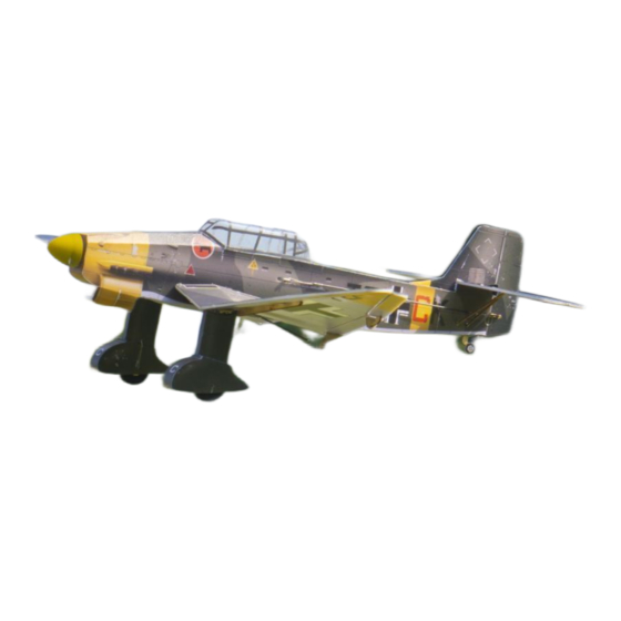
Ju-87
Assembly Instructions
Important Instructions
1.The model is supplied with UFO and 502 glue. UFO is for bonding foam parts, and 502 for bonding
wood, carbon fiber and metal parts. 502 glue will cause serious corrosion to foam parts.
2.Please wait for the glue to dry and solidify in each installation step before the next installation.
3.Please avoid using flame to heat the heat shrinkable tube on the model. Electric iron shall be used
for heating.
4.Please use razor blade to remove the parts from the plate. Do not tear the parts by force.
Advertisement

Related Manuals for MinimumRC Ju-87


Summary of Contents for MinimumRC Ju-87
- Page 1 Ju-87 Assembly Instructions Important Instructions 1.The model is supplied with UFO and 502 glue. UFO is for bonding foam parts, and 502 for bonding wood, carbon fiber and metal parts. 502 glue will cause serious corrosion to foam parts. 2.Please wait for the glue to dry and solidify in each installation step before the next installation.
- Page 2 1. Fuselage wooden frame parts. 2. Assemble the fuselage wooden frame. 3. Use glue to secure the servo spacer. (Bottom view of the parts)
- Page 3 4. Continue assembling the wooden frame and install the motor. 5. Install the servo as shown. (Top view of the parts)
- Page 4 7. Install the servo as shown. (Bottom view of the parts) 8. Magnets and its supporting structures. 9. Install the magnet.
- Page 5 10. Install the assembled magnet-supporting structure onto the wooden frame at the corresponding location. 11. Connect the receiver to the servos, secure the receiver with Velcro, power it on, and bind it to the transmitter to ensure that the servo arms return to their neutral positions. Test if the servos are functioning correctly and install the servos and arms as shown in the diagram.
- Page 6 12. Fuselage components. 13. Use a sharp tool (screwdriver) to score through the marked lines on the fuselage.
- Page 7 16. Use glue to assemble one side of the fuselage with the inner structure.
- Page 8 17. PS foam parts. 18. Use glue to attach the foam board at the top of the aircraft tail. 19. Use glue to secure the nose filler plate.
- Page 9 20. Use glue to secure the cockpit foam board. 21. Use glue to secure the front fuselage top plate. 22. Use glue to secure the foam board at the bottom of the tail of the aircraft.
- Page 10 23. Assemble the air intake baffle. 24. Use glue to secure the air intake baffle, and press it along the engraved lines against the fuselage.
- Page 11 25.Use glue to secure the fuselage bottom plate, do not apply glue to the red-lined section. 26. Combine the fuselage.
- Page 12 27.Install the bottom plate of the nose air intake. 28. Remove the propeller and apply the fuselage stickers. 29. Install magnets at the circular hole position of the battery compartment cover.
- Page 13 30. Seal the mounting holes with sticker. 32. Install the tailwheel in the corresponding slot on the bottom of the aircraft.
- Page 14 33. Apply stickers to the aircraft tailwheel. 34. Install the propeller and spinner, using a small amount of glue to secure the spinner.
- Page 15 35. Trim the excess portions of the vacuum-formed canopy as shown in the diagram. It is advisable to make a conservative initial cut, place the canopy on the fuselage for alignment, and then proceed with precise adjustments.
- Page 16 37. Trim to the finished size. 38. Glue the canopy onto the fuselage at the corresponding location. 39. Apply stickers to the canopy.
- Page 17 40. Use a sharp tool (screwdriver) to score through the marked lines on the bottom of the horizontal stabilizer, allowing the elevator to move freely along the lines on both sides. 41. Use a sharp tool (screwdriver) to score through the marked lines on the bottom of the vertical stabilizer, allowing the rudder to move freely along the lines on both sides.
- Page 18 42.Install the vertical stabilizer reinforcement. 43. Attach the vertical stabilizer to the horizontal stabilizer.
- Page 19 44.Attach the horizontal stabilizer to the corresponding location on the fuselage, ensuring that the horizontal stabilizer is parallel to the wing spar. 45. Use stickers to conceal the vertical stabilizer reinforcement.
- Page 20 46.Install the horizontal tail fin bracket.
- Page 21 48.Use a sharp tool (screwdriver) to score along the wing's marked line, allowing the wing to fold downward along the center longitudinal line to form the airfoil. 49. Use a sharp tool (screwdriver) to score along the wing's marked line, allowing the wing to fold downward along the center longitudinal line to form the airfoil.
- Page 22 50.Use a sharp tool (screwdriver) to score along the aileron's marked line, allowing the aileron to move up and down along the line. 51. Use a sharp tool (screwdriver) to score along the aileron's marked line, allowing the aileron to move up and down along the line.
- Page 23 52. Install the inner section of the wing. 53. Install the outer section of the wing.
- Page 24 54.Do not apply glue at the intersection of the aileron and wing within the red-lined. 55. The landing gear on both sides is designed to be mirror symmetric. Synchronize the mirror symmetric assembly of both landing gears to avoid confusion.
- Page 25 56. Assemble both landing gears. 57. Use the locator to determine the fixed position of the landing gear and glue it in place. (Note: The locator does not need to be fixed.)
- Page 26 58. Use the locator to install the landing gear on the other side. 59. Adjust the landing gear wires to make them perpendicular to the ground.
- Page 27 60. Axle sleeves, hubs, and tires. 61. Assemble the axle sleeve and hub, securing with glue. 62. Assemble the hub and tire, securing with glue.
- Page 28 63. Apply stickers to the hub. 64. Install the wheels and bend the landing gear wire ends upward to prevent the wheels from coming off. Alternatively, cut a small piece of heat shrink tubing, slide it onto the end of the wire, shrink it, and apply a small amount of adhesive to prevent the wheels from coming off.
- Page 29 65. One side landing gear foam components. Please pay attention to identification to avoid confusion. 66. Overlap and bond two identical PS foam boards.
- Page 30 67. As shown in the diagram, overlap and bond another PS foam board. 68. Assemble the PS foam board and printed KT board according to the corresponding outlines.
- Page 31 70. Utilize the engraved lines for assistance in positioning, install the landing gear support foam board, and pay attention to the front and rear orientation to avoid confusion.
- Page 32 72. Utilize the engraved lines for assistance in positioning, install the landing gear support foam board on the other side, and pay attention to the front and rear orientation to avoid confusion.
- Page 33 73. The assembly of the two parts of the single landing gear is complete. 74. Install the thicker landing gear foam board component on the outer side of the landing gear.
- Page 34 75. Install the thinner landing gear foam board component on the inner side of the landing gear. 76. The foam component for the other side of the landing gear. Please pay attention to identification to avoid confusion.
- Page 35 77. Overlap and bond two identical PS foam boards. 78. As shown in the diagram, overlap and bond another PS foam board.
- Page 36 79. Assemble the PS foam board and printed KT board according to the corresponding outlines.
- Page 37 81. Use the engraved lines for assistance in positioning, install the landing gear support foam board, and pay attention to the front and rear orientation to avoid confusion.
- Page 38 83. Utilize the engraved lines for assistance in positioning, install the landing gear support foam board on the other side, and pay attention to the front and rear orientation to avoid confusion. 84. The assembly of the two parts of the single landing gear is complete.
- Page 39 85. Install the thicker landing gear foam board component on the outer side of the landing gear. 86. Install the thinner landing gear foam board component on the inner side of the landing gear.
- Page 40 88. Apply landing gear stickers, and use glue to assist in securing them in place. 89. Aileron linkage parts.
- Page 41 90. Install the aileron linkage parts. 91. Install the aileron control horn. 92. Install the rudder control horn.
- Page 42 93. Install the elevator control horn. 94. Install the rudder control horn connecting hook. 95. Install the elevator control horn connecting hook.
- Page 43 96. Cut four 5mm lengths of heat shrink tubing for connecting the tail control rods and wire. 97. Use heat shrink tubing to connect the control rods and servo wire clamp heads, then apply 502 glue for fixation.
- Page 44 98.Mount the control rod clamp heads on the servo arms. 99. Trim the carbon fiber rod to the appropriate length. Use heat shrink tubing to connect the carbon fiber rod to the connection hook, then apply 502 glue for fixation.
- Page 45 100. 101. Cut a 40mm length of carbon rod for use as the aileron linkage. Use heat shrink tubing to connect the linkage to the servo wire clamp, and apply 502 glue to secure it.
- Page 46 102. Install connection hooks on the aileron control horns. 103. Insert the wire clamp heads into the fuselage and install them on the aileron servo arms.
- Page 47 104.Use heat shrink tubing to connect the aileron wire clamp heads to the connection hooks, then apply 502 glue for fixation. 105.
- Page 48 106. Place the battery in the cabin. Assembly complete!
-
Page 49: Maiden Flight
Maiden flight ·The center of gravity of the aircraft is located at the front score line of the upper wing. ·The active range of ailerons, elevator and rudder is 5mm on both sides. ·choose grass land for maiden flight. ·Under no circumstances should the landing gear in motion be obstructed, as it may result in damage to the servo gears.
Need help?
Do you have a question about the Ju-87 and is the answer not in the manual?
Questions and answers