Advertisement
Quick Links
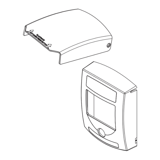
flush mount version
(2) #6-32 x 1.0 in.
Push button operating element
(OPTIONAL CAMERA)
See camera operation manual
Installation Components
Camera model surface mount version shown
FRAME MOUNTS TO:
MOUNTING HOLE KEY
SCREW SIZE REQUIRED
• Single gang box
KIT-GLR-BB-R
#10 x 3/4 in. pan-sms
• Double gang box
Four square box
#8-32 x 1.0 in. machine screw
• Four square box
Double gang box
#6-32 x 1.0 in. machine screw
• 60.3 mm European box
60.3mm European box
M3.5 x 35mm machine screw
• KIT-GLR-BB-R
Single gang box
#6-32 x 1.0 in. machine screw
RESET
1.75 in.
(44.5 mm)
Key
CR123A Lithium battery
Volume Jumper
*Mylar
Screw
Button
5.43 in.
Volume Jumper
HI
LOW
(137.8 mm)
MOUNTING HOLE KEY
HIGH
4.12 in.
KIT-GLR-BB-R
(default)
(104.8 mm)
Four square box
2.9 in.
Double gang box
2.06 in.
5.43 in.
(73mm)
60.3mm European box
(52.4 mm)
(137.8 mm)
Single gang box
HI
LOW
2.9 in.
LOW
(73mm)
*Remove Mylar for sounder activation
A
WARNING The Global Fire alarm initiating station has been tested and listed to UL38
and ULC S528. It is important to read, understand and follow all instructions provided
with this product. It is the installer's responsibility to comply with NFPA72 and 101, NEC,
mounting specifications according to ADA, CSA C22.1 Part 1 Canadian Electrical Code,
CAN/ULC-S524 Installation Fire Alarm Systems, and other applicable fire and electrical
codes. Do not paint or alter the factory finish in any manner. After installation and testing
are complete, provide a copy of this manual to all personnel responsible for testing and
maintenance of this product. Regular testing of these products, in accordance to NFPA
standards, is required. Safety Technology International is not responsible for improperly
installed, tested or maintained devices.
USA
FRAME MOUNTS TO:
• Single gang box
• Double gang box
• Four square box
• 60.3 mm European box
• KIT-GLR-BB-R
FRAME MOUNTS TO:
• Single gang box
• Double gang box
• Four square box
• 60.3 mm European box
When anchors are used drill
• KIT-GLR-BB-R
3/16 dia. holes 1-1/4 in. deep
1/2 in. NPT Thread
When anchors are not used drill
Drill (4) 11/64 in. holes
7/64 dia. 1-1/4 in. deep
4.125 in.
for general wall mount
(104.77 mm)
2.65 in.
0.61 in.
(67.3 mm)
(15.5 mm)
1.95 in.
(49.5 mm)
1.48 in.
Mounting Hardware Included
(37.6 mm)
with Flush Mount Version
2 - #6-32 x 1.0 in.
2 - M3.5 x 35mm
4.05 in.
(83.34 mm)
Key
(102.9 mm)
#8 x 1.5 in, sheet metal screw
used to mount back box to surface
(4) provided with back box option
1/2 in. NPT plug
Key
(2) provided with back box option
#10 x 3/4 in. phillips pan head screw
Drill (2) 9/64 in. holes
used to attach frame to back box
to mount to standard
(4) provided with back box option
single gang box
Mounting hardware included with
flush mount version
(2) #6-32 x 1.0 in.
Push button operating element
MOUNTING HOLE KEY
4.12 in.
KIT-GLR-BB-R
(OPTIONAL CAMERA)
(104.8 mm)
Four square box
See camera operation manual
Double gang box
2.06 in.
Pre Activation Alarm
60.3mm European box
(52.4 mm)
Single gang box
MOUNTING HOLE KEY
Button lever
4.12 in.
KIT-GLR-BB-R
Sound and LED PCB
Relay Specs
(104.8 mm)
Four square box
• Relay Terminal Rating
Double gang box
2.06 in.
Wire size:
• DC: 30VDC, 1A
60.3mm European box
(52.4 mm)
14-30 AWG
Single gang box
Strip wires:
• AC: 30VAC, 0.3A
1/4 in. (6-7mm)
Detail A
KIT-321 (Relay Wire Harness)
Not included
SCREW SIZE REQUIRED
• Yellow: NO
#10 x 3/4 in. pan-sms
Drill (4) 11/64 in. holes
• Blue: COM
for general wall mount
#8-32 x 1.0 in. machine screw
• Green: NC
#6-32 x 1.0 in. machine screw
• Red: External Power
M3.5 x 35mm machine screw
0.61 in.
• Black: Ground
#6-32 x 1.0 in. machine screw
(15.5 mm)
Detail A
1.95 in.
RESET
(49.5 mm)
ATTENTION La station d'initiation de l'alarme incendie Global Fire a été testée et répertoriée sur UL38
1.75 in.
1.48 in.
et ULC S528. Il est important de lire, comprendre et suivre toutes les instructions fournies avec ce
(44.5 mm)
(37.6 mm)
produit. Il incombe à l'installateur de se conformer aux normes NFPA72 et 101, NEC, aux spécifications
de montage selon ADA, CSA C22.1 Partie 1 Code canadien de l'électricité, CAN/ULC-S524 Installation
des systèmes d'alarme incendie, et autres codes de prévention des incendies et codes électriques
4.05 in.
NC
NO COM
applicables. Ne pas peindre ou modifier la finition d'usine de quelque manière que ce soit. Une fois
(102.9 mm)
l'installation terminée, fournir une copie de ce manuel à tout le personnel responsable des essais et de
la maintenance de ce produit. Des tests réguliers de ces produits, conformément aux normes NFPA,
sont nécessaires. Safety Technology International n'est pas responsable des dispositifs installés, testés
ou maintenus de manière incorrecte.
Drill (2) 9/64 in. holes
All specifications and information shown were current as of publication and are subject to change without notice.
to mount to standard
single gang box
When anchors are used drill
3/16 dia. holes 1-1/4 in. deep
1/2 in. NPT Thread
When anchors are not used drill
7/64 dia. 1-1/4 in. deep
When anchors are used drill
Back Box
3/16 dia. holes 1-1/4 in. deep
Red with 1/2 in. NPT thread
1/2 in. NPT Thread
top and bottom
When anchors are not used drill
Models with camera
7/64 dia. 1-1/4 in. deep
KIT-GFC-BB
Models without camera
KIT-GFA-BB
Recommended mounting height is measured from the
center of the push button to the floor level:
Mounting Hardware Included
• NFPA 72: 42 in. - 48 in.
with Flush Mount Version
2 - #6-32 x 1.0 in.
• ULC S524: 1.35 m - 1.5 m
2 - M3.5 x 35mm
• BS5839 1.2 m - 1.6 m
NOTE: verify and comply with local AHJ
Back Box
0.74 in.
#8 x 1.5 in, sheet metal screw
Red with 1/2 in. NPT thread
Mounting Hardware Included
(18.7 mm)
used to mount back box to surface
with Flush Mount Version
top and bottom
(4) provided with back box option
2 - #6-32 x 1.0 in.
Models with camera
1.08 in.
2 - M3.5 x 35mm
1/2 in. NPT plug
KIT-GFC-BB
(27.4 mm)
(2) provided with back box option
Models without camera
#10 x 3/4 in. phillips pan head screw
#8 x 1.5 in, sheet metal screw
KIT-GFA-BB
RESET
used to attach frame to back box
used to mount back box to surface
(4) provided with back box option
(4) provided with back box option
HI
LOW
Mounting hardware included with
HIGH
1/2 in. NPT plug
flush mount version
1
(default)
(2) provided with back box option
(2) #6-32 x 1.0 in.
3.281 in.
5.43 in.
#10 x 3/4 in. phillips pan head screw
Push button operating element
2
(137.8 mm)
used to attach frame to back box
(4) provided with back box option
(OPTIONAL CAMERA)
Mounting hardware included with
See camera operation manual
flush mount version
5.43 in.
(2) #6-32 x 1.0 in.
(137.8 mm)
HI
LOW
5.43 in.
Push button operating element
LOW
(137.8 mm)
(OPTIONAL CAMERA)
2.9 in.
See camera operation manual
(73mm)
2.9 in.
COM IN COM OUT
(73mm)
F
TO NEXT
A
INITIATING DEVICE
OR
C
EOL RESISTOR
SCREW SIZE REQUIRED
P
#10 x 3/4 in. pan-sms
Drill (4) 11/64 in. holes
N.O. IN N.O. OUT
for general wall mount
#8-32 x 1.0 in. machine screw
#6-32 x 1.0 in. machine screw
M3.5 x 35mm machine screw
0.61 in.
#6-32 x 1.0 in. machine screw
(15.5 mm)
SCREW SIZE REQUIRED
#10 x 3/4 in. pan-sms
Drill (4) 11/64 in. holes
Camera accessory
Camera user manual
Camera reset button
#8-32 x 1.0 in. machine screw
relay cable access
for general wall mount
#6-32 x 1.0 in. machine screw
1.95 in.
M3.5 x 35mm machine screw
0.61 in.
RESET
(49.5 mm)
(15.5 mm)
#6-32 x 1.0 in. machine screw
FRAME MOUNTS TO:
1/2 in. NPT Thread
1.75 in.
1.48 in.
• Single gang box
(44.5 mm)
(37.6 mm)
• Double gang box
• Four square box
• 60.3 mm European box
1.95 in.
4.05 in.
• KIT-GLR-BB-GY
RESET
(49.5 mm)
(102.9 mm)
1.48 in.
1.75 in.
4.125 in.
(44.5 mm)
(37.6 mm)
(104.77 mm)
2.65 in.
0.74 in.
4.05 in.
(67.3 mm)
(18.7 mm)
(102.9 mm)
1.08 in.
Drill (2) 9/64 in. holes
(27.4 mm)
to mount to standard
single gang box
Reset lever slide
Reset lever
direction marker
Drill (2) 9/64 in. holes
to mount to standard
single gang box
RESET
3.281 in.
(83.34 mm)
GF FIRE SERIES
Push button operating element
Key
(OPTIONAL CAMERA)
Detail A
See camera operation manual
Key
Key
CR123A Lithium battery
Key
Mounting Options
CR123A Lithium battery
Back Box
Red with 1/2 in. NPT thread
HI
LOW
Volume Jumper
top and bottom
Models with camera
HIGH
KIT-GFC-BB
(default)
Models without camera
Button lever
KIT-GFA-BB
CR123A Lithium battery
*Mylar
Sound and LED PCB
MOUNTING HOLE KEY
Volume Jumper
HI
LOW
Screw
4.12 in.
4.12 in.
KIT-GLR-BB-R
HIGH
(104.8 mm)
(104.8 mm)
Button
Four square box
(default)
HI
LOW
Double gang box
2.06 in.
2.06 in.
LOW
60.3mm European box
(52.4 mm)
(52.4 mm)
Single gang box
Volume Jumper
HI
LOW
LOW
3
4
*Remove Mylar for sounder activation
Back Box Installation prep.
4.125 in.
(104.77 mm)
2.65 in.
0.74 in.
(67.3 mm)
(18.7 mm)
4.125 in.
1.08 in.
(104.77 mm)
(27.4 mm)
2.65 in.
When anchors are used drill
0.74 in.
(67.3 mm)
3/16 dia. holes 1-1/4 in. deep
(18.7 mm)
When anchors are not used drill
1.08 in.
7/64 dia. 1-1/4 in. deep
(27.4 mm)
3.281 in.
5.43 in.
(83.34 mm)
(137.8 mm)
Back Box
Red with 1/2 in. NPT thread
top and bottom
Models with camera
KIT-GFC-BB
3.281 in.
5.43 in.
Models without camera
(83.34 mm)
(137.8 mm)
KIT-GFA-BB
RESET
1
#8 x 1.5 in, sheet metal screw
WARNING: This product can expose you to chemicals including Dichloromethane, which
used to mount back box to surface
5.43 in.
is known to the State of California to cause cancer, and Bisphenol A (BPA), which is
(4) provided with back box option
2
(137.8 mm)
known to the State of California to cause birth defects or other reproductive harm. For
1/2 in. NPT plug
more information go to www.P65Warnings.ca.gov.
(2) provided with back box option
#10 x 3/4 in. phillips pan head screw
Three year warranty or a one year limited warranty (from date of purchase) on most
used to attach frame to back box
products. See website for details. Electronic warranty form at www.sti-usa.com/wc14.
Camera reset button
(4) provided with back box option
Mounting hardware included with
SIDE 1
Wire size:
flush mount version
14-30 AWG
(2) #6-32 x 1.0 in.
Strip wires:
1/4 in. (6-7mm)
Camera reset button
GFIS OCT2024
Wire size:
14-30 AWG
Strip wires:
#10 x 3/4 in. phillips pan head screw
Mounting hardware included with
used to mount back box to surface
used to attach frame to back box
(4) provided with back box option
flush mount version
(4) provided with back box option
(2) #6-32 x 1.0 in.
1/2 in. NPT plug
Mounting hardware included with
(2) provided with back box option
Push button operating element
flush mount version
#10 x 3/4 in. phillips pan head screw
(2) #6-32 x 1.0 in.
used to attach frame to back box
(OPTIONAL CAMERA)
Push button operating element
(4) provided with back box option
See camera operation manual
Mounting hardware included with
Button lever
(OPTIONAL CAMERA)
flush mount version
*Mylar
(2) #6-32 x 1.0 in.
Sound and LED PCB
See camera operation manual
Screw
COM IN COM OUT
Push button operating element
(OPTIONAL CAMERA)
Button
F
TO NEXT
See camera operation manual
A
INITIATING DEVICE
Button lever
C
EOL RESISTOR
*Mylar
Frame mounting options recommended
Sound and LED PCB
P
Screw
mounting height above finished floors:
N.O. IN N.O. OUT
Button
Not less than 3.5 ft. (1.1 m.)
Greater than 4.5 ft. (1.37 m.)
Flush mount options
MOUNTING HOLE KEY
SCREW SIZE REQUIRED
SCREW SIZE REQUIRED
MOUNTING HOLE KEY
SCREW SIZE REQUIRED
KIT-GLR-BB-R
#10 x 3/4 in. pan-sms
#10 x 3/4 in. pan-sms
Drill (4) 11/64 in. holes
KIT-GLR-BB-GY
#10 x 3/4 in. pan-sms
#8-32 x 1.0 in. machine screw
for general wall mount
Four square box
#8-32 x 1.0 in. machine screw
Four square box
#8-32 x 1.0 in. machine screw
#6-32 x 1.0 in. machine screw
#6-32 x 1.0 in. machine screw
Double gang box
FRAME MOUNTS TO:
Double gang box
#6-32 x 1.0 in. machine screw
M3.5 x 35mm machine screw
0.61 in.
60.3mm European box
• Single gang box
60.3mm European box
M3.5 x 35mm machine screw
M3.5 x 35mm machine screw
*Remove Mylar for sounder activation
(15.5 mm)
#6-32 x 1.0 in. machine screw
• Double gang box
Single gang box
Single gang box
#6-32 x 1.0 in. machine screw
#6-32 x 1.0 in. machine screw
• Four square box
• 60.3 mm European box
• KIT-GLR-BB-GY
1.95 in.
RESET
*Remove Mylar for sounder activation
(49.5 mm)
RESET
1.48 in.
1.75 in.
(44.5 mm)
(37.6 mm)
1.75 in.
(44.5 mm)
4.05 in.
(102.9 mm)
Drill (2) 9/64 in. holes
to mount to standard
single gang box
European Electrical Box
1. Remove four (4) screws to access moutning positions.
2. Mount the plate to an electrical box using
two (2) M3.5 screws.
3. Place mechanism assembly on to the frame.
Key
4. Insert four (4) screws.
RESET
1
3
2
4
RESET
Detail A
1
3
4
2
Detail A
3
A
4
Camera accessory
Camera user manual
relay cable access
A
ADA
Camera accessory
Camera user manual
relay cable access
Compliant
OR
Drill (4) 11
for genera
(1
1
(4
4.05 in.
(102.9 mm
MO
6
NC
Advertisement

Related Manuals for STI GF FIRE Series


Summary of Contents for STI GF FIRE Series
- Page 1 Safety Technology International is not responsible for improperly sont nécessaires. Safety Technology International n’est pas responsable des dispositifs installés, testés used to attach frame to back box products. See website for details. Electronic warranty form at www.sti-usa.com/wc14. Camera accessory ou maintenus de manière incorrecte.
- Page 2 #8-32 x 1.0 in. machine screw (104.77 mm) SIDE 2 #6-32 x 1.0 in. machine screw ble gang box 2.65 in. 0.74 in. GF FIRE SERIES m European box M3.5 x 35mm machine screw 0.61 in. MOUNTING (67.3 mm) (18.7 mm)
Need help?
Do you have a question about the GF FIRE Series and is the answer not in the manual?
Questions and answers