Advertisement
Advertisement
Table of Contents

Related Manuals for Patriot Lighting 25008


Summary of Contents for Patriot Lighting 25008
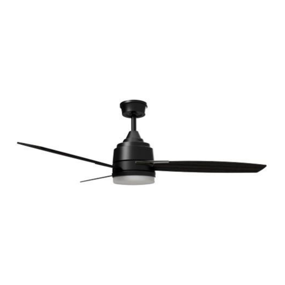
- Page 1 52” Voyager Indoor Ceiling Fan Owner’s Manual Model #25008 SKU # 355-1604...
-
Page 2: Safety Instructions
SAFETY INSTRUCTIONS WARNING: • To avoid risk of electrical shock, be sure to shut off power at the main fuse or circuit breaker panel box before installing or servicing this fixture. Turning off the electrical power by using the light switch only is not sufficient to prevent electrical shock hazard. •... -
Page 3: Package Contents
PACKAGE CONTENTS PART DESCRIPTION QUANTITY PART DESCRIPTION QUANTITY Mounting Bracket and (2) canopy screws Blade Screws and Washers 9 each Downrod and Downrod Ball Light Kit Plate Light Kit Screws (pre-installed Downrod Pin (pre-installed) on motor shaft ring) LED Lighting Board and (Screws Downrod Clip (pre-installed) pre-installed on light kit plate) Canopy... -
Page 4: Hardware Kit Contents
HARDWARE KIT CONTENTS NOTE: For your convenience some extra hardware may be included. The quantity listed above is the number required for installation. TOOLS REQUIRED (not included) Tools required for assembly: Step Ladder, Phillips Screwdriver, Wire Strippers, Safety Glasses, Pliers, and Electrical Tape. Helpful Tools: AC Tester Light/Multimeter, Tape Measure, and Wiring Handbook. - Page 5 DIMENSION REFERENCE A: 16.5 in. B: 14.1 in. C: 8.5 in. D: 5.7 in. (Note: Dimensions with 6” downrod) Choose one of the following mounting options: Downrod Mount is best suited for ceilings 8 ft. or higher. For taller ceilings you may want to use a longer downrod (sold separately).
- Page 6 ASSEMBLY INSTRUCTIONS Turn OFF the electrical power at the main fuse or circuit breakers. NOTE: Before continuing installation, confirm that the power is still turned off at the main circuit breaker or by removing the correct fuse. Turning the power off using a wall switch is not sufficient to prevent electrical shock.
- Page 7 ASSEMBLY INSTRUCTIONS 4. Loosen but do not remove the two set screws in the yoke. Set screws need to be loosened enough to fully insert the downrod. 5. Feed the entire length of the 3 wires coming from the fan through the bottom of the downrod and out the top of the downrod ball.
- Page 8 ASSEMBLY INSTRUCTIONS 6. Lift the downrod into the mounting bracket. Rotate the downrod until the tab in the mounting bracket is seated in the slot in the downrod ball. WARNING: The fan and/or downrod Slot should not rotate in the mounting bracket if installed correctly.
- Page 9 ASSEMBLY INSTRUCTIONS Use the supplied wire connectors to connect the fan wires to the remote receiver and then the receiver to the power supply wires according to the wiring diagram and following instructions: Connecting the fan to the remote receiver: •...
-
Page 10: Installing The Blades
ASSEMBLY INSTRUCTIONS 9. Locate the (2) previously loosened screws on underside of hanging bracket. Place rounded part of slotted hole in canopy over the loosened screws in hanging bracket and push up. Make sure all wires are tucked into the canopy and will not be pinched, including the black antenna wire. -
Page 11: Installing The Light Kit
ASSEMBLY INSTRUCTIONS INSTALLING THE LIGHT KIT 12. Remove one (1) of the pre-installed screws on the motor shaft ring and loosen the other two (2) screws. Position the light kit plate under the fan and feed the light kit wire through the cut out in the center of the light kit plate. - Page 12 ASSEMBLY INSTRUCTIONS 14. INSTALLING THE LIGHT KIT GLASS Position the glass bowl to line up with the bottom of the light kit. While holding the glass up to the bottom of the light kit, turn the glass clockwise until the notch in the glass slips into the light kit channel.
- Page 13 OPERATING INSTRUCTIONS USING THE REMOTE CONTROL Power • Power button: Turns fan ON/OFF. The remote has built-in memory: the fan and light will come on at the same settings as the last time Fan Speed the power supply was turned off. Timer •...
- Page 14 OPERATING INSTRUCTIONS OPTIMIZING YOUR FAN’S PERFORMANCE Reverse USING THE REVERSE SWITCH Switch Use the fan reverse switch, located on the top of the motor housing underneath the yoke cover, to optimize your fan for seasonal performance. Using a ceiling fan will allow you to raise your thermostat setting in summer and lower your thermostat setting in winter without...
-
Page 15: Troubleshooting
TROUBLESHOOTING FAN DOES NOT START: • Check the circuit breaker and confirm the power is ON. • Make sure the wall switch is ON. • Confirm the battery is installed correctly in the handheld remote; install fresh batteries. • Make sure you are in the normal range for the remote control of 10’ – 20’ (3m – 6m). •... -
Page 16: Limited Lifetime Warranty
If your Patriot Lighting Ceiling Fan motor fails at any time during the lifetime of the original purchaser due to defects in material or workmanship, we will provide a replacement part free of charge.
Need help?
Do you have a question about the 25008 and is the answer not in the manual?
Questions and answers
How do I turn the light on without the **** coming on every time
To turn on the Patriot Lighting 25008 ceiling fan without activating the "Safe Exit" feature, simply press the light or fan power button briefly. Avoid holding the fan OFF button for 5 seconds, as this will initiate the Safe Exit mode.
This answer is automatically generated