Rockwell Automation Allen-Bradley Guardmaster MSR55P User Manual
Back emf minotaur safety relay
Hide thumbs
Also See for Allen-Bradley Guardmaster MSR55P:
- Installation instructions (4 pages) ,
- User manual (50 pages)

Related Manuals for Rockwell Automation Allen-Bradley Guardmaster MSR55P


Summary of Contents for Rockwell Automation Allen-Bradley Guardmaster MSR55P
- Page 1 MSR55P Back EMF Minotaur Safety Relay Catalog Numbers 440R-S35011, 440R-S35012, 440R-S35013, 440R-S35014, 440R-S35015, 440R-S35016 User Manual Original Instructions...
-
Page 2: Important User Information
If this equipment is used in a manner not specified by the manufacturer, the protection provided by the equipment may be impaired. In no event will Rockwell Automation, Inc. be responsible or liable for indirect or consequential damages resulting from the use or application of this equipment. -
Page 3: Table Of Contents
Potentiometer Error..........27 Rockwell Automation Publication 440R-UM014I-EN-P - December 2022... - Page 4 ............47 Rockwell Automation Publication 440R-UM014I-EN-P - December 2022...
-
Page 5: Who Should Use This Manual
The exception is the semiconductor output ERR, which is not described in De-energized Table 1 on page 6. The ERR semiconductor output is ON when an error is detected and OFF when no error is detected. Rockwell Automation Publication 440R-UM014I-EN-P - December 2022... -
Page 6: Additional Resources
Industrial Automation Wiring and Grounding Guidelines, publication 1770-4.1 Provides general guidelines for installing a Rockwell Automation industrial system. Product Certifications website, rok.auto/certifications. Provides declarations of conformity, certificates, and other certification details. You can view or download publications at rok.auto/literature. -
Page 7: Safety Relay Features
To accommodate many types of motors, you can make two adjustments in accordance with the machine risk assessment: • The threshold of the back EMF voltage. • A time delay to add additional assurance that the motor has stopped. Rockwell Automation Publication 440R-UM014I-EN-P - December 2022... - Page 8 20…400 mV 440R-S35011 115V AC 20…400 mV Induction motors 440R-S35012 230V AC 20…400 mV 440R-S35013 24V DC 200 mV…4V 440R-S35014 Servo (permanent 115V AC 200 mV…4V 440R-S35015 magnet) motors 230V AC 200 mV…4V 440R-S35016 Rockwell Automation Publication 440R-UM014I-EN-P - December 2022...
-
Page 9: Installation
2. Slide down until the housing catches the rail. 3. Swing the bottom down and push until the latch clips onto the rail. Figure 3 - DIN Rail Mounting DIN Rail Latch DIN Rail Rockwell Automation Publication 440R-UM014I-EN-P - December 2022... -
Page 10: Removal
1. Insert the tip of a small screwdriver into the slot near the terminal screws. 2. To unlock the terminal block, rotate the screwdriver. The terminal block can then be removed from the housing. Rockwell Automation Publication 440R-UM014I-EN-P - December 2022... -
Page 11: Enclosure Considerations
Harmful contaminants or dirt could damage components or cause improper operation. In extreme cases, you need air conditioning to help protect against heat buildup within the enclosure. Rockwell Automation Publication 440R-UM014I-EN-P - December 2022... - Page 12 Chapter 2 Installation Notes: Rockwell Automation Publication 440R-UM014I-EN-P - December 2022...
-
Page 13: Power, Ground, And Wire
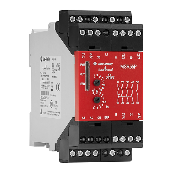
Figure 5 on page 14 shows the front face marking of each of the safety relays, including the terminal and status indicator identifications. The difference between the two models is the standstill monitoring voltage, V Rockwell Automation Publication 440R-UM014I-EN-P - December 2022... -
Page 14: Connect Power Supply
A3/A4 to provide semiconductor diagnostics. Depending on the model, the primary supply can be 24V DC, 115V AC or 230V AC. When an AC supply is used, both 50 Hz and 60 Hz are acceptable. Rockwell Automation Publication 440R-UM014I-EN-P - December 2022... -
Page 15: Motor Winding Inputs
Figure 8 on page 16 shows wiring for a 3-phase motor. IMPORTANT The three connections create two safety monitoring channels. L1 is the common to the two channels, which are L2 and L3. Rockwell Automation Publication 440R-UM014I-EN-P - December 2022... -
Page 16: Safety Outputs
Calculate the total quadratic current, which is the sum of the squares of the currents through each of the safety outputs. Rockwell Automation Publication 440R-UM014I-EN-P - December 2022... -
Page 17: Surge Suppressors
MSR55P safety relay contacts. Figure 11 on page 18 shows examples of output contactors with a suppression device. We recommend that you locate the suppression device as close as possible to the load device. Rockwell Automation Publication 440R-UM014I-EN-P - December 2022... -
Page 18: Auxiliary Outputs
The ERR output turns on when an error is detected by the MSR55P safety relay. The semiconductor outputs require a separate 24V DC connection and must have a common reference to the PLC. Rockwell Automation Publication 440R-UM014I-EN-P - December 2022... -
Page 19: Monitoring Input
The MSR55P safety relay is shipped from the factory with a jumper from X1 to ATTENTION: Terminals X1-X2-X3 have electrical connections to measuring inputs L1-L2-L3. Voltage-free contacts that are rated for L1-L2-L3 voltage must be used for these connections. Rockwell Automation Publication 440R-UM014I-EN-P - December 2022... -
Page 20: Fault Reset Input
Figure 14 - Fault Reset Circuit Examples 43 53 X1 X2 43 53 X1 X2 34 44 ON ERR A4 34 44 ON ERR A4 Automatic Fault Reset Manual Fault Reset Rockwell Automation Publication 440R-UM014I-EN-P - December 2022... -
Page 21: Vm - Monitoring Voltage
Table 4 shows the settings of each of the catalog numbers. Table 4 - V - Monitoring Voltage Settings 440R-S35014, 440R-S35015, 440R-S35016 440R-S35011, 440R-S35012, 440R-S35013 Position [Volts] [x10mV] Rockwell Automation Publication 440R-UM014I-EN-P - December 2022... -
Page 22: Ts - Time Delay
During the timing cycle, the OUT indicator flashes. Table 5 shows the delay time for each setting. After the delay expires, the outputs are energized. Table 5 - Delay Time Settings Position Delay Time [seconds] Rockwell Automation Publication 440R-UM014I-EN-P - December 2022... -
Page 23: Timing Diagram Procedure
IMPORTANT The MSR55P safety relay does not detect line breakage with the motor running and connected to an electronic drive. 12. The line break is reinstated. 13. Upon closure of the reset signal, the outputs are energized. Rockwell Automation Publication 440R-UM014I-EN-P - December 2022... - Page 24 Figure 15 - Typical Timing Diagram 10 11 12 13 A1/A2 Motor Speed/ Voltage Voltage Level (V L1/L2/L3 Line Breakage line breakage L1/L2/L3 23-24 33-34 43-44 53-54 11-12 Standstill Delay Time t =2...2.5 s Startup Delay Time Rockwell Automation Publication 440R-UM014I-EN-P - December 2022...
- Page 25 When multiple faults exist simultaneously, the ERR indicator shows the highest priority. After the highest priority fault is corrected, the ERR shows the next highest priority fault. Figure 16 on page 26 shows the codes in order of priority. Rockwell Automation Publication 440R-UM014I-EN-P - December 2022...
-
Page 26: Err Flashing Codes
- The outputs of the MSR55P safety relay remain de-energized. - The ERR output turns ON. - The ERR status indicator flashes the code that is associated with the breakage. Rockwell Automation Publication 440R-UM014I-EN-P - December 2022... -
Page 27: Simultaneity Of Measuring Signals
If another setting is detected on the two corresponding potentiometers, the potentiometer error or t is displayed. To correct the fault, readjust the potentiometer. Be sure to feel the detent. Rockwell Automation Publication 440R-UM014I-EN-P - December 2022... -
Page 28: Internal Device Failure
Failure on safety relays (for example, welded output contacts). • Internal failures on measuring channels and measuring circuits. • Internal failures on control circuits for the safety relays. Cycle power to terminal A1 to clear the fault. Rockwell Automation Publication 440R-UM014I-EN-P - December 2022... -
Page 29: Application And Wiring Examples
440G-LZ switch, but the wiring is different. See Figure 20 on page 34 for a 5-pin wiring example. Shielded cable must be used for the motor-monitoring wires L1, L2, and L3. The shield must be grounded. Rockwell Automation Publication 440R-UM014I-EN-P - December 2022... - Page 30 34 44 ON ERR A4 Brown Gate control Gray circuit Pink Yellow Blue Green White F2 F3 Lock/Unlock 800FM- SM22MX10 ON Status Shielded Cable Gate ON Status Unlocked Error Status 800FM-P4MN3R 24V DC Com Rockwell Automation Publication 440R-UM014I-EN-P - December 2022...
-
Page 31: E-Stop With Contactors
2 3 4 5 MSR55P RESET 440R-S35011 x10mV .2 .3 .5 .7 440R-S12R2 34 44 ON ERR A4 F1 F2 Safety Devices K1 K2 ON Status 100S Contactors ON Status Error Status 24V DC Com Rockwell Automation Publication 440R-UM014I-EN-P - December 2022... -
Page 32: Wye-Delta Connections
• With 3-phase connection of the MSR55P safety relay, the wye contactor (K2) must be closed after the motor is switched off to detect standstill. If not, the failure signal (broken wire) blocks the output contacts in the off position. Rockwell Automation Publication 440R-UM014I-EN-P - December 2022... -
Page 33: Smart Motor Controller (Smc) Soft Starter
DIS safety relays, 100S contactor, and the monitoring of both the contactor Safety rating and the SMC soft starter. For guidance on safety system analysis with frequency drives, https://www.dguv.de/medien/ifa/en/pub/rep/pdf/reports2013/ifar0713e/ rep0713engl.pdf IFA Report 7/2013e, Safe drive controls with frequency converters. Rockwell Automation Publication 440R-UM014I-EN-P - December 2022... - Page 34 14 98 12 24 Brown Black Blue White F2 F3 Gray Lock/ Unlock ON Status 800FM- SM22MX10 100S- Motor ON Status Aux#1 C09EJ14BC Error Status Normal or OVLD At Speed Fault 24V DC Com Rockwell Automation Publication 440R-UM014I-EN-P - December 2022...
-
Page 35: Troubleshooting
Medium-sized screwdriver: For terminal screws, to remove terminal blocks, and to configure the switches on the front face of the safety relays. 0.5 mm (0.02 in.) 3 mm (0.12 in.) • Digital multimeter: To measure signal levels and contact resistance. Rockwell Automation Publication 440R-UM014I-EN-P - December 2022... -
Page 36: Follow These Steps
(page contactors off? (page flashes 2x or 3x? Go to Step 4 ERR indicator Output on while Go to Step 8 (page flashes 4x? motor still on? (page Safety relay is functioning properly Rockwell Automation Publication 440R-UM014I-EN-P - December 2022... -
Page 37: Step 1 - View Pwr Indicator
1X. An undervoltage exists at A1/A2. Measure the voltage at the terminal A1 to A2 as shown in Figure 22. With your schematics, trace the voltage back to its source to determine what could be the cause of the undervoltage. Rockwell Automation Publication 440R-UM014I-EN-P - December 2022... -
Page 38: Step 3 - Wire Break At L1, L2, Or L3
If the circuit is closed (measures 0 Ω), try cycling the power to the MSR55P safety relay. If the ERR continues to show four flashes, then replace the MSR55P safety relay. Rockwell Automation Publication 440R-UM014I-EN-P - December 2022... -
Page 39: Step 5 - Err Indicator Flashes 5 Times
X3/X2 connection; the reset occurs automatically. Figure 25 - Simultaneous Error 43 53 X1 X2 L1 L2 L3 34 44 ON ERR A4 Ch1=Ch2 Ohms First, remove power to L1, L2, and L3 Rockwell Automation Publication 440R-UM014I-EN-P - December 2022... -
Page 40: Step 6 - Err Flashes 6 Or 7 Times
L2/L3 to L1) or the motor generates only a low voltage. Check connection of measuring inputs to motor winding according to the connection examples. Increase the delay time t setting to allow the motor more time to spin to a stop. Rockwell Automation Publication 440R-UM014I-EN-P - December 2022... -
Page 41: Specifications
11/12,23/24,33/34,43/44 against all others 11/12,23/24,33/34,43/44 against each other 53/54 against all others IEC/EN 60664-1 A3/ON/ERR/A4 against all others A1/A2 AC against all others A1/A2 DC against all others X1/X2/X3 to L1/L2/L3 No galvanic separation Rockwell Automation Publication 440R-UM014I-EN-P - December 2022... -
Page 42: Power Supply (A1/A2)
Table 16 - Status Output Specifications Attribute Value A3/A4 power supply voltage range [V DC] 12…30 PELV/SELV or Class 2 Power consumption [W] On, ERR max current at 24V DC [mA] 53/54 contact rating [A/VAC] 3/250 Rockwell Automation Publication 440R-UM014I-EN-P - December 2022... -
Page 43: Regulatory Approval
Safety of machinery — Safety-related parts of control systems — Part 1: General principles for design This product is intended for use in an industrial environment. For a comprehensive CE certificate visit: rok.auto/certifications. Rockwell Automation Publication 440R-UM014I-EN-P - December 2022... -
Page 44: Ukca Conformity
Specifications are applicable only if the safety function is demanded at least once within 6 months. All diagnostic tests are conducted at least before next demand. At mission time (TM), the proof test interval (PTI) is assumed. Components failure rates are according to SN29500. Rockwell Automation Publication 440R-UM014I-EN-P - December 2022... -
Page 45: Sil Rating
ISO 13849-1. Table 18 - Performance Level/Category Attribute Rating Category Performance Level MTTF [years] Diagnostic Coverage, DC 99.0 Days, d [days/year] Hours, h [hours/day] [s/cycle] 28.8E cycle T [years] Rockwell Automation Publication 440R-UM014I-EN-P - December 2022... - Page 46 Appendix B Regulatory Approval Notes: Rockwell Automation Publication 440R-UM014I-EN-P - December 2022...
-
Page 47: Index
5 times 39 motor flashes 6 or 7 times 40 spinningline breakage 26 error standstill potentiometer 27 line breakage 26 E-stop motor winding with contactors 31 input 15 with electronic drive 29 Rockwell Automation Publication 440R-UM014I-EN-P - December 2022... - Page 48 L1, L2, or L3 38 output 16 wiring safety output recommendation 13 specification 42 requirements 13 SIL rating 45 wiring example 29 simultaneity wye-delta measuring signal 27 connection 32 size wire 41 spacing 10 Rockwell Automation Publication 440R-UM014I-EN-P - December 2022...
- Page 49 MSR55P Back EMF Minotaur Safety Relay User Manual Rockwell Automation Publication 440R-UM014I-EN-P - December 2022...
-
Page 50: Rockwell Automation Support
At the end of life, this equipment should be collected separately from any unsorted municipal waste. Rockwell Automation maintains current product environmental compliance information on its website at rok.auto/pec. Allen-Bradley, expanding human possibility, Guardmaster, Minotaur, PowerFlex, Rockwell Automation, and SMC are trademarks of Rockwell Automation, Inc. EtherNet/IP is a trademark of ODVA, Inc.
Need help?
Do you have a question about the Allen-Bradley Guardmaster MSR55P and is the answer not in the manual?
Questions and answers