Table of Contents
Advertisement
Quick Links
Advertisement
Table of Contents

Related Manuals for Seikom Electronic RLSW4 Series


Summary of Contents for Seikom Electronic RLSW4 Series
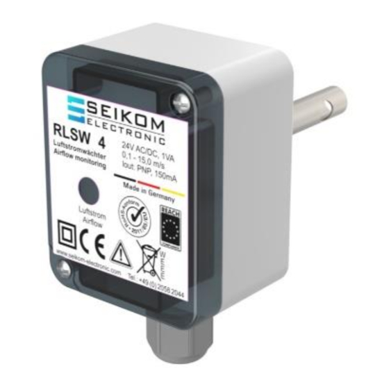
- Page 1 User Manual RLSW®4 (R) 24 V AC/DC Version 1...
- Page 2 +49 2058 916 900 0 • info@seikom-electronic.com • www.seikom-electronic.com Page: 2...
-
Page 3: Table Of Contents
User Manual RLSW®4 (R) CONTENTS CONTENTS ..........................3 1. SAFETY INSTRUCTIONS ....................4 2. GENERAL INFORMATION ....................4 2.1 Proper Use ..........................4 2.2 Function Principle ........................4 3. TECHNICAL DATA ......................5 3.1 Dimensions ..........................6 4. INSTALLATION AND COMMISSIONING ................6 4.1 Installation Conditions ...................... -
Page 4: Safety Instructions
User Manual RLSW®4 (R) 1. SAFETY INSTRUCTIONS Read the product description before commissioning the device. Make sure that the product is suitable for your application without any restrictions. Improper use or use not in accordance with the intended use can lead to malfunctions of the device or to undesirable effects your application. -
Page 5: Technical Data
User Manual RLSW®4 (R) 3. TECHNICAL DATA Type RLSW®4R Article-No. 74825R Operating voltage 24 V AC/DC Voltage tolerance ± 5% Signal lamp voltage Power consumption 1 VA Ambient temperature -20 … 60°C Switching output 1 NO-contact Switching function at flow Relay engages Relay output 250 V AC, 5 A, 1.2 kVA... -
Page 6: Dimensions
User Manual RLSW®4 (R) 3.1 Dimensions 60mm 35mm 50mm 35mm 15mm 10mm 14,2mm (10mm) M16x1,5 Locking screw 37.0 mm 4. INSTALLATION AND COMMISSIONING Installation and commissioning must be performed by authorized and qualified personnel. Connections to main supply (L, N) must be made by means of a protected isolating switch with usual fuses. -
Page 7: Installation Conditions
User Manual RLSW®4 (R) 4.1 Installation Conditions To avoid malfunctions, please refer to the following points: ▪ The tip of the sensor should be as close as possible to the centre of the pipe. The traverse hole in the shaft of the sensor must be within the full of the gaseous medium. ▪... -
Page 8: Commissioning Instructions
User Manual RLSW®4 (R) 4.4 Commissioning Instructions When commissioning and adjusting the device, the following procedure is recommended: ▪ Install and connect the flow controller in accordance with installation instructions and conditions, inlet (5 x pipe diameter) + outflow zone (3 x pipe diameter). Align the mark to the airflow. - Page 9 User Manual RLSW®4 (R) Flow is outside of the Adjust the tube’s diameter to measurement range increase or decrease the flow Device detects air flow when Air flow is present even at Adjust the sensor’s switching no air flow is present standstill e.g., due to point ventilation flaps through...
-
Page 10: Eu Declaration Of Conformity
User Manual RLSW®4 (R) 7. EU DECLARATION OF CONFORMITY +49 2058 916 900 0 • info@seikom-electronic.com • www.seikom-electronic.com Page: 10... - Page 12 Growing network of local distributors available online www.seikom-electronic.com Our Product Portfolio Flow Temperature Pressure Air Quality and CO Zener Barriers Universal Transmitters +49 2058 916 900 0 info@seikom-electronic.com www.seikom-electronic.com SEIKOM-Electronic GmbH & Co. KG Gold-Zack-Straße 7 40822 Mettmann...
Need help?
Do you have a question about the RLSW4 Series and is the answer not in the manual?
Questions and answers