Table of Contents
Advertisement
Quick Links
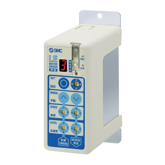
Programless Controller
Applicable to 14 points of positioning
No programming
Capable of setting up an electric actuator operation without using a PC or teaching box
Setting position number
1
Setting a registered number for
the stop position
Maximum 14 points
Position
number
display
Speed/acceleration 16-level adjustment
Speed adjustment
switches
Acceleration adjustment
switches
Compatible with actuators
with locks
Setting 3-level pushing force
Compatible electric actuator
LECP1
Series
Setting a stop position
2
Moving the actuator to a stop
position using FORWARD and
REVERSE buttons
Position
selecting
switch
INFORMATION
3
SET button
FORWARD and
REVERSE buttons
Compatible actuators
Electric Grippers
LEH
Series
Electric Slide Table
LES
Series
Electric Actuator/
Rod Type
LEY
Series
Electric Actuator/
Slider Type
LEF
Series
Electric Actuator/
r/
Guide Rod Slider
r
LEL
Series
Electric Actuator/
Low Profile Slider Type
ype
LEM
Series
Electric Actuator/
Miniature Rod Type
LEP
Series
Electric Rotary Table
able
LER
Series
Registration
Registering the stop
position using SET
button
Catalogue No.
EUS100-77
EUS100-78
EUS100-83
EUS100-87
EUS100-101
EUS100-98
EUS100-92
EUS100-94
09-EU564-Aa-UK
Advertisement
Table of Contents

Related Manuals for SMC Networks LECP1 Series


Summary of Contents for SMC Networks LECP1 Series
- Page 1 INFORMATION Programless Controller Applicable to 14 points of positioning No programming Capable of setting up an electric actuator operation without using a PC or teaching box Setting position number Setting a stop position Registration Setting a registered number for Moving the actuator to a stop Registering the stop the stop position position using FORWARD and...
-
Page 2: Specifications
LECP1 Series How to Order LEFS16B-100-R3 Controller with actuator I/O cable length [m] Actuator type — Without cable Controller type Refer to “How to Order” in the actuator catalogue and indicate the model. — Without controller For compatible actuators, refer to the table below. Example: LEFS16B-100-R31N1 With programless controller (NPN) With programless controller (PNP) -
Page 3: Controller Details
LECP1 Series Programless Controller Controller Details Display Description Details Power supply ON/Servo ON : Green turns on Power supply LED Power supply ON/Servo OFF: Green fl ashes With alarm : Red turns on Alarm LED Parameter setting : Red fl ashes Change and protection of the mode switch —... - Page 4 LECP1 Series Dimensions DIN rail mounting (LEC 1 D- ) (11.5) 36.2 DIN rail AXT100-DR- ∗ For , enter a number from the “No.” line in the table below. Refer to the dimensions above for the mounting dimensions. 12.5 5.25 (Pitch) 1.25 L Dimension [mm]...
-
Page 5: Wiring Example
LECP1 Series Programless Controller Wiring Example 1 ∗ When you connect a CN1 power supply connector, use the power supply cable (LEC-CK1-1). Power Supply Connector: CN1 ∗ Power supply cable (LEC-CK1-1) is an accessory. Power supply cable for LECP1 (LEC-CK1-1) CN1 Power Supply Connector Terminal for LECP1 Terminal name Cable colour Function... -
Page 6: Signal Timing
LECP1 Series Signal Timing (1) Return to Origin 24 V Power supply IN0-3 all ON Input IN0-3 BUSY OUT0-3 Output ALARM Release External lock Hold Speed 0 mm/s ON after controller system initialization Return to origin Output signals for OUT0, OUT1, OUT2, OUT3 are ON when return to origin is completed. - Page 7 LECP1 Series Programless Controller Options: Actuator Cable [Robotic cable, standard cable for step motor (Servo/24 VDC)] Controller side LE-CP- /Cable length: 1.5 m, 3 m, 5 m LE CP Connector C (14.2) (Terminal no.) Actuator side (Terminal no.) (13.5) Cable length (L) [m] Connector A (14.7) Connector D...
- Page 8 LECP1 Series Options [Power supply cable] LEC CK1 1 (13.3) (35) (60) (10.5) (1500) ∗ Conductor size: AWG20 Terminal name Covered colour Function Blue Common supply (−) M 24V White Motor power supply (+) C 24V Brown Control power supply (+) BK RLS Black Lock release (+)
- Page 9 With Input Signals to Perform Jog Operations, Step Motor controller LECP1-XB182 Jog operation can be performed using parallel input signals. Jog operations that could previously only be performed using the button on the front face can now be performed using the ON/OFF status of the input signal.
-
Page 10: Wiring Diagram
LECP1-XB182 How to Order LE P 1 XB182 Electric actuator With input signals to perform jog operations (Stop points: 2 points) Controller Actuator part number Compatible motor (Enter the portion from the actuator model “LE” to the “stroke”.) Example: Enter “LEHZ10LK2-4” for the LEHZ10LK2-4AF-R11N1D. Step motor (Servo/24 VDC) Parallel input/output type DIN rail... -
Page 11: Screw Mounting
With Input Signals to Perform Jog Operations LECP1-XB182 Step Motor Controller Dimensions LEC 1 -XB182 Screw mounting ( CN4 I/O connector CN3 encoder connector CN2 motor connector CN1 power supply connector 36.2 Ø 4.5 18.1 For body mounting For body mounting LEC 1 -XB182 DIN rail mounting (... - Page 12 SMC Corporation (Europe) +43 (0)2262622800 www.smc.at offi ce@smc.at +370 5 2308118 www.smclt.lt info@smclt.lt Austria Lithuania +32 (0)33551464 www.smc.be info@smc.be Netherlands +31 (0)205318888 www.smc.nl info@smc.nl Belgium +359 (0)2807670 www.smc.bg offi ce@smc.bg +47 67129020 www.smc-norge.no post@smc-norge.no Bulgaria Norway +385 (0)13707288 www.smc.hr offi ce@smc.hr +48 222119600 www.smc.pl offi...
Need help?
Do you have a question about the LECP1 Series and is the answer not in the manual?
Questions and answers