Table of Contents
Advertisement
Quick Links
Advertisement
Table of Contents

Related Manuals for SMC Networks LEFSW Series


Summary of Contents for SMC Networks LEFSW Series
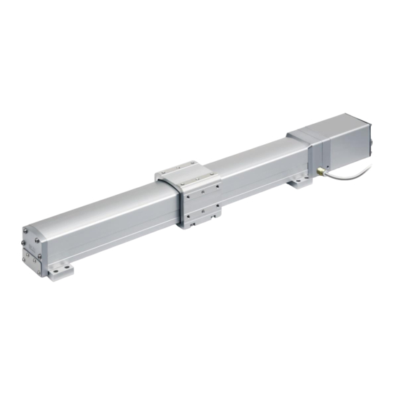
- Page 1 Doc. No. DOC1062016 PRODUCT NAME Electric Actuator / Slider Type Dust-tight / Water-jet-proof (IP65 Equivalent) MODEL / Series / Product number LEFSW Series Controller JXC □ Series #Refer to the manual relevant to the controller being used for full operating instructions.
-
Page 2: Table Of Contents
Contents Safety Instructions ………………………………………………………..2 Product specific notes ............... 4 Wiring and cables / Common precautions ........4 Electric actuators / Common precautions ........5 Electric actuators / Slider type Common precautions ....11 1. Product Outline ................17 1.1 System construction .............. 17 1.2 Features ................... -
Page 3: Safety Instructions
Slider Type Safety Instructions These safety instructions are intended to prevent hazardous situations and/or equipment damage. These instructions indicate the level of potential hazard with the labels of “Caution,” “Warning” or “Danger.” They are all important notes for safety and must be followed in addition to International Standards (ISO/IEC) , and other safety regulations. - Page 4 Slider Type Safety Instructions Caution We develop, design, and manufacture our products to be used for automatic control equipment, and provide them for peaceful use in manufacturing business. Use in non-manufacturing business is not covered. Products we manufacture and sell cannot be used for the purpose of transactions or certification specified in the Measurement Act.
-
Page 5: Product Specific Notes
Product specific notes Product specific notes Wiring and cables / Common precautions Warning Adjusting, mounting or wiring change should never be done before shutting off the power supply to the product. Electrical shock, malfunction and damaged can result. Never disassemble the cable. Use only specified cables. Never connect or disconnect the cable or connector with power on. -
Page 6: Electric Actuators / Common Precautions
Electric actuators / Common precautions Design and selection Warning 1. Be sure to read the Operation Manual (this manual and the one for the driver: JXC series). Handling or usage/operation other than that specified in the Operation Manual may lead to breakage and operation failure of the product. - Page 7 Do not use the product in applications where excessive external force or impact force is applied to it. The product can be damaged. Each component that includes motor is made with accurate tolerance. So even slightly deformed or miss-alignment of component may lead operation failure of the product. When UL compliance is required, the electric actuator and controller/driver should be used with a UL1310 class 2 power supply.
- Page 8 14. Install the electric actuator and its peripheral devices on a flat surface. If the mounting surface is distorted or uneven, an unacceptable force may be added to the housing, etc., causing problems. Handling Warning 1. Do not touch the motor while in operation. The surface temperature of the motor can increase to approx.
- Page 9 Caution 1. Keep the controller and the actuator combined as delivered for use. The actuator’s parameters are set at the time of shipment. If it is combined with a different set of parameters, failure can result. 2. Check the product for the following points before operation. a) Damage to power supply line and signal line.
- Page 10 3. Appropriate measures should be taken prevent lightning surges. Ground the surge absorber for lightning separately from the grounding of the electric actuator and its peripheral devices. Unpackaging Caution 1. Check the received product is as ordered. If the different product is installed from the one ordered, injury or damage can result. Operating environment Warning 1.
- Page 11 Maintenance Warning 1. Do not disassemble or repair the product. Fire or electric shock can result. 2. Before modifying or checking the wiring, the voltage should be checked with a tester 5 minutes after the power supply is turned off. Electrical shock can result.
-
Page 12: Electric Actuators / Slider Type Common Precautions
Electric actuators / Slider type Common precautions Design/ Selection Caution Do not apply a load in excess of the actuator specification. A product should be selected based on the maximum work load and allowable moment. If the product is used outside of the operating specification, eccentric load applied to the guide will become excessive and have adverse effects such as creating play in the guide, reduced accuracy and reduced product life. - Page 13 Ensure that the fluid and ambient temperatures are within the specified range. If the fluid temperature is 5°C or less, the moisture in the circuit could freeze, causing damage to the seals or equipment malfunction. Therefore, take appropriate measures to prevent freezing. For compressed air quality, refer to the SMC Best Pneumatics No.
- Page 14 Mounting Warning 1. When wall or ceiling mounting, select a dedicated mounting support type. Installing the floor mounting support type on a wall or ceiling, or tilting the main unit, it will not be dust-tight and water-jet-proof, causing problems. 2. Vertical mounting is not supported. Vertical mounting will result in failure of dust-tight and water-jet-proof.
- Page 15 3. When mounting the actuator tighten the fixing screws with adequate torque within the specified torque range. Tightening the screws with a higher torque than the maximum may cause malfunction, whilst tightening with a lower torque can cause the displacement of the mounting position or in extreme conditions detaching of the work piece.
- Page 16 Precaution on maintenance Warning 1. Turn off the power supply and remove the workpiece before maintenance and replacement of the product. [Maintenance frequency] Perform maintenance according to the table below. Contact SMC if any abnormality is found. Visual appearance Internal Frequency check check...
- Page 17 (Example 2) When installing electric actuator LEY(G) or LEF、EQF、EQY series with an auto switch by side, leave a gap of 40 mm or more with respect to the position where the magnet passes. Keep away from the magnet passing position and leave a space of 40 mm or more.
-
Page 18: Product Outline
1. Product Outline 1.1 System construction An example of a system configuration using the electric actuator is shown below. Controller *1) Electric actuator Actuator cable Air purge 20L/min(ANR) D-class ground connection (ground with a resistance of less than 100Ω) Cable (Provided by the customer) Pneumatic control system *2) (Provided by the customer) -
Page 19: Application
● Transfer of workpieces in environments where wood and plastic processing debris Workpiece with are scattered. water droplets ● Transfer of workpieces where water droplets splash, such as cleaning equipment and processing machines. Electric actuator: LEFSW Series - 18 -... -
Page 20: How To Order
1.3 How to Order How to order is shown below. LEFSW Size Battery-less absolute(Step motor 24 VDC) Motor type Size Symbol Lead[mm] 50~1200 Stroke Nil:Floor mounting G:Wall mounting Mounting support type J:Ceiling mounting None 1.5m Actucator cable type/length (Robotic cable) Nil:Without controller Controller C:With controller... -
Page 21: Specification
1.4 Specification LEFSW Battery-less absolute encoder type (Step motor 24 VDC) Model LEFSW16E LEFSW25E LEFSW32E LEFSW40E Stroke [mm] *1 50 to 500 50 to 800 50 to 1000 150 to 1200 Work load [kg] *2 to 450 451 to 500 501 to 600 601 to 700 Max. -
Page 22: Construction
Weight Model LEFSW16 Stroke[mm] Product weight[kg] Model LEFSW25 Stroke[mm] Product weight[kg] Model LEFSW32 Stroke[mm] 1000 Product weight[kg] Model LEFSW40 Stroke[mm] 1000 1100 1200 Product weight[kg] 10.4 10.7 11.1 11.4 11.7 12.1 12.4 12.8 13.5 14.2 1.5 Construction Components ■ Bottom Table F.G. -
Page 23: Installation
2. Installation 2.1 Flow procedure from installation Be sure to check the procedure below before use. Procedure 1 Preparation ① Checking the contents of the package →Item2.2 *:Please confirm that the actuator, accessories, and optional items are present. ② Preparation of necessary items →Item2.3 *:Prepare the electric wires, pneumatic control system, etc. -
Page 24: Check The Contents Of The Package
Please refer to the " Confirmation of the package content " in the controller manual for the contents of the package. Product Name and Number Quantity Electric actuator / LEFSW Series 1pce Actuator cable 1set (in case with cable) Controller 1set (in case with controller) 3. -
Page 25: Installation Of Electric Actuators
2.4 Installation of electric actuators Install the electric actuator at the installation location using the following method. (1) Mounting Please refer to “Mounting” in “Precautions for product specific” for information on screws and tightening torques to be used for mounting workpieces and tools and for mounting the actuator. (2)... -
Page 26: Wiring And Connection
2.5 Wiring and connection Connect the cable to the connector part of the electric actuator. Metal connectors should be screwed in all the way and sealed to prevent water from entering. Please refer to the " Wiring and connection" in the controller manual for connect the cable to the controller. -
Page 27: Operation
3. Operation Please refer to the " Operation instruction" in the controller manual to the controller being used. 4. Alarm detection Please refer to the " Alarm detection" in the controller manual to the controller being used. 5. Troubleshooting Please refer to the " Troubleshooting" in the controller manual to the controller being used. 6. - Page 28 Revision history January 2024:Frist edition 4-14-1, Sotokanda, Chiyoda-ku, Tokyo 101-0021 JAPAN Tel: + 81 3 5207 8249 Fax: +81 3 5298 5362 http: / /www.smcworld.com Note: Specifications are subject to change without prior notice and any obligation on the part of the manufacturer. ©...
Need help?
Do you have a question about the LEFSW Series and is the answer not in the manual?
Questions and answers