Advertisement
50-4175 Clean Finish Comfort Kit
INSTALL MANUAL
WARNING: ONLY FOR USE ON URBANA U37 & U44 FIREPLACES. If the information in
this manual is not followed exactly, a fire or explosion may result causing property
damage, personal injury or loss of life. Installation and service must be performed
by a qualified installer, service agency or the gas supplier.
C#4001609
CERTIFIED TO: ANSI Z21.88 / CSA 2.33 VENTED GAS FIREPLACE HEATERS
| 1
Advertisement
Table of Contents

Related Manuals for Enviro URBANA 50-4175


Summary of Contents for Enviro URBANA 50-4175
- Page 1 50-4175 Clean Finish Comfort Kit INSTALL MANUAL WARNING: ONLY FOR USE ON URBANA U37 & U44 FIREPLACES. If the information in this manual is not followed exactly, a fire or explosion may result causing property damage, personal injury or loss of life. Installation and service must be performed by a qualified installer, service agency or the gas supplier.
-
Page 2: Specifications
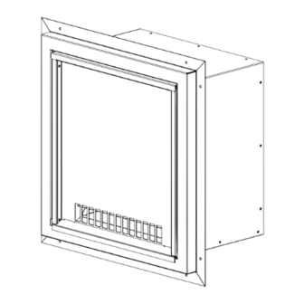
Specifications imensions 13.62 14.00 18.12 16.26 8.65 18.29 16.43 14.04 Figure 1: Power Head Dimensions ontents The table below outlines the complete contents of the Chase Comfort Kit (50-4175). Refer to the parts diagram section of this manual for reference and ensure that your kit is complete and undamaged. Table 1: Chase Comfort Kit Contents Part Description Power head w/ Finishing Face... - Page 3 Assembly ssembly Heat release not required if wiring Prior to installation, the finishing face should be Option 3 used (see page 13) installed onto the power head. See Figure 2 & Figure 3 below for directions. Refer to page 6, step 6 prior to setting the depth of the finishing face.
- Page 4 Installation - Enviro G-Series Restrictions WARNING: IT IS ESSENTIAL TO ACTIVATE THE FIREPLACE’S COOL SURFACE SYSTEM (CSS) PRIOR TO INSTALLATION TO ALLOW ADEQUATE AIRFLOW FOR THE CLEAN FINISH CHASE COMFORT KIT. FAILURE TO DO SO WILL CREATE A PRESSURIZED CHASE THAT COULD LEAD TO POTENTIAL BLOWER FAILURE OR BUILDING FIRE.
- Page 5 Installation - Power Head Restrictions & Clearances & C ower heAD estriCtions leArAnCes To determine the location of the power head refer to Figure 7 & Table 2 below. Note - The power head must be located within the same chase as the fireplace and can’t be attached to ducting/venting or installed in a separate bulkhead.
- Page 6 Installation - Power Head Framing 1. Determine the location of the power head as directed on the previous page. NOTE: The Chase Comfort Kit allows for a minimum wall thickness of 8” (203mm) and a maximum wall thickness of 12” (305mm).
- Page 7 Installation - Power Head Exterior Wall Cladding Seal gaps with Silicone Figure 12: Silicone Locations Figure 11: Power Head Installation 11. The exterior wall finishing material can now be installed around the power head. The finishing 7. Upon completion of Step 6, mount the finishing face material can butt up against the perimeter of the to the power head using eight (8) self-tapping screws.
-
Page 8: Remote Installation
Remote Installation emote nstAllAtion PtionAl The comfort kit can also be installed remotely via 5” flex venting (not supplied). 1. Install the power head making sure to follow the restrictions and clearances from the previous sections. 2. Determine the location for the 5” flex vent (not included) and cut a 5” diamater hole. *NOTE: The centerpoint of this hole can be a maximum of 8”... - Page 9 Power Head Wiring ower iring A 5 lead cable is included with the comfort kit to wire it to the fireplace. BX armored cable (not supplied), similar to furnace wiring, may also be used if desired. NOTE: The cable end with electrical quick connects attached is for wiring to the fireplace. The other end of the cable is for wiring the termination.
- Page 10 Wiring Power Head Wiring (Continued) 6. Reinstall the power head’s front cover. The fireplace must be electrically connected and grounded in accordance with local codes or, in the absence of local codes, with the current CSA C22.1 Canadian Electrical Code Part 1, Safety Standards For Electrical Installations, or The National Electrical Code ANSI / NFPA 70 in the US.
- Page 11 Wiring Option 1 - Wall Switch or Rheostat: *IMPORTANT - Chase must be contructed with a permitted heat release, see figure 19* Wall Switch / Rheostat - The Chase Comfort kit may be wired Rheostat 115VAC* directly to a wall switch for simple on/off control, or to a rheostat for variable speed control (see figure 20).
-
Page 12: Remote Control
Remote Control Fan Icon Activation (If Required): Figure 24: Step 3 Figure 23: Step 2 Figure 25: Step 4 Figure 22: Step 1 1. With no batteries inserted into the remote, keep pressed Power On/Off and O buttons. 2. Insert batteries into the remote while still pressing the two buttons. The following screen is displayed. Each icon can be: a. - Page 13 Clean Finish Wiring Option 3 - Automatic Non-Adjustable Control (Required for Clean Finish): This option MUST BE USED if a clean finish, non-heat release chase is desired. The fireplace will automatically operate the Comfort Kit at a set non-adjustable speed whenever the fireplace is turned on. All Urbana fireplaces come pre-wired to make installation as easy as possible.
- Page 14 Clean Finish Wiring Comfort Kit / PV Strain Relief Incoming 120VAC Strain Relief Figure 29: Power Vent Cable Strain Relief (U37/U44 models) Connecting the 5-Wire Cable: Refer to the wiring diagram (see Figure 31) while following the directions below. - Locate the unused BLACK lead on the green terminal block plugged into X12 on the IFC. Connect ower the BLACK cable lead to it.
- Page 15 Power Vent Mode 4. To switch the IFC into power vent (PV) mode locate the fireplace switch panel behind the right side panel on U37/U44 (see Figure 30). The far left / top rocker switch with the cover above it controls the mode setting of the IFC.
-
Page 16: Wiring Diagram
Wiring Diagram Top Light / lumière Valve / soupage supérieure PV or Comfort Kit Wires / l PV ou kit de confort Bare Wire Ends / extrémités dénudées des ls Fuse / Fusible 2A Switch Panel / Panneau de com- Pilot / mutation du foyer veilleuse... -
Page 17: Maintenance And Service
Maintenance & Service isChArge AmPer An external duct damper is NOT required with this kit. The Chase Comfort Kit is equipped with an internal sealing damper that closes whenever the blower is not in operation, sealing off the chase from the outside. Whenever the blower is turned on, air from the chase will flow out of the power head discharge automatically opening the damper. -
Page 18: Parts List
Parts List Table 3: Replacement Parts Reference Part Description Part Number Number Finishing Face 50-3770 Front Cover 50-3980 PV Blower Motor 50-3767 PV Vacuum Switch 50-3766 Framing Thimble Aseembly 50-3768 18 |... - Page 19 MANUFACTURED BY: SHERWOOD INDUSTRIES LTD. 6782 OLDFIELD RD. SAANICHTON, BC, CANADA V8M 2A3 www.Urbanafireplaces.com www.Enviro.com Spring 2022 C-16530 | 19...
Need help?
Do you have a question about the URBANA 50-4175 and is the answer not in the manual?
Questions and answers