Nordson Encore System Customer Product Manual
Mobile powder spray system with vibratory box feeder
Hide thumbs
Also See for Encore System:
- Customer product manual (139 pages) ,
- Installation, troubleshooting, repair (97 pages) ,
- Product manual (67 pages)
Table of Contents
Advertisement
Quick Links
r
Encore
Mobile Powder Spray
System with Vibratory Box Feeder
Customer Product Manual
Part 1102770_04
Issued 10/11
For parts and technical support, call the
Finishing Customer Support Center at (800) 433-9319.
This document is subject to change without notice.
Check http://emanuals.nordson.com/finishing for the latest version.
FM
C
US
APPROVED
NORDSON CORPORATION • AMHERST, OHIO • USA
Advertisement
Table of Contents
Troubleshooting

Related Manuals for Nordson Encore System


Summary of Contents for Nordson Encore System
- Page 1 Part 1102770_04 Issued 10/11 For parts and technical support, call the Finishing Customer Support Center at (800) 433-9319. This document is subject to change without notice. Check http://emanuals.nordson.com/finishing for the latest version. APPROVED NORDSON CORPORATION • AMHERST, OHIO • USA...
- Page 2 Notice Nordson Corporation welcomes requests for information, comments, and This is a Nordson Corporation publication which is protected by copyright. inquiries about its products. General information about Nordson can be Original copyright date 2009. No part of this document may be...
-
Page 3: Table Of Contents
......... 2-10 Part 1102770_04 E 2011 Nordson Corporation... - Page 4 ....... . . 4-12 Part 1102770_04 E 2011 Nordson Corporation...
- Page 5 ......... . 6-14 Part 1102770_04 E 2011 Nordson Corporation...
- Page 6 Table of Contents Part 1102770_04 E 2011 Nordson Corporation...
-
Page 7: Safety
Regulations and Approvals Make sure all equipment is rated and approved for the environment in which it is used. Any approvals obtained for Nordson equipment will be voided if instructions for installation, operation, and service are not followed. All phases of equipment installation must comply with all federal, state, and local codes. -
Page 8: Personal Safety
Clean, maintain, test, and repair equipment according to the instructions in your equipment documentation. Use only replacement parts that are designed for use with original equipment. Contact your Nordson representative for parts information and advice. Part 1102770_04 E 2011 Nordson Corporation... -
Page 9: Grounding
Disconnect and lock out electrical power. Close pneumatic shutoff valves and relieve pressures. Identify the reason for the malfunction and correct it before restarting the equipment. Disposal Dispose of equipment and materials used in operation and servicing according to local codes. Part 1102770_04 E 2011 Nordson Corporation... - Page 10 Safety Part 1102770_04 E 2011 Nordson Corporation...
-
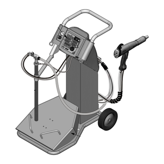
Page 11: System Setup
These components are shipped in individual boxes inside the system shipping container. Spray Gun Spray Gun Controller Pump Pickup Tube Vibrator Table Figure 2-1 Encore Mobile Powder Spray System with Vibratory Box Feeder Part 1102770_04 E 2011 Nordson Corporation... -
Page 12: Specifications
Input Air: 6.0−7.6 bar (87−110 psi), <5μ particulates, dew point <10 _C (50 _F) Max Relative Humidity: 95% non-Condensing Ambient Temperature Rating (Encore System): +15 to +40 _C (59−104 _F) Hazardous Location Rating for Applicator: Zone 21 or Class II, Division 1... -
Page 13: System Connections
The power unit houses a 24Vdc power supply, circuit board, and iFlowr air control manifold. The interface module houses the controller interface panel, which contains the displays and controls used to make controller function settings and spray settings. Part 1102770_04 E 2011 Nordson Corporation... - Page 14 (15 ft) (Manual System) or Auxiliary Vibrator Motor Power Cord Fluidizing Air INTERFACE MODULE Check Valve (8-mm, reduced to 6-mm) Ground Network/Power Interconnect Cable Gun Cable (to Gun) Figure 2-3 Encore Gun Controller Connections Part 1102770_04 E 2011 Nordson Corporation...
-
Page 15: Pickup Tube And Pump Installation
1A. Tube holder 4. 6-mm conductive black fluidizing air tubing 8. 8-mm black flow-rate air 2. Pickup tube catch tubing 5. Powder pump 3. Pickup tube assembly 9. Powder feed hose 6. Quick-connect fittings Part 1102770_04 E 2011 Nordson Corporation... -
Page 16: Spray Gun Connections
3. Thread the cable nut onto the receptacle and tighten the nut securely. Gun Cable Net Cable (To Power Unit) Figure 2-5 Connecting the Gun Cable to the Controller Interface Module Part 1102770_04 E 2011 Nordson Corporation... -
Page 17: Spray Gun Connections
5. Connect the 6-mm black purge air tubing to the purge air quick-disconnect fitting. 4-mm Clear Electrode Air Wash Tubing 6-mm Black Purge Air Tubing Figure 2-7 Connecting the Purge and Air Wash Tubing to the Controller Part 1102770_04 E 2011 Nordson Corporation... -
Page 18: Powder Feed Hose Connections
Use the sections of black spiral wrap supplied with the system to bundle together the spray gun cable, air tubing, and powder feed tubing. Coil the bundled tubing and cable and hang the coil on the hook at the back of the tower. Part 1102770_04 E 2011 Nordson Corporation... -
Page 19: System Air And Electrical Connections
The air must be clean and dry. A refrigerant or desiccant-type air drier and air filters are recommended. 10-mm Air Tubing Air Filter/ Regulator Figure 2-9 System Air Supply Connection Part 1102770_04 E 2011 Nordson Corporation... -
Page 20: Electrical Connections
N (neutral) Brown L (hot) Green/Yellow GND (ground) System Ground See Figure 2-10. Connect the ground cable attached to the power unit ground stud to a true earth ground. Figure 2-10 System Ground Connection Part 1102770_04 E 2011 Nordson Corporation... -
Page 21: Operation
Powder Box Installation on page 3-4 for instructions. 4. Make sure the spray gun is not triggered, then turn on controller power. The displays and icons on the controller interface and gun interface should light. Part 1102770_04 E 2011 Nordson Corporation... -
Page 22: Factory Set Presets
Max kV, 150 g/min (20 lb/hr) Max kV, 300 g/min (40 lb/hr) Select Charge 3 (deep recess), 150 g/min (20 lb/hr) 100* * Select Charge Mode settings are factory set and cannot be changed. Part 1102770_04 E 2011 Nordson Corporation... -
Page 23: Spray Gun Operation
Purging the Gun 1. See Figure 3-2. Point the gun into the booth and release the main trigger. 2. Press the Purge button. The purge will continue as long as you press the purge button. Part 1102770_04 E 2011 Nordson Corporation... -
Page 24: Standby Button
NOTE: Do not force the end of the pickup tube into the powder. Vibration and gravity will cause the pickup tube to sink into the powder. 4. Swing the pickup tube bracket out from under the pickup tube and slide the tube down into the powder. Part 1102770_04 E 2011 Nordson Corporation... -
Page 25: Fluidizing Air Operation
Standby or turn off controller power. To configure the system for a vibratory box feeder, change the VBF delay time, or set the vibrator motor to continuous operation, refer to Controller Configuration on page 3-19. Part 1102770_04 E 2011 Nordson Corporation... -
Page 26: Electrode Air Wash Operation
Do not bend the antenna wire. 5. Screw the nozzle nut onto the gun body clockwise until finger-tight. Nozzle Nut Flat Spray Nozzle Electrode Assembly Figure 3-6 Changing a Flat Spray Nozzle Part 1102770_04 E 2011 Nordson Corporation... -
Page 27: Changing Deflectors Or Conical Nozzles
6. Screw the nozzle nut onto the gun body clockwise until finger-tight. 7. Install a new deflector on the electrode assembly. Do not bend the electrode wire. Electrode Holder Electrode Assembly Deflector Nozzle Nozzle Nut Figure 3-7 Changing a Conical Nozzle Part 1102770_04 E 2011 Nordson Corporation... -
Page 28: Installing The Optional Pattern Adjuster Kit
4. If shutting down for the night or a longer period of time, move the power unit switch to the OFF position to shut off system power. 5. Perform the Daily Maintenance procedures on page 3-9. Part 1102770_04 E 2011 Nordson Corporation... -
Page 29: Daily Maintenance
OEM part number in the part description to ensure that you order the correct element. System Daily: Make sure the system is securely connected to a true earth ground before Grounds spraying powder. Periodically: Check all system ground connections. Part 1102770_04 E 2011 Nordson Corporation... -
Page 30: Using The Controller Interface
The setpoints reset to the minimum if increased past their maximum. Selecting a Setpoint to Change Changing a Selected Setpoint Figure 3-10 Selecting and Changing Setpoints The Setpoint Icons light to indicate the configured or selected setpoints. Part 1102770_04 E 2011 Nordson Corporation... -
Page 31: Help Codes
The Help icon lights if the maintenance timer is set and runs out. To reset the maintenance timer, press the View button. The Timer icon lights when the maintenance hours are displayed. While they are displayed, press the Enter button. Figure 3-12 Displaying Maintenance Hours Part 1102770_04 E 2011 Nordson Corporation... -
Page 32: Preset Overview
Mode 3 Figure 3-14 Select Charge Mode NOTE: If the operator tries to adjust kV or μA values while a Select Charge mode is selected, the controller will switch to Custom or Classic mode. Part 1102770_04 E 2011 Nordson Corporation... -
Page 33: Custom Mode
Use the Standard mode to set kV. In Standard mode you cannot set μA. 1. To set the kV setpoint, press the KV button. The button LED lights to show that kV is selected. Part 1102770_04 E 2011 Nordson Corporation... -
Page 34: Classic Afc Mode
Refer to Controller Configuration on page 3-19. When the gun is not triggered the μA setpoint is displayed. AFC Mode − μA Setpoint AFC Mode − Gun Triggered Figure 3-17 AFC Mode − Setpoint and Gun Triggered Displays Part 1102770_04 E 2011 Nordson Corporation... -
Page 35: Powder Flow Settings
The tables show that as you increase Total Flow powder velocity increases while the maximum Flow Air % remains the same. Conversely, for a given Total Flow setting, each increase in Flow Air % increases powder flow. Part 1102770_04 E 2011 Nordson Corporation... -
Page 36: Setting Smart Flow Setpoints
When the spray gun is triggered the displays show actual flows. Flow Air % Total Flow Air in M /HR or SCFM Figure 3-20 Smart Flow Mode − Flow Air % or Total Flow ∑ Part 1102770_04 E 2011 Nordson Corporation... -
Page 37: Smart Flow Settings − Metric Units
6.37 6.79 7.22 7.64 8.07 8.49 8.92 9.34 9.77 10.19 5.95 6.80 7.22 7.65 8.07 8.50 8.92 9.35 9.77 10.20 0.85 1.27 1.70 2.12 2.55 2.97 3.40 3.82 4.25 4.67 5.10 5.52 5.95 Flow Part 1102770_04 E 2011 Nordson Corporation... -
Page 38: Smart Flow Settings − English Units
4.00 4.25 4.50 4.75 5.00 5.25 5.50 5.75 6.00 3.50 4.00 4.25 4.50 4.75 5.00 5.25 5.50 5.75 6.00 0.50 0.75 1.00 1.25 1.50 1.75 2.00 2.25 2.50 2.75 3.00 3.25 3.50 SCFM Flow Part 1102770_04 E 2011 Nordson Corporation... -
Page 39: Classic Flow Mode Settings
When the spray gun is triggered the actual flows are displayed. Controller Configuration Opening the Function Menu and Making Settings Press and hold the Nordson button for 5 seconds. The Function/Help display lights to show the Function numbers and values. Use the Functions to configure the controller for your application. - Page 40 Total Hours View Only − Save/Restore/Reset 00=System Save, 01=System Restore, 02=Factory Reset Gun Display Brightness 00=Low, 01=Medium, 02=Maximum Number of Presets 01−20 presets NOTE: Refer to Section 4, Troubleshooting for the Zero Reset procedure. Part 1102770_04 E 2011 Nordson Corporation...
-
Page 41: Vibratory Box Feeder On Continuously
3. Set F06 to F06−On. The default setting is F06−30. To set it to On, rotate the knob counterclockwise to decrement the numbers past 0 to 4. Press Enter to set the value to On, then press the Nordson button to exit the Functions menu. - Page 42 3-22 Operation Part 1102770_04 E 2011 Nordson Corporation...
-
Page 43: Troubleshooting
These troubleshooting procedures cover only the most common problems. If you cannot solve a problem with the information given here, contact your local Nordson representative for help. Help Code Troubleshooting The Help icon in the Function/Help display lights if a problem occurs that the controller can sense. -
Page 44: Help Code Troubleshooting Chart
Refer to the controller wiring diagrams in this section. Check the wiring harness connection to J7 and the proportional valve solenoid. Check the solenoid operation. Replace the valve if the solenoid is not working. Continued.. Part 1102770_04 E 2011 Nordson Corporation... - Page 45 If the fault reoccurs, check for a bad trigger switch. EEPROM Data Version Software version has been changed. This code appears after Changed a software update. Clear the fault. It should not reappear. Continued.. Part 1102770_04 E 2011 Nordson Corporation...
- Page 46 0 with the gun triggered on and close to a part, check the gun cable or the gun power supply. When the gun is triggered on and kV is set >0, the μA display should always read >0. Part 1102770_04 E 2011 Nordson Corporation...
-
Page 47: General Troubleshooting Chart
Remove powder path if necessary and clean it. Electrode air wash flow too high Adjust the needle valve at the power unit to decrease the electrode air wash flow. Continued... Part 1102770_04 E 2011 Nordson Corporation... - Page 48 Perform the Gun Cable Continuity Test on page 4-11. NOTE: It may be possible to use the settings trigger as the main trigger until repairs are made. Set Function F08 to F08−05. Refer to page 3-19. Continued... Part 1102770_04 E 2011 Nordson Corporation...
- Page 49 Check powder inlet tube, elbow, and electrode support for impact fusion or debris. Clean as necessary with compressed air. Flow and atomizing air tubing Check flow and atomizing air tubing reversed routing and correct if incorrect. Continued... Part 1102770_04 E 2011 Nordson Corporation...
- Page 50 17. Gun flow % does not Total air set to zero If the total air is set to zero the flow increment, always 0 percent cannot be adjusted. Change the total flow to a non-zero number. Part 1102770_04 E 2011 Nordson Corporation...
-
Page 51: Re-Zero Procedure
1. At the power unit, disconnect the flow and atomizing air tubing and install 8-mm plugs in the output fittings. 2. Press the Nordson button for 5 seconds to display the controller functions. F00−00 is displayed. 3. Rotate the knob until F10−00 is displayed. -
Page 52: Spray Gun Power Supply Resistance Test
The resistance should be 19−21 megohms. If the resistance is out of this range replace the electrode assembly. 19−21 Megohms Figure 4-3 Electrode Assembly Resistance Test Part 1102770_04 E 2011 Nordson Corporation... -
Page 53: Gun Cable Continuity Test
CAN + WHITE J1−2 P1−2 V− BLACK J1−3 P1−3 2 CAN + J1−4 P1−4 4 V+ 4 V+ BARE SHIELD/DRAIN 2 CAN + J1−5 P1−5 3 V− 3 V− Figure 4-5 Controller Interconnect Cable Wiring Part 1102770_04 E 2011 Nordson Corporation... -
Page 54: System Wiring Diagrams
(BLACK) DC COM (RED) +24VDC (RED) +24VDC 3 (WHITE) DC COM (GREEN) 4 (GREEN) +24VDC 5 (GRAY) DRAIN 1 (RED) CAN− 2 (BLACK) CAN+ (GREEN W/YELLOW) (GREEN W/YELLOW) Figure 4-6 Power Unit Wiring Diagram Part 1102770_04 E 2011 Nordson Corporation... -
Page 55: Controller Interface Wiring
5 (YELLOW) FEEDBACK (WHITE) CAN+ (GREEN) CHASSIS (BLUE) CAN− (BLACK) DC COM 3 (BLACK) DC COM 4 (WHITE) CAN+ 5 (BLUE) CAN− 1 (GREEN) CHASSIS 2 (RED) +24VDC Figure 4-7 Controller Interface Wiring Diagram Part 1102770_04 E 2011 Nordson Corporation... - Page 56 4-14 Troubleshooting Part 1102770_04 E 2011 Nordson Corporation...
-
Page 57: Repair
Figure 5-1. 3. Align the trigger switch header with the display module receptacle and push on the header to connect it. Apply even pressure on the header to seal it tightly against the display module. Part 1102770_04 E 2011 Nordson Corporation... - Page 58 (new switch) Display Module and Cable J3 Connectors Adhesive Switch Support Pad Header Figure 5-1 Display Module Replacement 9. Display module 11. Bezel A. Ground wire connector 10. Hook 12. M3 x 35 screws Part 1102770_04 E 2011 Nordson Corporation...
-
Page 59: Power Supply Replacement
5. Gently fold the trigger switch ribbon cable and gun cable/display cable and tuck them back into the gun. 6. Reinstall the display module and hook. Align Ribs and Grooves Figure 5-2 Power Supply Replacement 6. Power supply 8. Bulkhead Part 1102770_04 E 2011 Nordson Corporation... -
Page 60: Trigger Switch, Gun Cable, And Handle Replacement
27. Ground pad 7. Gasket 16. Settings trigger 27A. M3 lockwasher 8. Bulkhead 17. Main trigger 27B. M3 x 6 screw 9. Display module 18. Trigger actuator 28. Cable (6 meter) 19. Retaining ring (cable) Part 1102770_04 E 2011 Nordson Corporation... -
Page 61: Gun Disassembly
6. See Figure 5-5. Grasp the handle in one hand and the gun body in the other. Press the thumbs of each hand together while pulling in opposite directions to separate the gun body from the handle. Figure 5-5 Separating Handle and Gun Body Part 1102770_04 E 2011 Nordson Corporation... - Page 62 (27). 13. See Figure 5-9. Separate the right and left handles (25, 26). 14. Remove the main trigger, settings trigger, and trigger actuator (16, 17, 18) from the right handle half. Part 1102770_04 E 2011 Nordson Corporation...
- Page 63 Completing Gun Disassembly 15. Trigger switch 19. Retaining ring 26. Left handle 16. Settings trigger 22. Handle base 27. Ground pad 17. Main trigger 23. Inlet tube 28. Gun cable 18. Actuator 25. Right handle Part 1102770_04 E 2011 Nordson Corporation...
-
Page 64: Gun Re-Assembly
Gusset Pivot Pin Tabs Bottom Flat Figure 5-10 Trigger Switch and Trigger Mounting 15. Trigger switch 18. Actuator 16. Settings trigger 25. Right handle half 17. Main trigger Part 1102770_04 E 2011 Nordson Corporation... - Page 65 (27) with the lockwasher and screw (27A, 27B). 9. See Figure 5-12. Hook the ground pad (27) behind the locator tabs on the rear of the handles and rotate the ground pad into position against the handle assembly. Part 1102770_04 E 2011 Nordson Corporation...
- Page 66 15. Route the trigger switch header, gun cable connectors, and display module ground connector through the bottom opening in the bulkhead. Power Supply Connector Cable Connectors Trigger Switch Header Bulkhead Locator Tabs Figure 5-13 Assembling Bulkhead and Routing Cables Part 1102770_04 E 2011 Nordson Corporation...
- Page 67 23. See Figure 5-3. Install the electrode assembly into the front of the gun body. Make sure the electrode is not bent or broken. 24. Install the nozzle on the electrode assembly, making sure the keys in the electrode assembly slide into the slots on the nozzle. Part 1102770_04 E 2011 Nordson Corporation...
-
Page 68: Interface Module Repair
Refer to Section 6, Parts for repair kits. External Enclosure Ground Internal Enclosure Ground Connect to 2A, J6 Figure 5-15 Interface Module Assembly 1. Bezel 2A. Main Control Board 2C. Keypad Panel 2. Keypad/PCB Assembly 2B. Main Display Board 3. Enclosure Part 1102770_04 E 2011 Nordson Corporation... -
Page 69: Power Unit Repair
Refer to Section 4, Troubleshooting, for the power unit electrical schematic and harness connections. Removing the Sub Panel External Enclosure Ground Internal Enclosure Gound Figure 5-16 Sub Panel Removal 1. Enclosure 2. Sub Panel 3. Power Switch Guard Part 1102770_04 E 2011 Nordson Corporation... -
Page 70: Sub Panel Components
(1) that supplies air to the iFlow module after replacing it. NOTE: The plugs and connectors in the regulator ports are not supplied with a replacement regulator. Re-use the plugs and fittings from the old regulator. Part 1102770_04 E 2011 Nordson Corporation... -
Page 71: Iflow Module Repair
3. Turn on the manometer. If desired, change the scale to read bar instead of psi. Refer to manometer documentation for instructions. 4. Point the spray gun into the booth and trigger the gun on. Part 1102770_04 E 2011 Nordson Corporation... - Page 72 Troubleshooting procedures in Section 4, Troubleshooting. Orifice Assembly Figure 5-18 Air Verification Kit Usage 1. Manometer 4. Orifice 2. Clear 4-mm tubing 5. Tee 3. 4-mm tube connector 6. 8-mm quick disconnect adapter Part 1102770_04 E 2011 Nordson Corporation...
-
Page 73: Flow To Pressure Chart
The valves are calibrated for different springs. 3. Remove the valve stem (8) from the valve body (11). 4. Remove the valve cartridge (10) and spring (9) from the stem. Part 1102770_04 E 2011 Nordson Corporation... - Page 74 7. Direction of flow arrow 11. Valve body 3. Coil−proportional valve (2) 8. Stem 12. Orifice 4. Long screws−valve to manifold (2) 9. Spring 13. Solenoid valves 5. Short screws−valve stem to body (2) Part 1102770_04 E 2011 Nordson Corporation...
-
Page 75: Proportional Valve Replacement
3. Support the arm assembly and remove the two screws from the top of the arm mount. 4. Install the new arm assembly with the two screws included with the assembly. 5. Re-install the cover, then the handle. Part 1102770_04 E 2011 Nordson Corporation... - Page 76 5-20 Repair Pickup Tube Arm Assembly Replacement (contd) Arm Screws Cover Screws Handle Screws Figure 5-20 Arm Assembly Replacement Part 1102770_04 E 2011 Nordson Corporation...
-
Page 77: Parts
Section 6 Parts Introduction To order parts, call the Nordson Finishing Customer Support Center at (800) 433-9319 or contact your local Nordson representative. This section covers parts for the spray gun, controller, and mobile system. Refer to the following manuals for additional information and optional equipment. -
Page 78: Spray Gun Parts
Parts Spray Gun Parts Figure 6-1 Exploded View of Encore Manual Spray Gun and Accessories Part 1102770_04 E 2011 Nordson Corporation... - Page 79 S HANDLE, ground pad, handgun, Encore 983520 S WASHER, lock, internal, M3, zinc 982427 S MACHINE SCREW, pan head, recessed, M3 x 6, zinc 1102625 S CABLE ASSEMBLY, handgun, 6 meter 1083206 S DEFLECTOR assembly, conical, 26 mm Continued... Part 1102770_04 E 2011 Nordson Corporation...
- Page 80 E: Use to secure and seal trigger switch header to display module. F: Also available in wear or impact resistant materials. Refer to Options. G: Available in 1102653 Kit, Upgrade, handgun, Encore to upgrade older guns to 1102650 gun configuration. Part 1102770_04 E 2011 Nordson Corporation...
-
Page 81: Spray Gun Options
The 4-mm flat spray nozzle is shipped with the spray gun. All other flat spray nozzles are optional. 1081656 1081657 2.5 mm Flat Spray 3 mm Flat Spray 1081659 1081658 4 mm Flat Spray 6 mm Flat Spray Figure 6-2 Flat Spray Nozzles Part 1102770_04 E 2011 Nordson Corporation... -
Page 82: Conical Nozzle And Deflectors
Conical Nozzle 16-mm Deflector 19-mm Deflector 26-mm Deflector 38-mm Deflector Figure 6-3 Conical Nozzle and Deflectors Cross Cut Nozzles 1082184 1082185 1082186 60 Degree Cross-cut 90 Degree Cross-cut 2.5 mm Castle Figure 6-4 Cross-cut Nozzles Part 1102770_04 E 2011 Nordson Corporation... -
Page 83: Pattern Adjuster Kit
The pattern adjuster kit includes an integral conical nozzle. 16, 19, and 26-mm deflectors can be used with the kit. The deflectors are not included with the kit; they must be ordered separately. 1098417 Kit, Pattern Adjuster, Manual Gun, Encore Figure 6-5 Pattern Adjuster Kit Part 1102770_04 E 2011 Nordson Corporation... -
Page 84: Controller Parts
Parts Controller Parts Interface Unit Parts Illustration Figure 6-6 Interface Parts Part 1102770_04 E 2011 Nordson Corporation... -
Page 85: Interface Unit Parts List
1082709 S RECEPTACLE, gun, Encore 1082759 S RECEPTACLE, net, controller interface, Encore 1080719 CABLE, interface/controller, 30 in. NOTE A: Receptacles include harnesses B: Cable is not included with interface. Order replacements separately. Part 1102770_04 E 2011 Nordson Corporation... -
Page 86: Power Unit Parts Illustration
6-10 Parts Power Unit Parts Illustration Figure 6-7 Power Unit Parts Part 1102770_04 E 2011 Nordson Corporation... -
Page 87: Power Unit Parts List
E: Only use this capacitor with the 115V power unit (1600468) using a 115 V motor with a model number of MVE21M. If the 115 V motor is MVE20, then the 2.0 μF capacitor is acceptable. AR: As Required Part 1102770_04 E 2011 Nordson Corporation... -
Page 88: Iflow Module Parts
972399 S CONNECTOR, male, w/internal hex, 6 mm tube x in. unithread 972125 S CONNECTOR, male, elbow, 10 mm tube x in. unithread 1082612 S VALVE, flow control, 4 mm x 1/8 in. unithread Part 1102770_04 E 2011 Nordson Corporation... -
Page 89: System Components And Parts
I: For motors with a model number of MVE21M, a 4.0 μF capacitor (1600471) must be used in the controller power unit. If the motor model number is MVE20, then a 2.0 μF capacitor (1083021) is acceptable. NS: Not Shown Part 1102770_04 E 2011 Nordson Corporation... -
Page 90: Powder Hose And Air Tubing
C: Use this bracket to install two pickup tubes on the arm assembly. Pump Parts Each Encore pump is shipped with a manual. Encore pump manuals can also be downloaded from http://emanuals.nordson.com/finishing. Encore Generation II Powder Feed Pump Encore Generation I Powder Feed Pump... -
Page 91: Declaration Of Conformity
- SIRA08ATEX5010X (Eccleston, Chester, UK) ATEX Surveillance: - 1180 Baseefa (Buxton, Derbyshire, UK) Date: 09 March 2010 Mike Hansinger Manager Engineering Development Industrial Coating Systems Nordson Authorized Representative in the EU Contact: Operations Manager Industrial Coating Systems Nordson Deutschland GmbH Heinrich-Hertz-StraBe 42-44 D-40699 Erkrath...
Need help?
Do you have a question about the Encore System and is the answer not in the manual?
Questions and answers