Nordson Encore Customer Product Manual
Engage gateway
Hide thumbs
Also See for Encore:
- Customer product manual (139 pages) ,
- Installation, troubleshooting, repair (97 pages) ,
- Product manual (67 pages)
Table of Contents
Advertisement
Quick Links
Download this manual
See also:
Customer Product Manual
Encorer Engage Gateway
Customer Product Manual
Part 1615959−01
Issued 03/19
For parts and technical support, call the
Finishing Customer Support Center at (800) 433-9319.
This document is subject to change without notice.
Check http://emanuals.nordson.com for the latest version.
NORDSON CORPORATION • AMHERST, OHIO • USA
Advertisement
Table of Contents

Subscribe to Our Youtube Channel
Related Manuals for Nordson Encore


Summary of Contents for Nordson Encore
- Page 1 Customer Product Manual Part 1615959−01 Issued 03/19 For parts and technical support, call the Finishing Customer Support Center at (800) 433-9319. This document is subject to change without notice. Check http://emanuals.nordson.com for the latest version. NORDSON CORPORATION • AMHERST, OHIO • USA...
-
Page 2: Table Of Contents
......Contact Us Notice This is a Nordson Corporation publication which is protected by copyright. Nordson Corporation welcomes requests for information, comments, and Original copyright date 2019. No part of this document may be inquiries about its products. - Page 3 Change Record Change Record Revision Date Change 03/19 New Release. Part 1615959−01 E 2019 Nordson Corporation...
- Page 4 Change Record Part 1615959−01 E 2019 Nordson Corporation...
-
Page 5: Safety
Regulations and Approvals Make sure all equipment is rated and approved for the environment in which it is used. Any approvals obtained for Nordson equipment will be voided if instructions for installation, operation, and service are not followed. All phases of equipment installation must comply with all federal, state, and local codes. -
Page 6: Personal Safety
Clean, maintain, test, and repair equipment according to the instructions in your equipment documentation. Use only replacement parts that are designed for use with original equipment. Contact your Nordson representative for parts information and advice. Part 1615959−01 E 2019 Nordson Corporation... -
Page 7: Grounding
Disconnect and lock out electrical power. Close pneumatic shutoff valves and relieve pressures. Identify the reason for the malfunction and correct it before restarting the equipment. Disposal Dispose of equipment and materials used in operation and servicing according to local codes. Part 1615959−01 E 2019 Nordson Corporation... -
Page 8: Description
For a system with the maximum of 32 spray guns, there are 16 KV nodes and 16 flow nodes connected on a CAN network. The system is compatible with Encorer and Encore HD automatic guns. Spray Gun Main System Controller:... -
Page 9: Installation
A Gateway mounted into a single-slot package, mounted in a custom electrical enclosure (see page 40). External/Auxiliary Controller Slots 1 −8 reserved for Sub Panel Dual Gun Driver PCAs Card Cage Slot 9 for Gateway Figure 2 Installing Gateway into External/Auxiliary Controller Part 1615959−01 E 2019 Nordson Corporation... -
Page 10: Electrical Power
Fieldbus Connection The fieldbus connection is made directly to the Anybusr support board, which is mounted to the Gateway board. The customer must provide the appropriate cable for PROFINET or EtherNet/IP networks. Part 1615959−01 E 2019 Nordson Corporation... -
Page 11: Gateway Pca (Printed Circuit Assembly) Board Jumper Settings
Default Position−Not Used All “Open” (Shown) DIP Switch SW1: (Jumper placed on Pin 1 Only) All “Open” (Shown) See SW2 Configurations in Table 17 on Page 39. 10013409−02 Figure 3 Gateway PCA Board Jumper Settings Part 1615959−01 E 2019 Nordson Corporation... -
Page 12: Software
CAN network of several intelligent powder flow (either HDLVr or Venturi) and gun KV control modules Since the Encore Engage system uses separate intelligent modules (or nodes) for controlling powder flow and gun voltage, the PLC must have the capability to communicate to two nodes for controlling a single gun. -
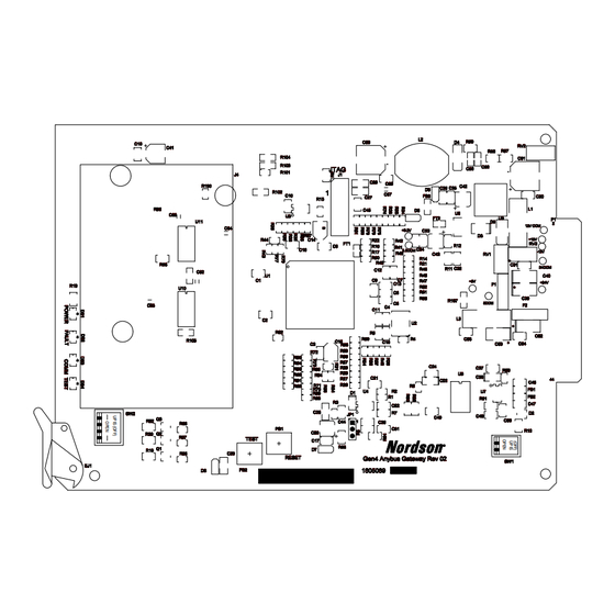
Page 13: Hardware Requirements
Edge-Connector to Card Cage Address Backplane Anybus-S board Ethernet Data with RJ45 Ethernet Cable to PLC Connector Control Cable to Engage Interface Control Nodes Slot 9 Gateway Board Figure 4 Encore Engage Gateway PCA Diagram Part 1615959−01 E 2019 Nordson Corporation... -
Page 14: Gateway Software
CAN bus Fieldbus Interface Interface Hardware Hardware Fieldbus S-Module CPU/ Firmware DSP Firmware Module Dual Port Memory (which converts dual port memory data into CAN messages and vice versa) Figure 5 Gateway Software Modules Part 1615959−01 E 2019 Nordson Corporation... -
Page 15: Software Version
FAULT COMM TEST 10013409_01 Figure 6 Location of LEDs on Anybus-S Board for Version Verification Table 1 LEDs to Version Conversion Chart LED Label LED Color Position TEST Green COMM Yellow FAULT Part 1615959−01 E 2019 Nordson Corporation... -
Page 16: Addressing Modes
Sends commands and data from the PLC to an individual gun control node (most commonly Set Preset Message) Send messages from the gun control nodes to the PLC (includes Gun Monitor Message and System Status Message) Part 1615959−01 E 2019 Nordson Corporation... -
Page 17: Io Image Table Configuration
NOTE: For a successful Gateway setup, the PLC programmer should be familiar with the proprietary Nordson CAN protocol. The direction of the data (input or output) is from the PLC’s reference point. The secondary is configured at the factory to have the following 29 IO modules shown in Table 2. -
Page 18: Nordson Corporation
D: 1 byte for each of the guns in the system (maximum of 32 guns in a system). E: Gun number displayed depends on page number value in IO Module 4. F: Page number is defined by the value of the second byte in IO Module 9. Part 1615959−01 E 2019 Nordson Corporation... -
Page 19: Io Image Table − Module Definitions
Before setting new KV or flow parameter values, clear the first byte of IO Module 3 to 0. After new values are written, set the first byte to 1. Part 1615959−01 E 2019 Nordson Corporation... -
Page 20: Nordson Corporation
IO Module 3 is reserved for the efficient handling of Data Table 5 and to quickly send these parameters to their respective nodes. IO Module 7 is provided primarily to send out other Data Tables as unicast messages. Part 1615959−01 E 2019 Nordson Corporation... -
Page 21: Nordson Corporation
IO Module 28. The value of 0 is for Guns 1−16; value of 1 is for Guns 17−32. All of the IO Modules are discussed in more detail in later sections. Part 1615959−01 E 2019 Nordson Corporation... -
Page 22: Nordson Corporation
When NFC is not used, μA is 1 count per μA. If NFC is used and μA setpoint is less than 10 μA , then the value in Address Offset 18 is 1 count per 0.1 μA. This value is entered with no decimal point (an integer) and made a negative number. Continued... Part 1615959−01 E 2019 Nordson Corporation... -
Page 23: Nordson Corporation
Flow Node Maintenance Minutes (low byte of IO Module 16, high byte will be 0) Gun Node Firmware Version Flow Node Firmware Version HDLV Pump Lookup Table Gateway S/W Version Reserved Reserved Reserved Reserved Pump States 14−255 Spare Part 1615959−01 E 2019 Nordson Corporation... -
Page 24: Nordson Corporation
IO Module 26. Address Offset 196 is used to determine the communication status between Gateway and the Nodes. This byte is updated within 5 seconds if the Gateway receives any message from any of the Nodes. Part 1615959−01 E 2019 Nordson Corporation... -
Page 25: Nordson Corporation
IO Module 28 to 0 (WAIT state), all the data in IO Module 28 will reset to 0. The PLC program has to request the information data again to get the updated values. Part 1615959−01 E 2019 Nordson Corporation... -
Page 26: Nordson Corporation
Alarm State Global Status Flags 0−32 Communication Fault Global Status Flags 0−32 No 24 Vdc Fault Communication Status 0−255 Gateway−Nodes Communication Status Current Page Number 0−1 198−199 Future Use Heartbeat 0−255 Heartbeat from Secondary Continued... Part 1615959−01 E 2019 Nordson Corporation... -
Page 27: Nordson Corporation
Flow nodes 1−8 0−255 Each bit represents a Heartbeat Status node (2 guns). LSB is node 1 Flow nodes 9−16 0−255 Each bit represents a Heartbeat Status node (2 guns). LSB is node 1 Part 1615959−01 E 2019 Nordson Corporation... -
Page 28: Sending Messages From The Plc
3. When writing of the remaining bytes is complete, go back and write the first byte from the zero (WAIT) to its correct value. NOTE: The multiple scan method is recommended for output IO Modules 2, 3, 5, and 7. Part 1615959−01 E 2019 Nordson Corporation... -
Page 29: (Io Module 1)
Scan 2 Write all bytes of the of IO Module Scan 1 IO Module Set the”Wait” byte to a Scan 3 non-zero value Done Single Scan Method Done Multiple Scan Method Figure 7 Sending Messages Part 1615959−01 E 2019 Nordson Corporation... - Page 30 Gun Pulses 1−99 1 pulse Siphon Pulses 2−99 1 pulse Pulse On 2−20 50 milliseconds Pulse Off 2−20 50 milliseconds Siphon Pulse High 1−15 25 milliseconds Nibble Siphon Pulse Low 1−15 25 milliseconds Nibble Part 1615959−01 E 2019 Nordson Corporation...
- Page 31 Message 39 − Enable Spectrum HD Cleaning Mode This message places the specified spray gun in Spectrum HD mode. Spray guns can be individually activated by setting the corresponding bit or they can be deactivated by clearing them. Part 1615959−01 E 2019 Nordson Corporation...
-
Page 32: Multicast Messages From The Plc
A given preset’s parameters may be changed while a gun is triggered ON at that preset, so that elaborate flow variations onto a part are possible, if desired. Part 1615959−01 E 2019 Nordson Corporation... -
Page 33: Nordson Corporation
When NFC is not used, μA is 1 count per μA. If NFC is used and μA setpoint is less than NOTE A: 10 μA , then the value in Address Offset 18 is 1 count per 0.1 μA. This value is entered with no decimal point (an integer) and made a negative number. Part 1615959−01 E 2019 Nordson Corporation... -
Page 34: Nordson Corporation
Using IO Module 7 of the Output Image Table This IO module uses the data in Address Offsets #32 and #33 to determine the CAN address of the destination node/channel which needs to receive the unicast message. Part 1615959−01 E 2019 Nordson Corporation... -
Page 35: Flow % Adjust Message
%Adjust value sent to them. The Gateway sends a broadcast message to each channel of each flow control node every time the PLC sends a Flow % Adjust message. Part 1615959−01 E 2019 Nordson Corporation... -
Page 36: Reading Data At The Plc − Input Image Table
Gun Page Number value written by the PLC to IO Module 4 of the Output Image Table. Use Tables 5, 9, and 10 to identify the correct Address Offsets within the IO modules for the desired function. Part 1615959−01 E 2019 Nordson Corporation... -
Page 37: Nordson Corporation
Stores the current gun type connected to the physical gun channel. Valid Gun Codes: Gun Type 0 = No Gun 6 = Encore and Encore HD See Table 12. KV Faults Contains any fault bits which have been detected by the gun’s KV node. -
Page 38: Nordson Corporation
The first two bits indicate the state of the KV and Flow nodes regarding their lockout state. General Status When Lockout is ON, the gun cannot be trigger ON. Use Table 14 for bit definitions. Part 1615959−01 E 2019 Nordson Corporation... -
Page 39: Nordson Corporation
14 or 30 15 or 31 16 or 32 Actual KV Actual uA Preset − KV KV Status Bits Gun Type KV Faults Actual Flow/Pattern Actual Atomizing/Assist Preset Flow Flow Status Bits Flow Faults General Status Part 1615959−01 E 2019 Nordson Corporation... -
Page 40: Nordson Corporation
1=Faulted Fold Back 0=No Fault 1=Faulted Feed Back 0=No Fault 1=Faulted Open Circuit 0=No Fault 1=Faulted Short Circuit 0=No Fault 1=Faulted Hardware 0=No Fault 1=Faulted Alarm (Any) 1=Alarm ON No 24V 1=No 24V Supply Part 1615959−01 E 2019 Nordson Corporation... -
Page 41: Nordson Corporation
DLL Mode Bit 1 Gun Operating Mode DLL Mode Bit 2 Gun Operating Mode DLL Mode Bit 3 7 (MSB) Note: The Gun Operating Mode can have the following values: 0=STD 1 thru 9=DLL No. 10=Tribo Part 1615959−01 E 2019 Nordson Corporation... -
Page 42: General System Status
Function Range Guns w/Lockout ON 0−32 (0=None) uns w/Alarm 0−32 (0=None) Guns 0−32 (0=None) w/Communication Fault Guns w/No 24 VDC 0−32 (0=None) Fault Gateway−Node 0−255 Communication Status Current Page No. 0−1 198−199 Future Use Part 1615959−01 E 2019 Nordson Corporation... -
Page 43: Gateway Heartbeat
Table 17 Dip Switch (SW2) Settings NOTE: By default, all positions are OPEN. Switch Function Open Closed SW2-4 Byte Swapping Disabled Enabled SW2-3 Communication Normal Listen Only SW2-2 Mode Engage Not Used SW2-1 Pump Type Venturi HDLV Part 1615959−01 E 2019 Nordson Corporation... -
Page 44: Parts
Encorer Engage Gateway Parts To order parts, call the Nordson Finishing Customer Support Center at (800) 433-9319 or contact your local Nordson representative. For more information, go to http://www.nordson.com on the Internet. Gateway Replacement Parts NOTE: All kits include the host PCA and Anybus-S module.
Need help?
Do you have a question about the Encore and is the answer not in the manual?
Questions and answers