Table of Contents
Advertisement
Quick Links
KIT_XMC14_2Go user guide
About this document
Scope and purpose
This document describes the features and hardware details of the KIT_XMC14_2GO equipped with the ARM®
Cortex™-M0 based XMC1400 microcontroller from Infineon Technologies AG.
Intended audience
This document is intended for users who use the KIT_XMC14_2GO.
Table of contents
About this document ....................................................................................................................... 1
Table of contents ............................................................................................................................ 1
1
Overview ............................................................................................................................... 2
1.1
Key features ............................................................................................................................................. 2
1.2
Block diagram .......................................................................................................................................... 3
2
Hardware description ............................................................................................................. 4
2.1
Power supply ........................................................................................................................................... 5
2.2
Pin header connector .............................................................................................................................. 5
2.3
User LEDs ................................................................................................................................................. 6
2.4
Reset ........................................................................................................................................................ 6
2.5
Debugging and UART communication ................................................................................................... 6
2.6
CAN Bus .................................................................................................................................................... 7
3
Production Data ..................................................................................................................... 8
3.1
Schematics .............................................................................................................................................. 8
3.2
Components placement and geometry ................................................................................................. 9
3.3
List of material ......................................................................................................................................... 9
User Guide
www.infineon.com
page 1 of 12
V1.0
2024-07-29
Advertisement
Table of Contents

Related Manuals for Infineon KIT XMC14 2Go


Summary of Contents for Infineon KIT XMC14 2Go
-
Page 1: Table Of Contents
About this document Scope and purpose This document describes the features and hardware details of the KIT_XMC14_2GO equipped with the ARM® Cortex™-M0 based XMC1400 microcontroller from Infineon Technologies AG. Intended audience This document is intended for users who use the KIT_XMC14_2GO. -
Page 2: Overview
KIT_XMC14_2GO user guide Overview Overview The KIT_XMC14_2GO is designed to evaluate the capabilities of the XMC1400 microcontroller with the free of charge tool chain ModusToolbox™ and Arduino IDE. This board is not cost optimized and does not serve as a reference design. Key features Table 1 summarizes the features of the KIT_XMC14_2GO. -
Page 3: Block Diagram
KIT_XMC14_2GO user guide Overview Block diagram The block diagram in Figure 1 shows the main components of the Kit KIT_XMC14_2GO including the power supply concept. There are the following main building blocks: XMC1400 microcontroller in a 5 x 5 mm VQFN-40 package ... -
Page 4: Hardware Description
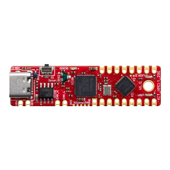
KIT_XMC14_2GO user guide Hardware description Hardware description The following sections give a detailed description of the board hardware and how it can be used. Figure 2 shows the components of the KIT_XMC14_2GO. Figure 2 Top view of KIT_XMC14_2GO The KIT_XMC14_2GO has also some components on the back of the platine which are shone in Figure 3. Figure 3 Back view of KIT_XMC14_2GO User Guide... -
Page 5: Power Supply
KIT_XMC14_2GO user guide Hardware description Power supply The KIT_XMC14_2GO can be powered by the USB-C connection with 5V. With the preprogrammed application and the onboard debugger in operation the KIT_XMC14_2GO typically draws about 85 mA. An onboard reverse current protection diode D101 will ensure safe operation and protects the USB port of the Laptop/PC in case power is provided through the pin header X1. -
Page 6: User Leds
KIT_XMC14_2GO user guide Hardware description In addition to the X1 pin header, the KIT_XMC14_2GO is equipped with four additional pins. These include Vin and GND, which can be supplied with an even higher external voltage. There is also a pin for CAN Low and CAN High, which are also shown in the pinout diagram in Figure 4. -
Page 7: Can Bus
The KIT_XMC14_2GO is provided with a CAN bus system. It uses CAN node 0 on RXD pin P1.1 and TXD pin P1.0 of the XMC1400. The High-Speed CAN Transeiver is TLE9351VSJ from Infineon which is used in CAN system for automotive applications as well as for industrial applications. -
Page 8: Production Data
KIT_XMC14_2GO user guide Production Data Production Data Schematics The schematic of the KIT_XMC14_2GO can be found in Figure 7. Figure 7 Schematic of the KIT_XMC14_2GO User Guide 8 of 12 V1.0 2024-07-29... -
Page 9: Components Placement And Geometry
KIT_XMC14_2GO user guide Production Data Components placement and geometry Figure 8 Layout and geometry List of material The list of material is valid for the KIT_XMC14_2GO version 1. Table 4 List of material Value Device Reference designator 100nF 50V 0402 10% X5R CER Capacitor C1, C2, C3, C4, C101, C102, C103, C104, C105, C106, C201... - Page 10 D101 PGB102ST23WR Diode D102 NSR0530HT1G Diode D201 XMC1404-Q040X0200 Microcontroller, XMC1404, Cortex M0, Infineon TLE9351BVSJ CAN transceiver, Infineon IC2 XMC4200_QFN48 Microcontroller, IC101 XMC4200, Cortex M4F, Infineon TLS205B0LD V50 Linear Voltage Regulator, IC200 Vout = 5V, Infineon TLS205B0EJV33 Linear Voltage Regulator, IC201 Vout = 3.3V, Infineon...
- Page 11 KIT_XMC14_2GO user guide Production Data Revision history Document Date of release Description of changes version Initial release User Guide 11 of 12 V1.0 2024-07-29...
- Page 12 Do you have a question about this Except as otherwise explicitly approved by Infineon information given in this application note. Technologies in a written document signed by...
Need help?
Do you have a question about the KIT XMC14 2Go and is the answer not in the manual?
Questions and answers