Table of Contents
Advertisement
Quick Links
r e s t r i c t e d
KIT-FPG1-T2G-B-E-2M automotive
f i n g e r p r i n t e v a l u a t i o n k i t g u i d e
About this document
Scope and purpose
This document provides information on how to use the Infineon fingerprint evaluation kit
(KIT-FPG1-T2G-B-E-2M). The kit consists of an Infineon fingerprint evaluation board designed to work with the
Infineon fingerprint match module, the Infineon fingerprint sensor module, and the software used to evaluate
the hardware.
Intended audience
This document is intended for anyone who uses it to evaluate the Infineon fingerprint sensor.
Document conventions
Convention
Bold
Abbreviations and definitions
Abbreviation
CAN
CMSIS
DAP
EVB
FPG
FPMM
FPSM
GPIO
GUI
LIN
SPI
UART
USB
User Guide
www.infineon.com
Explanation
Emphasizes heading levels, column headings, table and figure captions, screen names,
windows, dialog boxes, menus and sub-menus
Definition
Controller Area Network
Common Microcontroller Software Interface Standard
Debug Access Point
Evaluation Board
Fingerprint
Fingerprint Matcher Module
Fingerprint Sensor Module
General Purpose Input Output
Graphical User Interface
Local Interconnect Network
Serial Peripheral Interface
Universal Asynchronous Receiver Transmitter
Universal Serial Bus
Please read the Important Notice and Warnings at the end of this document
page 1 of 37
002-36609 Rev. **
2022-11-07
Advertisement
Table of Contents

Subscribe to Our Youtube Channel
Related Manuals for Infineon KIT-FPG1-T2G-B-E-2M


Summary of Contents for Infineon KIT-FPG1-T2G-B-E-2M
-
Page 1: About This Document
This document provides information on how to use the Infineon fingerprint evaluation kit (KIT-FPG1-T2G-B-E-2M). The kit consists of an Infineon fingerprint evaluation board designed to work with the Infineon fingerprint match module, the Infineon fingerprint sensor module, and the software used to evaluate the hardware. -
Page 2: Table Of Contents
Appendix C: Schematics for KIT-FPG1-T2G-B-E-2M ........ -
Page 3: Introduction
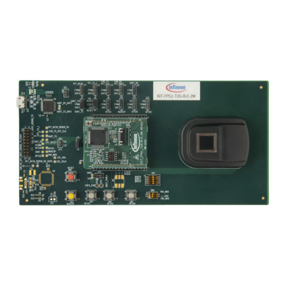
KIT-FPG1-T2G-B-E-2M automotive fingerprint evaluation kit guide Introduction Introduction This user guide describes the evaluation board (KIT-FPG1-T2G-B-E-2M) details and other components of the kit can be found in their respective user guides or datasheets. Table 1-1. Contents – Infineon fingerprint kit... - Page 4 KIT-FPG1-T2G-B-E-2M automotive fingerprint evaluation kit guide Introduction Figure 1-2. EVB - Top view User Guide 4 of 37 002-36609 Rev. ** 2022-11-07...
-
Page 5: Overview
FPMM connector pins that run to the FPSM. In this mode, the host processor of choice is running the Infineon embedded framework software to be able to communicate with the FPSM. Details of this mode are provided in “Direct FPSM connection to host”... - Page 6 KIT-FPG1-T2G-B-E-2M automotive fingerprint evaluation kit guide Overview Table 2-1. EVB functions (continued) Function Specification Notes Typical UART- Direct UART to USB bridge HOST settings (DEFAULT) RESET SWITCH Reset switch SW1. See – – “RESET switch and RESET select header”...
- Page 7 KIT-FPG1-T2G-B-E-2M automotive fingerprint evaluation kit guide Overview Table 2-1. EVB functions (continued) Function Specification Notes Typical UART- Direct UART to USB bridge HOST settings (DEFAULT) WAKEUP Select the source of the Wakeup J10. See Connect 2-3 Connect 1-2 SELECT HEADER signal “WAKEUP...
-
Page 8: Block Diagram
KIT-FPG1-T2G-B-E-2M automotive fingerprint evaluation kit guide Overview Block diagram Figure 2-1. Block diagram User Guide 8 of 37 002-36609 Rev. ** 2022-11-07... -
Page 9: Connection And Settings
KIT-FPG1-T2G-B-E-2M automotive fingerprint evaluation kit guide Connection and settings Connection and settings This section describes the various switches and headers available on the EVB. Confirm the settings are according to the intended use or if using the EVB without modifications confirm the header jumpers and switches are at default state as indicated in the following sub-sections before turning on the power supply or connecting the USB cable. -
Page 10: Reset Switch And Reset Select Header
KIT-FPG1-T2G-B-E-2M automotive fingerprint evaluation kit guide Connection and settings RESET switch and RESET select header The reset switch is a push button used to RESET the FM4 device on the FPMM. This reset signal is connected to the XINIT signal of the FPMM. The reset is an active low reset. The XINIT pin of FPMM can be driven from either the push button reset switch SW 1 or the expansion connector J16. -
Page 11: Usb-To-Uart Bridge (Cmsis-Dap -Fm3)
KIT-FPG1-T2G-B-E-2M automotive fingerprint evaluation kit guide Connection and settings USB-to-UART Bridge (CMSIS-DAP -FM3) The FM3 processor (U1) on the EVB performs the function of a USB-to-UART Bridge chip. The FM3 processor comes programmed with the correct firmware to perform the UART-to-USB bridging function. The MD0 pin of the FM3 part requires to be in the normal mode of operation when not programming this controller. -
Page 12: Fpmm And Fpsm Connections
KIT-FPG1-T2G-B-E-2M automotive fingerprint evaluation kit guide Connection and settings FPMM and FPSM connections The FPMM and FPSM modules are plugged into the EVB to form the embedded fingerprint system solution. The FPMM module is a PCB with a single in-line header on each side that plugs into the 17-pin headers (J14, J18) on the EVB. - Page 13 KIT-FPG1-T2G-B-E-2M automotive fingerprint evaluation kit guide Connection and settings Table 3-4. RESET select header configuration (continued) J18 pin# Signal name ZIF_SPI_CS ZIF_SPI_CLK Table 3-5. RESET select header configuration J17 pin# Signal name ZIF_XRES ZIF_INT ZIF_SPI_MISO ZIF_SPI_CS ZIF_SPI_CLK ZIF_SPI_MOSI ZIF_V3P3_CONN...
-
Page 14: Boot Switches
KIT-FPG1-T2G-B-E-2M automotive fingerprint evaluation kit guide Connection and settings BOOT switches Not supported in this kit. WAKEUP switches and WAKEUP select header The wakeup push button switch (SW4) is used to wake up the FPMM from a low-power mode. This push button is used to provide a wakeup signal to the VBAT_wakeup pin of the FPMM. -
Page 15: Gpio Switches And Gpio Select Headers
KIT-FPG1-T2G-B-E-2M automotive fingerprint evaluation kit guide Connection and settings GPIO switches and GPIO select headers Note: GPIO functionality is not available in this revision. Configure the GPIO switches on the EVB to perform various input/output functions according to the firmware configuration used. - Page 16 KIT-FPG1-T2G-B-E-2M automotive fingerprint evaluation kit guide Connection and settings Table 3-10. GPIO1 select header connection GPIO1 select header connection (J11) Function GPIO1 connected to expansion connector J16 GPIO1 connected to push button switch SW6 Table 3-11. GPIO2 select header connection...
-
Page 17: Spi Select Headers
KIT-FPG1-T2G-B-E-2M automotive fingerprint evaluation kit guide Connection and settings SPI select headers Note: SPI functionality is not available in this revision. The SPI interface from the FPMM connects to the expansion connector through this header. Figure 3-10 shows the SPI headers. The signals CAN_TX and CAN_RX share with SPI signals. Depending on the BOOT mode settings, the FPMM can use SPI_CLKI and SPI_MOSI for either the SPI interface or the CAN interface. -
Page 18: Uart Select Headers
The UART interface from the FPMM can be connected either to the expansion header (J16) or the USB-UART Bridge chip. The Infineon embedded fingerprint solution uses the UART interface through the USB-to-UART Bridge to demonstrate the functionality of this solution. A PC-based software demo has been developed for this purpose. -
Page 19: Expansion Connector
KIT-FPG1-T2G-B-E-2M automotive fingerprint evaluation kit guide Connection and settings 3.10 Expansion connector The expansion connector on the EVB exposes the communication interfaces, reset, GPIOs, and wakeup signals of the FPMM to external hosts. The later sections describe the configuration of the various select headers to route signals from the FPMM to the expansion connector. -
Page 20: Current Measurement Header
KIT-FPG1-T2G-B-E-2M automotive fingerprint evaluation kit guide Connection and settings 3.11 Current measurement header The current measurement header J19 provides a way to measure the current consumed by the FPMM and FPSM modules. The host power plane in the EVB is separated from the rest of the 3.3 V power plane by a 0-ohm resistor. -
Page 21: Three-Color Led
KIT-FPG1-T2G-B-E-2M automotive fingerprint evaluation kit guide Connection and settings 3.12 Three-color LED Note: Three-color LED is not available in this revision. A three-color LED provides the status of the current phase of fingerprint enrollment/verification on the EVB. Connect the three colors of the LEDs to the following corresponding signal from the FPMM. -
Page 22: Operation
KIT-FPG1-T2G-B-E-2M automotive fingerprint evaluation kit guide Operation Operation • Supply the power from the USB or the VCONN pin of the expansion header (J16). • Ensure all jumpers are set correctly for the proper mode of operation or set to default jumper settings. -
Page 23: Direct Fpsm Connection To Host
KIT-FPG1-T2G-B-E-2M automotive fingerprint evaluation kit guide Direct FPSM connection to host Direct FPSM connection to host Connect the FPSM to a host directly from J14 and J18. When connecting to the host PCB ensure the host is capable of providing the necessary power required to drive the FPSM. The EVB will not need to be powered in this configuration. -
Page 24: Appendix A: Schematics For Cyfpevb-1100-0
KIT-FPG1-T2G-B-E-2M automotive fingerprint evaluation kit guide Appendix A: Schematics for CYFPEVB-1100-0 Appendix A: Schematics for CYFPEVB-1100-0 CONTROLLER CONNECTIONS - DEBUG FM3_VCC2 R0402 FM3_VCC2 4.7K FM3_VCC2 C0402 MB9AF312KPMC-G-JNE2 0.1uF VCC1 INITX VCC2 SML-P12UTT86 R0402 USBVCC P50/INT00_0/AIN0_2/SIN3_1 0.1uF 0.1uF 0.1uF 0.1uF... - Page 25 KIT-FPG1-T2G-B-E-2M automotive fingerprint evaluation kit guide Appendix A: Schematics for CYFPEVB-1100-0 CONTROLLER CONNECTIONS - PRIMARY FM3_VCC1 R0402 FM3_VCC1 4.7K FM3_VCC1 C0402 MB9AF312KPMC-G-JNE2 0.1uF VCC1 INITX VCC2 SML-P12UTT86 R0402 USBVCC P50/INT00_0/AIN0_2/SIN3_1 0.1uF 0.1uF 0.1uF 0.1uF AVCC Yellow_Green C0402 C0402 C0402...
- Page 26 KIT-FPG1-T2G-B-E-2M automotive fingerprint evaluation kit guide Appendix A: Schematics for CYFPEVB-1100-0 EDGE CONNECTOR CONNECTIONS SPI_CS_L_DAP2 SPI_MISO_DEBUG_RX_DAP2 SPI_MISO_DEBUG_RX_FPMM SPI_CS_L_FPMM VCONN 1X3_HEADER Manufacturer = 3M 1X3_HEADER PART_NUMBER = 951103-8622-AR SPI_MISO_DEBUG_RX Manufacturer = 3M PART_NUMBER = 951103-8622-AR SPI_CS_L CAN_TX_SPI_CLK CAN_RX_SPI_MOSI_DEBUG_TX_DAP2 CAN_TX_SPI_CLK_DAP2 CAN_RX_SPI_MOSI_DEBUG_TX_FPMM...
- Page 27 KIT-FPG1-T2G-B-E-2M automotive fingerprint evaluation kit guide Appendix A: Schematics for CYFPEVB-1100-0 Pin 18 can be used as a key for FPMM FPMM1 CONNECTIONS FM4_MD0_FPMM UART_RX_FPMM UART_TX_FPMM CAN_TX_SPI_CLK_FPMM CONFIG0 CONFIG1 CONFIG1 CAN_RX_SPI_MOSI_DEBUG_TX_FPMM CONFIG2 GPIO0_FPMM SPI_MISO_DEBUG_RX_FPMM GPIO1_FPMM SPI_CS_L_FPMM 218-4LPST GPIO2_FPMM RESET...
- Page 28 KIT-FPG1-T2G-B-E-2M automotive fingerprint evaluation kit guide Appendix A: Schematics for CYFPEVB-1100-0 RESET CONNECTIONS EXT_RESET RESET PB_RESET 1X3_HEADER Manufacturer = 3M B3F-1006 PART_NUMBER = 951103-8622-AR PART_NUMBER = B3F-1006 Manufacturer = Omron Electronics Inc-EMC Div PUSH BUTTON CONNECTIONS GPIO0_HDR GPIO0_FPMM PB_GPIO0...
- Page 29 KIT-FPG1-T2G-B-E-2M automotive fingerprint evaluation kit guide Appendix A: Schematics for CYFPEVB-1100-0 VBUS_5V_2 VBUS_5V_1 VCONN V3P3_POWER V3P3_EVB LM1117-3.3 R0805 R0805 VIN_POWER VOUT 600ohm,@100MHz,2A FB0805 0.1uF 0.1uF 1X3_HEADER PART_NUMBER = MPZ2012S601AT000 22uF 22uF PART_NUMBER = 951103-8622-AR P6KE6V8 C0402 C0402 Manufacturer = 3M...
- Page 30 KIT-FPG1-T2G-B-E-2M automotive fingerprint evaluation kit guide Appendix A: Schematics for CYFPEVB-1100-0 ZIF_VDDA_CONN ZIF_V3P3_CONN FB0402 330ohm,@100MHz,0.7A PART_NUMBER = MPZ1005S331ET000 Manufacturer = TDK ZIF_VDDA_CONN ZIF_V3P3_CONN R0805 ZIF_SPI_MOSI ZIF EDGE CONN ZIF_SPI_CLK PART_NUMBER = 196061-10041-3 ZIF_SPI_CS_L Manufacturer = P-TWO INDUSTRIES ZIF_SPI_MISO ZIF_INT...
-
Page 31: Appendix B: Layout For Cyfpevb-1100-0
KIT-FPG1-T2G-B-E-2M automotive fingerprint evaluation kit guide Appendix B: Layout for CYFPEVB-1100-0 Appendix B: Layout for CYFPEVB-1100-0 Figure 7-1. Layout (top view) User Guide 31 of 37 002-36609 Rev. ** 2022-11-07... - Page 32 KIT-FPG1-T2G-B-E-2M automotive fingerprint evaluation kit guide Appendix B: Layout for CYFPEVB-1100-0 Figure 7-2. Layout (bottom view) User Guide 32 of 37 002-36609 Rev. ** 2022-11-07...
-
Page 33: Appendix C: Schematics For Kit-Fpg1-T2G-B-E-2M
KIT-FPG1-T2G-B-E-2M automotive fingerprint evaluation kit guide Appendix C: Schematics for KIT-FPG1-T2G-B-E-2M Appendix C: Schematics for KIT-FPG1-T2G-B-E-2M FPMM_VDD ECO_IN 10pF/50V SWDIO FPMM_VDD SWDCLK X1 16.000MHz C111 RESET ECO_OUT ESD5V0D5-TP 10pF/50V HDR 5x2 No Load 4.7uF/25V 4.7uF/25V 4.7uF/25V 4.7uF/25V 4.7uF/25V 2.2uF/16V... -
Page 34: Appendix B: Layout For Kit-Fpg1-T2G-B-E-2M
KIT-FPG1-T2G-B-E-2M automotive fingerprint evaluation kit guide Appendix B: Layout for KIT-FPG1-T2G-B-E-2M Appendix B: Layout for KIT-FPG1-T2G-B-E-2M Figure 9-1. Layout (top view) User Guide 34 of 37 002-36609 Rev. ** 2022-11-07... - Page 35 KIT-FPG1-T2G-B-E-2M automotive fingerprint evaluation kit guide Appendix B: Layout for KIT-FPG1-T2G-B-E-2M Figure 9-2. Layout (bottom view) User Guide 35 of 37 002-36609 Rev. ** 2022-11-07...
-
Page 36: Revision History
KIT-FPG1-T2G-B-E-2M automotive fingerprint evaluation kit guide Revision history Revision history Date Version Description 2022-11-07 Initial release User Guide 36 of 37 002-36609 Rev. ** 2022-11-07... - Page 37 Infineon Technologies, customer's products and any use of the product of Infineon Technologies’ products may not be used in Infineon Technologies in customer's applications. Document reference any applications where a failure of the product or any The data contained in this document is exclusively 002-36609 Rev.
Need help?
Do you have a question about the KIT-FPG1-T2G-B-E-2M and is the answer not in the manual?
Questions and answers