Table of Contents
Advertisement
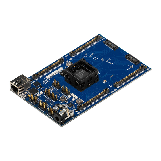
TriBoard TC3X7
TriBoard Manual TC3X7
Hardware: TriBoard TC3X7 TH V2.0( 1) and TriBoard TC3X7 V2.0
About this document
Scope and purpose
The User Manual provide information about using, configuration and connecting the TriBoard with Infineon
AURIX™ TC3X7 device. The manual provide information for different hardware types. There exist different
hardware with Through Hole socket (TriBoard TC3X7 TH) and soldered devices (TriBoard TC3X7). The schematic
is identically for the all boards if not other mentioned in chapter schematic. The placing on the boards is slightly
different around the TC3X7 itself dependent of the space (socket need more space and has through hole), but the
most components are on the same location. All figures are valid for each board if not differently mentioned.
Intended audience
Design, verfication, test and software engineers will use this document to get an understanding of the
functionality and connections of the TriBoard.
User Manual
www.infineon.com
Please read the Important Notice and Warnings at the end of this document
V2.1
2018-10
Advertisement
Table of Contents

Related Manuals for Infineon TriBoard TC3X7 Series


Summary of Contents for Infineon TriBoard TC3X7 Series
-
Page 1: About This Document
About this document Scope and purpose The User Manual provide information about using, configuration and connecting the TriBoard with Infineon AURIX™ TC3X7 device. The manual provide information for different hardware types. There exist different hardware with Through Hole socket (TriBoard TC3X7 TH) and soldered devices (TriBoard TC3X7). The schematic is identically for the all boards if not other mentioned in chapter schematic. -
Page 2: Table Of Contents
TriBoard Manual TC3X7 Hardware: TriBoard TC3X7 TH V2.0(1) and TriBoard TC3X7 V2.0 Table of Contents Table of Contents About this document ..............Preface-1 Table of Contents . -
Page 3: Table Of Contents
TriBoard Manual TC3X7 Hardware: TriBoard TC3X7 TH V2.0(1) and TriBoard TC3X7 V2.0 Table of Contents Config Signals ................5-2 Clock Signals . -
Page 4: Introduction
TriBoard Manual TC3X7 Hardware: TriBoard TC3X7 TH V2.0(1) and TriBoard TC3X7 V2.0 Introduction Introduction We congratulate you on your purchase of the TriCore Evaluation Board. This kit is a versatile tool, providing quick access to the capabilities of TriCore's powerful architecture. Applications can be developed easily. -
Page 5: Features
Hardware: TriBoard TC3X7 TH V2.0(1) and TriBoard TC3X7 V2.0 Features Features Summary of Features – Infineon’s TC3X7 (TC397, TC387, TC377) AURIX™ 2G Controller in LFBGA-292 Package – FlexRay™ Transceivers – High Speed CAN Transceivers (CAN-FD capable) – USB to UART bridge –... -
Page 6: Block Diagram
TriBoard Manual TC3X7 Hardware: TriBoard TC3X7 TH V2.0(1) and TriBoard TC3X7 V2.0 Features – 2K I2C Serial Eeprom with EUI-48™ Node Identity (MICROCHIP) – Reset switch – Enable switch – Generic switch – 4-pin Dip switch Zero Ohm Bridges Zero Ohm resistors give the flexibility to configure the systems functionality. Block Diagram XTAL CAN0... -
Page 7: Placement
TriBoard Manual TC3X7 Hardware: TriBoard TC3X7 TH V2.0(1) and TriBoard TC3X7 V2.0 Features Placement X306 X604 X601 X 202 S202 Y 401 D 302 D303 D304 D305 D306 D 307 D308 D309 X403 X201 U 401 X404 D401 D402 T301 X402 U 201 T 302... -
Page 8: Triboard Information
Please check always the latest manual for complete list of usable devices. Power Supply All needed voltages are generated via Infineon’s Multi Voltage Safety Micro Processor Supply TLF35584QV and via the microcontroller itself (+1,25V). The supply device is available as two different devices: TLF35584QVVS1 ->... -
Page 9: Leds
TriBoard Manual TC3X7 Hardware: TriBoard TC3X7 TH V2.0(1) and TriBoard TC3X7 V2.0 TriBoard Information X306 X604 X601 X202 C310 L301 S202 R390 R399 CB319 C311 C318 X404 R382 Y401 C309 CB318 R392 R393 R394 R 395 R396 R397 R398 R3104 R402 R439 X403... -
Page 10: Serial Connection To Pc
TriBoard Manual TC3X7 Hardware: TriBoard TC3X7 TH V2.0(1) and TriBoard TC3X7 V2.0 TriBoard Information 3.5.1 Serial Connection to PC After the first connection of USB to a PC the needed driver will be installed automatically. During this there will be created a new COM port on PC. This COM port can be used to communicate with the board via ASCLIN0 of the device. -
Page 11: Flexray™ (E-Ray)
TriBoard Manual TC3X7 Hardware: TriBoard TC3X7 TH V2.0(1) and TriBoard TC3X7 V2.0 TriBoard Information Per default the miniWiggler is connected to the DAP. It is possible to change the connection to DAPE (DAP of emulation device if available). If resistors R214, R215 and R216 assembled (default) then the standard DAP is connected to miniWiggler otherwise if R217, R218 and R219 are assembled the the DAPE of emulation device is connected to miniWiggler. -
Page 12: Ethernet
TriBoard Manual TC3X7 Hardware: TriBoard TC3X7 TH V2.0(1) and TriBoard TC3X7 V2.0 TriBoard Information 3.10 Ethernet The TriBoard provide a RJ45 connector (X306) for twisted pair ethernet connections.The TriBoard use a Realtek Integrated 10/100/1000M Ethernet Precision Transceiver RTL8211FI-CG as physical interface device. For more information about the ethernet modul see TC3X9 User’s Manual, about the PHY see the RTL8211F datasheet. -
Page 13: Adc
TriBoard Manual TC3X7 Hardware: TriBoard TC3X7 TH V2.0(1) and TriBoard TC3X7 V2.0 TriBoard Information C316 C315 C314 C317 X701 X704 R389 C308 C305 CB315 R260 R258 R3105 C312 CB312 C319 C313 C404 CB316 C406 CB314 C405 R370 CB409 R372 CB313 R414 R404 L402... - Page 14 TriBoard Manual TC3X7 Hardware: TriBoard TC3X7 TH V2.0(1) and TriBoard TC3X7 V2.0 TriBoard Information X306 X604 X601 X202 C310 L301 S202 R390 R399 CB319 C311 C318 X404 R382 Y401 C309 CB318 R392 R393 R394 R 395 R396 R397 R398 R3104 R402 R439 X403...
-
Page 15: Other Peripherals
TriBoard Manual TC3X7 Hardware: TriBoard TC3X7 TH V2.0(1) and TriBoard TC3X7 V2.0 TriBoard Information 3.13 Other peripherals For all other peripherals there are no special plugs on the board. The peripheral signals are available on the different connectors. See “Connector Pin Assignment” on Page 6-1. -
Page 16: Dap_Scr
TriBoard Manual TC3X7 Hardware: TriBoard TC3X7 TH V2.0(1) and TriBoard TC3X7 V2.0 TriBoard Information 3.16.4 DAP_SCR Additional DAP connector (X406) is connected to DAP_SCR. This DAP can be used as private DAP connection to the standby controller. For pinout of this connector see Figure 6-11. -
Page 17: Agbt (Optional)
TriBoard Manual TC3X7 Hardware: TriBoard TC3X7 TH V2.0(1) and TriBoard TC3X7 V2.0 TriBoard Information C316 C315 C314 C317 X701 X704 R389 C308 C305 CB315 R260 R258 R3105 C312 CB312 C319 C313 C404 CB316 C406 CB314 C405 R370 CB409 R372 CB313 R414 R404 L402... - Page 18 TriBoard Manual TC3X7 Hardware: TriBoard TC3X7 TH V2.0(1) and TriBoard TC3X7 V2.0 TriBoard Information The needed Samtec connector is the JST B4B-PH-K. The connector provide the input voltage to the Ethernet miniWiggler and an enable/wakeup signal connected to TLF35584 and a standby voltage of +1,25V connected to VDDSB of device. In case the EmW is used you must remove R522.
-
Page 19: Triboard Configuration
TriBoard Manual TC3X7 Hardware: TriBoard TC3X7 TH V2.0(1) and TriBoard TC3X7 V2.0 TriBoard Configuration TriBoard Configuration HW Boot Configuration Figure 4-1 HW Configuration DIP-Switches The picture above shows the definition of the boot HW configuration switch. The meaning of the switches will be described in the following table (Table 4-1). -
Page 20: Assembly Options
TriBoard Manual TC3X7 Hardware: TriBoard TC3X7 TH V2.0(1) and TriBoard TC3X7 V2.0 TriBoard Configuration Assembly Options 4.2.1 General optional resistors Table 4-2 General optional resistors (default assembly in brackets) Component Description R202 Connect P20.2 (/TESTMODE) to GND (not assembled) R203 XTAL1 Rload (50 Ohm) (not assembled) R206 XTAL Rparallel (not assembled) - Page 21 TriBoard Manual TC3X7 Hardware: TriBoard TC3X7 TH V2.0(1) and TriBoard TC3X7 V2.0 TriBoard Configuration X306 X604 X601 X202 C310 L301 S202 R390 R399 CB319 C311 C318 X404 R382 Y401 C309 CB318 R392 R393 R394 R 395 R396 R397 R398 R3104 R402 R439 X403...
-
Page 22: Resistors For Peripherals
TriBoard Manual TC3X7 Hardware: TriBoard TC3X7 TH V2.0(1) and TriBoard TC3X7 V2.0 TriBoard Configuration 4.2.2 Resistors for peripherals Table 4-3 Resistors for peripherals (default assembly in brackets) Component Description R220 Connect V_VR with VDDM (assembled) R221 Connect +3V3 with VDDM (not assembled) R222 Connect VAREF1 with VDDM (assembled) R223... - Page 23 TriBoard Manual TC3X7 Hardware: TriBoard TC3X7 TH V2.0(1) and TriBoard TC3X7 V2.0 TriBoard Configuration Table 4-3 Resistors for peripherals (default assembly in brackets) (continued) Component Description R374 Connect P11.6 with TXCTL of Ethernet PHY (assembled) R375 Connect P12.1 with MDIO of Ethernet PHY (assembled) R376 Connect P12.0 with MDC of Ethernet PHY (assembled) R377...
- Page 24 TriBoard Manual TC3X7 Hardware: TriBoard TC3X7 TH V2.0(1) and TriBoard TC3X7 V2.0 TriBoard Configuration C316 C315 C314 C317 X701 X704 R389 C308 C305 CB315 R260 R258 R3105 C312 CB312 C319 C313 C404 CB316 C406 CB314 C405 R370 CB409 R372 CB313 R414 R404 L402...
-
Page 25: Signal (On Board Used) Description
TriBoard Manual TC3X7 Hardware: TriBoard TC3X7 TH V2.0(1) and TriBoard TC3X7 V2.0 Signal (on board used) Description Signal (on board used) Description For more information about the signals please see the user manual/datasheet for TC3X7 and/or the schematics of the board. All not mentioned signals are not used on the board and can be used outside. -
Page 26: Config Signals
TriBoard Manual TC3X7 Hardware: TriBoard TC3X7 TH V2.0(1) and TriBoard TC3X7 V2.0 Signal (on board used) Description Config Signals Table 5-3 Config Signals Short name Description P14.5 HWCFG1 (EVR33OFF / EVR33ON) P14.2 HWCFG2 (EVRCOFF / EVRCON) P14.4 HWCFG6 (Pins in tristate / Pins with pull-up) P14.3 HWCFG3 (Boot from pins / Boot from Flash BMI) P10.5... -
Page 27: Peripheral Signals
TriBoard Manual TC3X7 Hardware: TriBoard TC3X7 TH V2.0(1) and TriBoard TC3X7 V2.0 Signal (on board used) Description Peripheral Signals Table 5-6 Peripheral Signals Short name Description P14.1 ASCLIN0 Receive Input A CAN01 Receive Input B (optional) P14.0 ASCLIN0 Transmit Output CAN01 Transmit Output (optional) P15.3 ASCLIN0 Receive Input B (optional) - Page 28 TriBoard Manual TC3X7 Hardware: TriBoard TC3X7 TH V2.0(1) and TriBoard TC3X7 V2.0 Signal (on board used) Description Table 5-6 Peripheral Signals (continued) Short name Description REFCLK Ethernet GREFCLK Input (P11.5) TCTL Ethernet TCTL Output (P11.6) RXD3 Ethernet RXD3 Input A (P11.7) RXD2 Ethernet RXD2 Input A (P11.8) RXD1...
-
Page 29: Connector Pin Assignment
TriBoard Manual TC3X7 Hardware: TriBoard TC3X7 TH V2.0(1) and TriBoard TC3X7 V2.0 Connector Pin Assignment Connector Pin Assignment The TriBoard will be shipped with four male (plug) connectors on top layer and four female (socket) connectors on bottom layer. The default connectors are 80-pol. Board to Board connectors from Samtec: http://www.samtec.com Plug: FTSH-140-02-L-DV-ES-A... -
Page 30: Tc3X7 Connector / Top View
TriBoard Manual TC3X7 Hardware: TriBoard TC3X7 TH V2.0(1) and TriBoard TC3X7 V2.0 Connector Pin Assignment TC3X7 Connector / Top View BUS EXPANSION (X601,X701) PERIPHERALS (X602,X702) P21.6 VCC_IN VCC_IN P21.7 VCC_IN VCC_IN 9 10 P22.4 9 10 P22.8 11 12 P22.5 11 12 P22.9 13 14... - Page 31 TriBoard Manual TC3X7 Hardware: TriBoard TC3X7 TH V2.0(1) and TriBoard TC3X7 V2.0 Connector Pin Assignment ADC (X603, X703) GTM / PORTS (X604,X704) AN16 P00.9 P11.14 AN17 P00.10 P11.15 9 10 AN18 P02.0 9 10 11 12 AN19 P02.1 11 12 13 14 AN20 P02.2...
-
Page 32: Power Connector Pinout
TriBoard Manual TC3X7 Hardware: TriBoard TC3X7 TH V2.0(1) and TriBoard TC3X7 V2.0 Connector Pin Assignment Power connector pinout +3,5V...40V Figure 6-3 Power connector pinout (Roka 520 2550 USB connector pinout Figure 6-4 USB connector pinout (Micro USB B-type) FlexRay™ (ERAY) connector pinout Figure 6-5 FlexRay™... -
Page 33: Lin Connector Pinout
TriBoard Manual TC3X7 Hardware: TriBoard TC3X7 TH V2.0(1) and TriBoard TC3X7 V2.0 Connector Pin Assignment LIN connector pinout Figure 6-7 LIN connector pinout (IDC10) HSCT connector pinout Figure 6-8 HSCT connector pinout (IEE1394 6-conductor) Ethernet connector pinout Figure 6-9 Ethernet connector pinout (RJ45) User Manual V2.1 TriBoard TC3X7 TH V2.0(1) and TriBoard TC3X7 V2.0... -
Page 34: Ocds1 Connector Pinout
TriBoard Manual TC3X7 Hardware: TriBoard TC3X7 TH V2.0(1) and TriBoard TC3X7 V2.0 Connector Pin Assignment 6.10 OCDS1 connector pinout Figure 6-10 OCDS1 connector pinout (IDC16) 6.11 DAP connector pinout Figure 6-11 DAP connector pinout (Samtec FTSH10) User Manual V2.1 TriBoard TC3X7 TH V2.0(1) and TriBoard TC3X7 V2.0 2018-10... -
Page 35: Etk Connector Pinout
TriBoard Manual TC3X7 Hardware: TriBoard TC3X7 TH V2.0(1) and TriBoard TC3X7 V2.0 Connector Pin Assignment 6.12 ETK connector pinout Figure 6-12 ETK connector pinout (Samtec TFM-105) 6.13 Ethernet miniWiggler power connector pinout Figure 6-13 Ethernet miniWiggler connector pinout (JST B4B-PH) User Manual V2.1 TriBoard TC3X7 TH V2.0(1) and TriBoard TC3X7 V2.0... -
Page 36: Agbt Connector Pinout
TriBoard Manual TC3X7 Hardware: TriBoard TC3X7 TH V2.0(1) and TriBoard TC3X7 V2.0 Connector Pin Assignment 6.14 AGBT connector pinout 1 0 1 2 1 4 1 6 1 8 2 0 2 2 G N D G N D 1 1 1 3 1 5 1 7 1 9 2 1 Figure 6-14 AGBT connector pinout (Samtec ASP-137969-01) User Manual... -
Page 37: Schematic And Layout
TriBoard Manual TC3X7 Hardware: TriBoard TC3X7 TH V2.0(1) and TriBoard TC3X7 V2.0 Schematic and Layout Schematic and Layout Known problems 7.1.1 Known problems on TriBoard TC3X7 TH V2.0(1) R386 is assembled via wire wrap on version V2.0. 7.1.2 Known problems on TriBoard TC3X7 V2.0 No problems known. - Page 38 TriBoard Manual TC3X7 Hardware: TriBoard TC3X7 TH V2.0(1) and TriBoard TC3X7 V2.0 Schematic and Layout Figure 7-1 Schematic - Project User Manual V2.1 TriBoard TC3X7 TH V2.0(1) and TriBoard TC3X7 V2.0 2018-10...
- Page 39 TriBoard Manual TC3X7 Hardware: TriBoard TC3X7 TH V2.0(1) and TriBoard TC3X7 V2.0 Schematic and Layout Figure 7-2 Schematic - Clock, Config, Debug, Ports and ADC User Manual V2.1 TriBoard TC3X7 TH V2.0(1) and TriBoard TC3X7 V2.0 2018-10...
- Page 40 TriBoard Manual TC3X7 Hardware: TriBoard TC3X7 TH V2.0(1) and TriBoard TC3X7 V2.0 Schematic and Layout Figure 7-3 Schematic - On Board Peripherals User Manual V2.1 TriBoard TC3X7 TH V2.0(1) and TriBoard TC3X7 V2.0 2018-10...
- Page 41 TriBoard Manual TC3X7 Hardware: TriBoard TC3X7 TH V2.0(1) and TriBoard TC3X7 V2.0 Schematic and Layout Figure 7-4 Schematic - miniWiggler JDS and Debug connectors User Manual V2.1 TriBoard TC3X7 TH V2.0(1) and TriBoard TC3X7 V2.0 2018-10...
- Page 42 TriBoard Manual TC3X7 Hardware: TriBoard TC3X7 TH V2.0(1) and TriBoard TC3X7 V2.0 Schematic and Layout Figure 7-5 Schematic - Power Supply User Manual V2.1 TriBoard TC3X7 TH V2.0(1) and TriBoard TC3X7 V2.0 2018-10...
- Page 43 TriBoard Manual TC3X7 Hardware: TriBoard TC3X7 TH V2.0(1) and TriBoard TC3X7 V2.0 Schematic and Layout Figure 7-6 Schematic - Connectors (Plug) User Manual V2.1 TriBoard TC3X7 TH V2.0(1) and TriBoard TC3X7 V2.0 2018-10...
- Page 44 TriBoard Manual TC3X7 Hardware: TriBoard TC3X7 TH V2.0(1) and TriBoard TC3X7 V2.0 Schematic and Layout Figure 7-7 Schematic - Connectors (Socket) User Manual V2.1 TriBoard TC3X7 TH V2.0(1) and TriBoard TC3X7 V2.0 2018-10...
-
Page 45: Layout
TriBoard Manual TC3X7 Hardware: TriBoard TC3X7 TH V2.0(1) and TriBoard TC3X7 V2.0 Schematic and Layout Layout Figure 7-8 Component Plot Top Layer User Manual V2.1 TriBoard TC3X7 TH V2.0(1) and TriBoard TC3X7 V2.0 2018-10... - Page 46 TriBoard Manual TC3X7 Hardware: TriBoard TC3X7 TH V2.0(1) and TriBoard TC3X7 V2.0 Schematic and Layout Figure 7-9 Component Plot Bottom Layer User Manual 7-10 V2.1 TriBoard TC3X7 TH V2.0(1) and TriBoard TC3X7 V2.0 2018-10...
-
Page 47: Layout With Dimensioning
TriBoard Manual TC3X7 Hardware: TriBoard TC3X7 TH V2.0(1) and TriBoard TC3X7 V2.0 Schematic and Layout Layout with Dimensioning The following dimensions should be used for development of extension boards. Figure 7-10 Dimensioning (mm) User Manual 7-11 V2.1 TriBoard TC3X7 TH V2.0(1) and TriBoard TC3X7 V2.0 2018-10... - Page 48 TriBoard Manual TC3X7 Hardware: TriBoard TC3X7 TH V2.0(1) and TriBoard TC3X7 V2.0 Schematic and Layout Figure 7-11 Dimensioning (mil) The dimensioning is valid for all TriBoards. User Manual 7-12 V2.1 TriBoard TC3X7 TH V2.0(1) and TriBoard TC3X7 V2.0 2018-10...
- Page 49 TriBoard Manual TC3X7 Hardware: TriBoard TC3X7 TH V2.0(1) and TriBoard TC3X7 V2.0 Revision History Page or Item Subjects (major changes since previous revision) V2.1, 2018-10 add TC377 as usable device and adapt description for TC377 User Manual RevisionHistory-1 V2.1 TriBoard TC3X7 TH V2.0(1) and TriBoard TC3X7 V2.0 2018-10...
- Page 50 Infineon Technologies, Infineon Technologies in customer's applications. Document reference Infineon Technologies’ products may not be used in The data contained in this document is exclusively Doc_Number any applications where a failure of the product or any intended for technically trained staff.
Need help?
Do you have a question about the TriBoard TC3X7 Series and is the answer not in the manual?
Questions and answers