Table of Contents
Advertisement
Quick Links
Advertisement
Table of Contents

Subscribe to Our Youtube Channel
Related Manuals for Shini SG-24


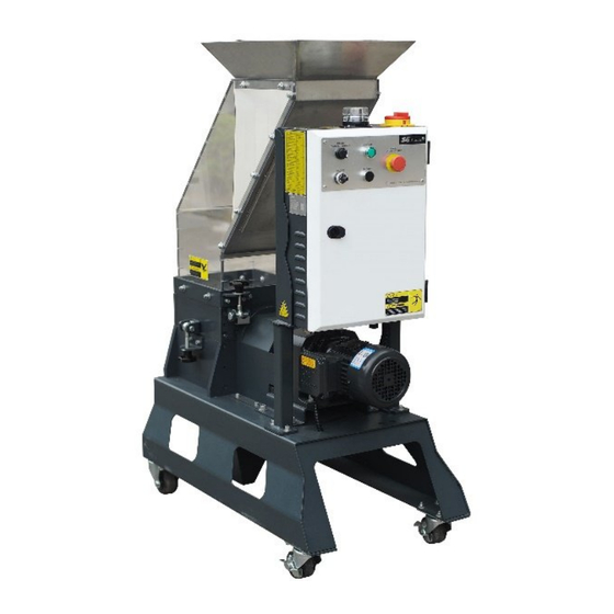
Summary of Contents for Shini SG-24
- Page 1 SG-24 Screenless Granulators Date: Nov. 2023 Version: Ver.A (English)
-
Page 2: Table Of Contents
Contents General Description ................... 6 1.1 Coding Principle ..................7 1.2 Feature ....................7 1.3 Safety Regulations ................9 1.3.1 Safety Signs and Labels ............. 9 1.3.2 Transportation and Storage of the Machine ......10 1.4 Exemption Clause ................11 Structural Features and Working Principle .......... - Page 3 4.3 Open the Feed Box and Storage Bin ..........23 4.3.1 Open the Feed Box ..............23 4.3.2 Open the Storage Bin ............... 24 4.4 Shut the Feed Box and Storage Bin ............ 24 4.4.1 Shut the Feed Box ..............24 4.4.2 Shut the Storage Bin ..............
- Page 4 6.8.3 Monthly Check ................42 6.9 Cleaning ....................42 6.10 Maintenance Schedule ............... 43 6.10.1 About the Machine..............43 6.10.2 Check after Installation ............. 43 6.10.3 Daily Check ................43 6.10.4 Weekly Check ................44 6.10.5 Monthly Check ................44 6.10.6 Check Half-yearly or Every 1000 Running Hours .....
- Page 5 Picture 6-4: Dismantle Rotate Blades ..............33 Picture 6-5: Installation of Bearing and Cutter Shaft 1 ........34 Picture 6-6: Installation of Bearing and Cutter Shaft 2 ........34 Picture 6-7: Installation of Bearing and Cutter Shaft 3 ........35 Picture 6-8: Installation of Teeth Cutter and Fixed Blade ........
-
Page 6: General Description
1. General Description Please read this manual carefully before using this machine in order to operate correctly against any damage caused due to improper operation. Note! Always take great care when the knives are within reach, they are very sharp and can cause personal injury. -
Page 7: Coding Principle
1) Adopting gear box of global brand, SG-24 series features steady performance, long service life and large transfer torque. 2) SG-24 series teeth cutters and cutting blades are integrally fitted in one cutting chamber. Screenless design, well-proportioned size of regrinds and least amount of dusts. - Page 8 Chapter 6, which contains service instructions intended for service engineers. Other chapters contain instructions for the daily operator. Any modifications of the machine must be approved by SHINI in order to avoid personal injury and damage to machine. We shall not be liable for any damage caused by unauthorized change of the machine.
-
Page 9: Safety Regulations
Safety Regulations Follow the instructions in this manual to avoid personal injury and damage to machine components. 1.3.1 Safety Signs and Labels Electrical installation must only be done by a competent electrician! Before the granulator is opened for servicing and maintenance, always disconnect the power with both the main switch and the control switch on the granulator. -
Page 10: Transportation And Storage Of The Machine
25℃ to +55℃ for long distance transportation and for a short distance, it can be transported with temperature under +70℃. Storage 1) SG-24 series should be stored indoors with temperature kept from 5℃ to 40℃ and humidity below 80%. 2) Disconnect all power supply and turn off main switch and exigency stop switch. -
Page 11: Exemption Clause
1) Indoors in a dry environment with max. temperature +45℃ and humidity no more than 80%. Do not use the machine: 1) If it is with a damaged cord. 2) On a wet floor or when it is exposed to rain to avoid electric shock. 3) If it has been dropped or damaged until it is checked or fixed by a qualified serviceman. - Page 12 The following statements clarify the responsibilities and regulations born by any buyer or user who purchases products and accessories from Shini (including employees and agents). Shini is exempted from liability for any costs, fees, claims and losses caused by reasons below: 1) Any careless or man-made installations, operation and maintenances upon machines without referring to the Manual prior to machine using.
-
Page 13: Structural Features And Working Principle
2. Structural Features and Working Principle General Description SG-24 series screenless granulators, which mainly works with the injection molding machine to crush a small amout of material. When crushing, don’t input excessive materials. The granulator are controlled by main power switch, emergency stop button, start button, stop button and safety switches. -
Page 14: Safety System
In case the safety system of granulator is changed, our company will not perform our commitment. The replacement of all spare parts will be done by SHINI Company. -
Page 15: Gate Lock
Picture 2-3: Safety Switch 2.2.3 Gate Lock For opening feed box and cutting chamber, users need to loosen a long star screw (gate lock). It takes some time to unscrew the lock to completely stop cutter shaft and avoid personal injuries. Notice before startup: 1) Check if feed box is tightened. -
Page 16: Options
1) Transformer, provide suitable voltage for control circuit. 2) Microcomputer control board (PCB) achieves granulator normal operation, material blockage reverse running and related alarm function. 3) Fuse, perform the function of overload and short phase protection. 4) Circuit breaker, isolate or short circuit protection. 5) Contactor, connect or disconnect circuit in a distance. -
Page 17: Cutters
2.4.3 Cutters On the basis of standard cutter, additional wide cutters or narrow cutter are provided for options. Picture 2-7: Cutter Size 2.4.4 30-second Instant Recycling System-VR Type The 30-sec. instant recycling system utilizes the high-pressure blower to blow the regrinds in the material storage tank to the proportional mixer and reuse the regrinds after mixing, so that the sprues will not have physical properties and color changes due to oxidation and humidification, thus improving the products quality. - Page 18 regrinds in the material storage tank to the proportional mixer and reuse the regrinds after mixing, so that the sprues will not have physical properties and color changes due to oxidation and humidification, thus improving the products quality. 1. Vacuum Loader 2.
-
Page 19: Installation And Debugging
3. Installation and Debugging Read through this chapter before installation. Must abide by the following installation steps to avoid personnel injuries or damage of the machine! Take great care of handing the blades because they are very sharp and may cause cutting injuries! Power supply of the machine should be handled by qualified electricians! Be careful! Cutting blades must be put balanced, prevent it to rotate itself when do the... -
Page 20: Picture 3-1: Installation Notice
4) The power cable connection terminals should be tightened securely. 5) The machine requires a 3-phase 4-wire power source, connect the power lead (L1, L2, L3) to the live wires, and the earth (PE) to the ground. 6) Power supply requirements: Main power voltage: +/- 5% Main power frequency: +/- 2% 7) Make at least 1 meter clearance around the machine to facilitate repair... -
Page 21: Installation Place
3.1 Installation Place Check and make sure the installation ground is level.There is enough intensity when it is running, and lockup the castors. Picture 3-2: Installation Place 21(44) -
Page 22: Operation Guide
1) Check if blades are damaged and loose. 2) Check if rotor is damaged and loose. Please contact Shini Company if any situation above has been found. Startup Pretest Unpainted part of the machine has been covered with antirust oil. Before use, the antirust oil should be cleaned. -
Page 23: Circuit Connection
4.2 Circuit Connection Note: The installation of the granulator's circuit must be conducted by the professional electricians. 1) Check if feed box is fully closed; 2) Check if storage bin is fully closed; 3) Ensure the main power switch is in ON position. 4) Check if emergency stop is under action;... -
Page 24: Open The Storage Bin
Picture 4-1: Open the Feed Box 4.3.2 Open the Storage Bin 1) Turn off granulator power. 2) Loosen long star screw. 3) Pull out storage bin. Shut the Feed Box and Storage Bin 4.4.1 Shut the Feed Box Note: Please take care when closing the feed box! Note: Make sure feed box is fully closed, otherwise machine would not start. -
Page 25: Motor Reversed Protective Function
The granulator is controlled by main power switch, safety switch, START/STOP button and emergency stop button. Main power switch is located at the front control panel. And the startup and stop of the machine is controlled through rotating the main poewer switch. Picture 4-2: Main Power Switch START button and STOP button: These two buttons control the startup and stop of the machine. -
Page 26: Picture 4-4: Motor Reversed Protection
When there are hard material appear in the feed box and cutting chamber or for other reason the cutting blades can not cut, this unit will enable blade shaft reverse rotating with alarm, it resumes normal operation automatically after 3 seconds later, so to keep granulating material. -
Page 27: Guidance
Guidance 27(44) -
Page 28: Operation Flow
Operation Flow Count backward time M+6S F-14 F-11 F-21 F-24 Parameter:on Parameter: Parameter:ID Parameter:check Reverse function countdown time Range:1~99 Range: Range:On, Off Default value:1 Range:0: None Default value:On 00:00~99:59 1:odd 2:Even Default value: Default value: 00:00(off) None F-12 F-22 F-25 Parameter:off Parameter:Baud Parameter:stop... -
Page 29: Motor Detection Logic
Motor Detection Logic Note: There is 1S switching time between forward and reverse rotation. When the Sensor input signal is less than 4 (including 4) pulse signals, it is judged that the motor is stuck. When the Sensor input signal is greater than 4 (including 4) pulse signals, it is judged that the motor is not stuck. -
Page 30: Intermittent Running
2) When there is an alarm, the fault Relay outputs, while the NC Relay can’t output. 3) 3) When there is no alarm, the fault Relay can’t output, and the NC Relay outputs. 4.10.2 Intermittent running 1) When the timing switch signal is input and the F-11 and F12 parameters are not 00:00, the countdown timer will run intermittently. -
Page 31: Trouble-Shooting
5. Trouble-shooting Granulator Can Not Work 1) Check if the emergency stop has been reset or not. If not, rotate the button anti-clockwise to reset it. 2) Check if the safety switch between feed box and storage box is completely closed. If not, machine can not be started. 3) Checking overload protector of the motor. -
Page 32: Maintenance And Repair
6. Maintenance and Repair Picture 6-1: Maintenance and Repair 1) Check whether emergency stop works normally. Period: daily. 2) Check whether START/STOP button works normally. Period: daily. 3) Check whether main power switch works normally. Period: daily. 4) Check whether material stopper is intact before startup. Period: daily. 5) Check whether star screws in feed box and storage bin are tightened. -
Page 33: Picture 6-2: Blades Maintenance
Picture 6-2: Blades Maintenance Note: To decrease the possibility of harm to other people, the replacement action must be conducted by oneself. 1. Remove the fixed blades Note: To avoid self rotation, block the rotating blade with a thick wood block. Note: Be careful with the sharp blades. -
Page 34: Installation Of Bearing And Cutter Shaft
3. Install the blades Clean carefully the fixed blades and rotating blades and then install them. 1) Install the rotating blades 2) Then the fixed blades 3) Finally the front fixed blades Note: Each time to replace the blade, the screw and insulation ring must be replaced also. -
Page 35: Installation Of Feed Box, Feed Port And Storage Bin
4) Fix the bearing base on the cutting chamber. Picture 6-7: Installation of Bearing and Cutter Shaft 3 Note: Daub the lubrication on the bearing and bearing base. Use proper twisting force to lock the screw tightly. 5) Use a wrench to tight up all the screws on bearing block or cutting chamber and lock them up with right torque (M12×25). - Page 36 Picture 6-9: Installation of Feed Box, Feed Port and Storage Bin 1 2) Put the feed box on the cutting chamber, insert the rotation shaft of feed box (BH10184900010) into the hole, and then use the inner hexagon screw (M8×20) to lock up both ends. Picture 6-10: Installation of Feed Box, Feed Port and Storage Bin 2 3) Hold the storage bin with both hands and push it into its right position along the slide way.
-
Page 37: Cutting Chamber Disassembly
Picture 6-12: Installation of Feed Box, Feed Port and Storage Box 4 Note: Lock nut is necessary for keeping screws falling into cutting chamber. Cutting Chamber Disassembly 6.4.1 Gear box dismantlement 1) Dismantle the screw of gear box’s fixed plate to push out the gear box directly outward to separate the coupler;... -
Page 38: Bearing Dismantlement
Picture 6-15: Step 2 of Left / Right Bearing Base Dismantlement 3) Dismantle the left bearing base, and then the left and right bearing bases are taken out. Picture 6-16: Step 3 of Left/ Right Bearing Base Dismantlement 6.4.3 Bearing Dismantlement 1) Put the fitted iron rod on the shaft sleeve, and use the copper stick to knock the top of the iron rod, then shaft sleeve is taken down. -
Page 39: Installation Of Reduction Gear
Picture 6-19:Step 3 of Bearing Dismantlement Installation of Reduction Gear Note: To stop blade rest shaft rotating while installation, use a thick wood block to stuck rotate blades! 1) Firstly, fix the gear box on the fixed plate, and use the hexagonal screw to fasten. -
Page 40: Transmission
3) Install the sensor fixed plate M6×12. Shaft coupler Sensor Picture 6-22: Installation of Reduction Gear 3 Note: The cutting blade rest shall be put stably and avoid cutter self-rotation.At the time of operating, hand shall stay away from the cutting tool to avoid bodily injury. Transmission 6.6.1 Maintenance of Reduction Gear Replace lubricating oil after initial motor running for 400 hours, and oil change... -
Page 41: Maintenance
Check the lubricating oil level and install oil level plug. 3) Lubricating oil replacement: Increased viscosity of the lubricating oil will make it harder to discharge the oil, so better replace it when the motor is in its operational temp. Cut power off so to avoid electric shock. -
Page 42: Weekly Check
stop working so to protect the machine. The thread length of the safety screw is 60 mm, damaged screw needs to be replaced by a new one. Picture 6-23: Star Screws 6.8.2 Weekly Check 1) Check the power wire to see whether there is any damage. If so, replace it immediately. -
Page 43: Maintenance Schedule
Picture 6-24: Machine Cleaning Note: Finish step 9 for every time of machine cleaning and also it at least has to be done for one time after 300 hours in operation. 6.10 Maintenance Schedule 6.10.1 About the Machine Model Manufacture date Ф... -
Page 44: Weekly Check
Check material check plate (strip) is perfect or not. Check whether emergency stop and safety switch works normally. Clean cutting chamber and feeding hopper. Check whether start, stop and power switches are normal. 6.10.4 Weekly Check Check all the electrical cables. Check if there are loose connections of electrical components.
Need help?
Do you have a question about the SG-24 and is the answer not in the manual?
Questions and answers