Table of Contents
Advertisement
Advertisement
Table of Contents

Related Manuals for Shini SCM Series


Summary of Contents for Shini SCM Series
- Page 1 Volumetric Doser Date: Apr. 2019 Version: Ver.G (English)
-
Page 3: Table Of Contents
Contents General Description ..................7 1.1 Coding Principle ..................8 1.2 Features ....................8 1.3 Accessory option ..................9 1.4 Machine Specifications ................. 10 1.4.1 Dimensions of Doser ..............10 1.4.2 Specification List ................. 11 1.5 Safety Regulations ................13 1.5.1 Safety Signs and Labels ............. - Page 4 Operation..................... 31 4.1 Control Panel (SCM) ................31 4.2 Start/Stop of the Machine ..............31 4.3 Operation Instruction ................32 4.3.1 IMM Mode Setting ............... 32 4.3.2 Extruder Mode ................35 4.3.3 Other Function Setting ..............36 4.3.4 Other Parameters Function ............37 4.4 Replace Dosing Screws ................
- Page 5 Picture 2-2: Electrical Descriptions 1 ..............22 Picture 2-3: Electrical Descriptions 2(Injection Mode)........23 Picture 2-4: Electrical Descriptions 3(Extrusion Mode) ........24 Picture 2-5: Electrical Components Layout ............25 Picture 2-6: Main Hopper .................. 27 Picture 2-7: Mixing System ................27 Picture 2-8: Heavy Base ...................
- Page 6 6(42)
-
Page 7: General Description
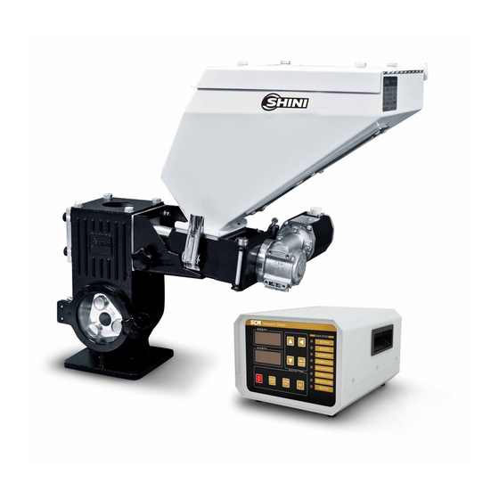
Please read this manual carefully before installation and using of the machine to prevent damage or personal injury. The SCM series volumetric dosers are suitable for auto-proportional mixing of new materials, regrinds, master batch and additives. A gear motor with deceleration ratio of 38:1 is coupled to a dosing screw of 12, 16, 20, and 30mm diameter to offer ten models with different output ranging from 0.1 to 110kg/hr to... -
Page 8: Coding Principle
D=Double Color Dosers 4=Four Color Dosers H=High temperature doser L=Screw of large output Shini Volumetric Doser 1.2 Features ● Dosing screws are chrome plated for durability. ● Unit is comprised of standard modules for ease of cleaning, disassembly and interchangeability. -
Page 9: Accessory Option
Chapter 6, which contains service instructions intended for service engineers. Other chapters contain instructions for the daily operator. Any modifications of the machine must be approved by SHINI in order to avoid personal injury and damage to machine. We shall not be liable for any damage caused by unauthorized change of the machine. -
Page 10: Machine Specifications
1.4 Machine Specifications 1.4.1 Dimensions of Doser Single Color Doser Double Color Doser High Temp.Doser Controller Picture 1-1: Dimensions of Doser 10(42) -
Page 11: Specification List
1.4.2 Specification List Table 1-1: Specification List 1 Single Color Unit Double Color Unit Model SCM-12 SCM-16 SCM-20 SCM-30 SCM-D Ver. Motor Power (kW) 0.06 0.06 0.06 0.06 0.06 × 2 (50/60Hz) Output Power of Mixer 0.09 0.09 0.09 0.09 0.09 ×... - Page 12 Table 1-2: Specification List 2 Model SCM-H-12 SCM-H-16 Ver. Motor Power (kW 50/60Hz) 0.06x2 0.06 Screw External Dia. (mm) Output Capacity (kg/hr) 0.5~8 1.0~32 Storage Hopper (L) Gear Ratio 38:1 38:1 Main Material Hopper(L) Optional (15) Optional (15) Mixer Optional Optional Floor Stand Optional...
-
Page 13: Safety Regulations
1.5 Safety Regulations Strictly abide by the following safety guide to prevent damage of the machine or personal injuries. 1.5.1 Safety Signs and Labels All the electrical components should be installed by qualified electricians. Turn off the main switch and control switch during maintenance or repair. Warning! High voltage! This sign is attached on the cover of control box! Warning! Be careful! -
Page 14: Exemption Clause
Shini (including employees and agents). Shini is exempted from liability for any costs, fees, claims and losses caused by reasons below: 1. Any careless or man-made installations, operation and maintenances upon machines without referring to the Manual prior to machine using. -
Page 15: Structure Characteristics And Working Principle
2. Structure Characteristics and Working Principle 2.1 Working Principle Picture 2-1: Working Principle Signals from control cabinet will be sent to motor. Then motor begins to work. The rotary force is transferred to the dosing screw through shaft connector. Color additives in hopper will fall into the groove of conveying screw then be taken to hopper base by rotating action of the screw to achieve accurately meter and convey master batch. -
Page 16: Assembly Drawing And Parts List
2.2 Assembly Drawing and Parts List 2.2.1 Assembly Drawing of Single-color Doser Note: Please refer to material List 2.2.2 for specific explanation of the Arabic numbers in parts drawing. Picture 2-3: Assembly Drawing of Single-color Doser 16(42) -
Page 17: Parts List Of Single-Color Doser
2.2.2 Parts List of Single-color Doser Table 2-1: Parts List of Single-color Doser Name Part NO. Name Part NO. Material keeping rubber Star handle B M8×35 YR40084500000 YR10002600000 (for screw 12) Material keeping rubber Flat gasket 8 YW66081900000 YR10003600000 (for screw 16, 20) Material keeping rubber Hexagon nut M8 YW64000800100... -
Page 18: Assembly Drawing Of Double Color Doser
2.2.3 Assembly Drawing of Double Color Doser Notes: Please refer to material List 2.2.4 for specific explanation of the Arabic numbers in parts drawing. Picture 2-3: Assembly Drawing of Double Color Doser 18(42) -
Page 19: Parts List Of Double Color Doser
2.2.4 Parts List of Double Color Doser Table 2-2: Parts List of Double Color Doser Name Part NO. Name Part NO. Star handle B M8×50 YR40084500000 Material fender 1 Flat gasket 8 YW66081900000 Material fender 2 Hexagon nut M8 YW64000800100 Side fixed frame Base door BW20387500210... -
Page 20: Assembly Drawing Of High Temp. Doser
2.2.5 Assembly Drawing of High Temp. Doser Notes: Please refer to material List 2.2.6 for specific explanation of the Arabic numbers in parts drawing. Picture 2-3: Assembly Drawing of High Temp. Doser 20(42) -
Page 21: Parts List Of High Temp. Doser
2.2.6 Parts List of High Temp. Doser Table 2-3: Parts List of High Temp. Doser Part NO. Part NO. Name Name Filter screen Motor fixing pin BH11003800610 Base Gear motor YM50652500000 End plate of doser BR90500200010 Material keeping rubber Manual tighten up Water pipe quick connector YW69616100000 YW59003800600... -
Page 22: Electrical Circuit Descriptions
2.3 Electrical Circuit Descriptions 2.3.1 Electrical Descriptions Picture 2-2: Electrical Descriptions 1 22(42) -
Page 23: Picture 2-3: Electrical Descriptions 2(Injection Mode)
Picture 2-3: Electrical Descriptions 2(Injection Mode) 23(42) -
Page 24: Picture 2-4: Electrical Descriptions 3(Extrusion Mode)
Picture 2-4: Electrical Descriptions 3(Extrusion Mode) 24(42) -
Page 25: Electrical Components Layout
2.3.2 Electrical Components Layout Picture 2-5: Electrical Components Layout 25(42) -
Page 26: Electrical Components List
2.3.3 Electrical Components List Table 2-4: Electrical Components List 26(42) -
Page 27: Optional Accessories
2.4 Optional Accessories 2.4.1 Main hopper The main material hopper is optional for both single and double color doser basing on customer demand. Picture 2-6: Main Hopper 2.4.2 Mixing System The mixing system is optional for both single and double color doser basing on customer demand. -
Page 28: Heavy Base
2.4.3 Heavy base When customer requires SHD-100~300kg or SHD-16OU~450U dryer, this heavy base is necessary. Picture 2-8: Heavy Base 28(42) -
Page 29: Installation And Debugging
Installation and Debugging Read this chapter carefully before installation. Install the machine by following steps. This series of models only could be applied in working environment with good ventilation. Power supply of the machine should be done by qualified electricians! 3.1 Install on Extrusion or Injection Molding Machine Picture 3-1: Installation of Single Color Doser Picture 3-2: Installation of Double Color Doser... -
Page 30: Power Supply Wiring
3.2 Power Supply Wiring Please select correct voltage and adjust the controller power to corresponding voltage before the Doser operation. 30(42) -
Page 31: Operation
Operation 4.1 Control Panel (SCM) Picture 4-1: Control Panel 1. Setting key 2. Up key 3. Down key 4. Switch 5. Menu key Chinese/English selection: Power on the machine, press the setting key for 3 secs. to switch English/Chinese. 4.2 Start/Stop of the Machine 1) Check whether the power is turned on. -
Page 32: Operation Instruction
4.3 Operation Instruction Three states of machine. The indicator has three states: Yellow: Standby Green:Run Red:Alarm 4.3.1 IMM Mode Setting According to circuit diagram (J1 connects pin 1-2), when connection is in IMM mode (it receives IMM 24VDC melt signal), the machine is at IMM mode after power on. - Page 33 2) Hold on the Setting key for 5 secs, and it enters the screen displaying manual feeding of screw 1. 3) Press Menu key to start feeding of screw No.1 4) Press Setting key , it enters screw 1 50 secs. output testing screen 5) Press Menu key to test screw 1 50 secs.
- Page 34 2. IMM Melting Time Setting 1) Press Menu key till it displays melting time setting screen as below: 2) Press setting key to shift the digital. Adjust the number by key. Set melting time, its default is 10 secs. 3) Press Menu key , save the setting and exit.
-
Page 35: Extruder Mode
4. Weight per Mould Setting Press menu key till it displays weight per mould screen. Input the product actual weight, and the default is 100g. After above settings, turn on the main switch . The machine will feed the masterbatch and additives in time according to IMM’s melting signal. Note: In this step, the input weight unit is consistent with that of the 50S measured value. -
Page 36: Other Function Setting
1) Press Menu key till it displays extruder max. output setting screen as below: Set hourly max. output during extruder operation. The default is 50Kg/H. 2) Press menu key , save the setting and exit. After above settings, turn on the main switch . -
Page 37: Other Parameters Function
required amount plus regrind required amount. The default is 0. 3. Screw 2 Optional Level Switch Mode Function: When hopper of screw 2 options with level switch that detects the low level during operation, screw 2 will stop metering. Insufficient regrinds will be fed by basterbatch and material proportionally and automatically. - Page 38 2. Motor Failure Alarm Setting: Note: Meting motor alarm method: L: level alarm, H: high level alarm. Motor used by company is low level alarm, the default is L. 3. Setting for Communication with Upper Unit After it enters above start screen, hold on together for 3 secs.
- Page 39 F26: Station No. 1~99 0:4800 F27:Baud Rate 1:9600 2:19200 3:38400 0:No F28:Odd-even Check 1:Even 2:Odd 1:1bit F29:Stop Bit 2:2bit 4. Metering Motor Output Note: For single ingredient, the metering motor outputs 1; For double ingredients, the metering motor outputs 2. 39(42)
-
Page 40: Replace Dosing Screws
4.4 Replace Dosing Screws 1) Cut off power supply, loosen snap hook of the hopper, draw out the hopper and screw. Then unlock the screw fastening plate to remove the conveying screw for replacement. During screw replacement, it should replace the sleeve simultaneously (different screw diameters are matching different sleeves). -
Page 41: Trouble Shooting
Trouble Shooting Failures Possible reasons Solutions 1. Power supply not connected. 1. Connect the power supply. No indicates on the 2. Fuse burnt out or control control cabinet. 2. Replace the fuse or check control board. board problems 1. Parameter mistakes. 1. -
Page 42: Maintenance And Repair
Maintenance and Repair 6.1 Repair All the repair work should be done by qualified technicians to prevent personal injuries and damage of the machine. 6.2 Maintenance Keep the surface of machine clean. 6.3 Maintenance Schedule 6.3.1 About the Machine Model Manufaturing date : Voltage Ф...
Need help?
Do you have a question about the SCM Series and is the answer not in the manual?
Questions and answers