
Subscribe to Our Youtube Channel
Related Manuals for Shini SG-36 Series


Summary of Contents for Shini SG-36 Series
- Page 1 SG-36 series Sound-proof Central Granulators Date: Oct, 2018 Version: Ver.B (English)
-
Page 3: Table Of Contents
Contents General Description ..................7 1.1 Coding Principle ..................8 1.2 Feature ....................8 1.3 Technical Specifications ................ 10 1.4 Safety Regulations ................12 1.4.1 Safety signs and labels ............... 12 1.4.2 Transportation and Storage of the Machine ........ 14 1.5 Exemption Clause ................. - Page 4 3.3 Options Installation ................27 3.3.1 The Dust Separate System Installation ........27 3.3.2 Conveying Belt Installation ............27 Operation Guide ..................28 4.1 Startup Pretest ..................28 4.1.1 Before the First Startup ............... 28 4.1.2 After First Startup for 2 Hours ............. 29 4.1.3 After First Startup for 20~30 Hours ..........
- Page 5 6.7.1 Lubricating oils ................48 6.7.2 Please grease the bearing with lubricating oils periodically ..48 6.8 Cleaning ....................49 6.9 Maintenance Schedule ................51 6.9.1 About the Machine ..............51 6.9.2 Check after Installation ............... 51 6.9.3 Daily Check ................51 6.9.4 Weekly Check ................
- Page 6 Picture 4-4: Close The Screen Bracket,Storage Box and Feeding Hopper..31 Picture 6-1: Remove The Rotating Blades ............36 Picture 6-2: Blades Installation Adjusting ............37 Picture 6-3: Installation of Rotating and Fixed Blade ........38 Picture 6-4: Installation of Bearing and Blade Rest .......... 40 Picture 6-5: Installation of Belt Pulley and Motor 1 (SG-3650) ......
-
Page 7: General Description
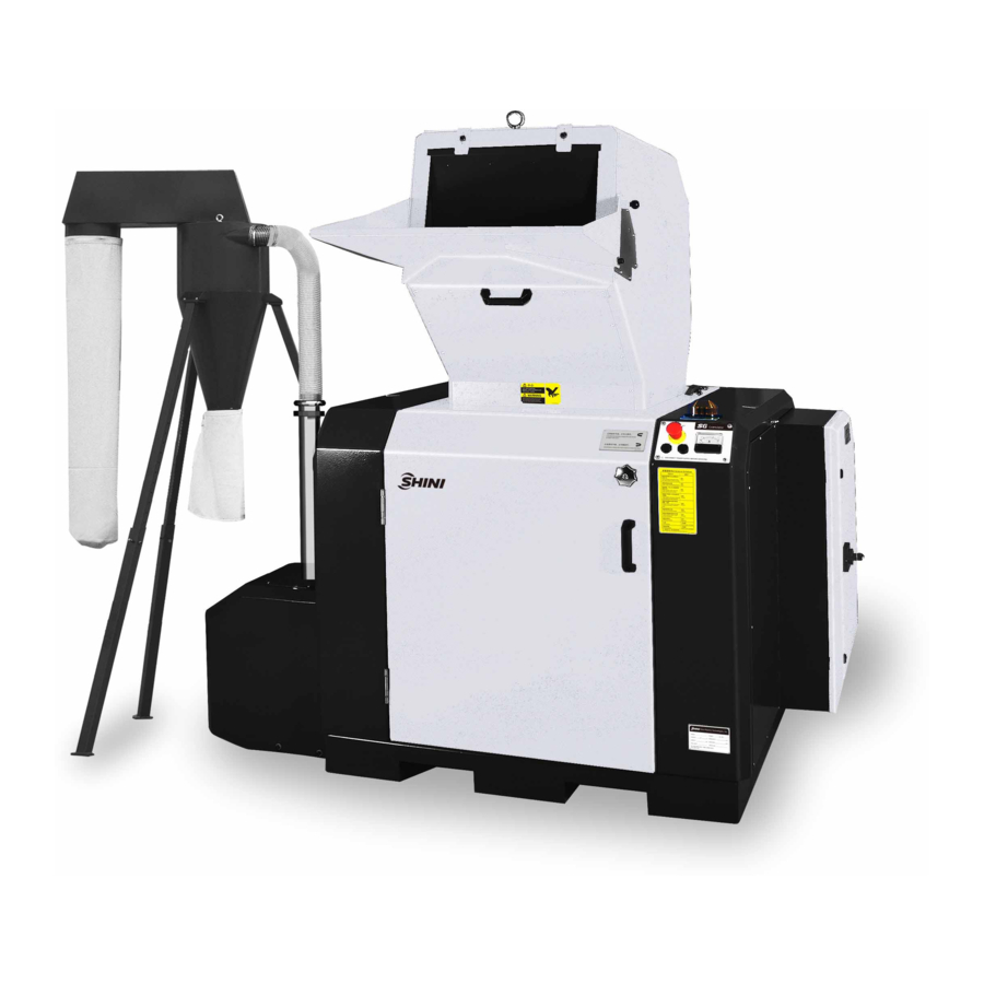
Forbidden to process flammable or toxic material! SG-36 series sound-proof central granulators are suitable for centralized recycling of wastes or rejected parts from injection moulding, blow moulding or extrusion lines. The machines feature optimized structure, easy operation, and quick blade replacement. -
Page 8: Coding Principle
1.1 Coding Principle 1.2 Feature l Adopts paddle blades. It allows increased efficiency and reduced energy consumption. l Blades adopt imported steel to ensure high quality and high durability. l Full-closed design and sound-proofing ensure low noise level. l Equipped with electrical current relay, motor overload protector and multiple safety devices. - Page 9 Any modifications of the machine must be approved by SHINI in order to avoid personal injury and damage to machine. We shall not be liable for any damage caused by unauthorized change of the machine. Our company provides excellent after-sales service. Should you have any problem during using the machine, please contact the company or the local vendor.
-
Page 10: Technical Specifications
1.3 Technical Specifications With belt conveyor Picture 1-1: Dimensions Chart 1-1: Technical Specifications Model SG-3650 SG-3675 Ver. Motor Power (kW, 50 / 60Hz) 18.5 Rotor Speed (r.p.m. 50 / 60Hz) 540/650 540/650 Conveying Blower (kW, 50 / 60Hz) 1.1/1.3 1.5/1.9 SKD11 SKD11 Teeth-cutter Material... - Page 11 H5 (mm) 2100 2100 H6 (mm) W1 (mm) 1930 2180 W2 (mm) 1900~2130 1900~2130 W3 (mm) W4(mm) 160x160 160x160 D (mm) 1720 1720 D1 (mm) 1250 1250 D2 (mm) 4220 4220 1480 1730 Weight (kg) Note: 1) "○" optional. 2) SKD11 is steel grade of Japanese JIS standard. 3) Max.
-
Page 12: Safety Regulations
1.4 Safety Regulations Follow the instructions in this manual to avoid personal injury and damage to machine components. The following safety measures shall be followed when operating the granulator. 1.4.1 Safety signs and labels Electrical installation must only be done by a competent electrician! Before the granulator is opened for servicing and maintenance, always disconnect the power with both the main switch and the control switch on the granulator. - Page 13 Never remove protective sponge or quick coupling clips adjacent to the outlet of storage bin. Make sure the power has been cut off before opening the feed box. Loading blower applicable to convey regrind and powder and it requires that the temperature of regrind and powder should not be more than 80℃. The loading blower has great suction power and it is easy to get goods or clothes sucked into, so it should have a protective cover.
-
Page 14: Transportation And Storage Of The Machine
1.4.2 Transportation and Storage of the Machine Transportation 1) SG-36 series of granulators are packed in plywood cases with wooden pallet at the bottom, suitable for quick positioning by fork lift. 2) After unpacked, castors equipped on the machine can be used for ease of movement. - Page 15 Do not use the machine: 1) If it is with a damaged cord. 2) On a wet floor or when it is exposed to rain to avoid electric shock. 3) If it has been dropped or damaged until it is checked or fixed by a qualified serviceman.
-
Page 16: Exemption Clause
Shini (including employees and agents). Shini is exempted from liability for any costs, fees, claims and losses caused by reasons below: 1. Any careless or man-made installations, operation and maintenances upon machines without referring to the Manual prior to machine using. -
Page 17: Structural Features And Working Principle
2. Structural Features and Working Principle 2.1 General Description SG-36 series granulators applicable to granulate waste plastic for recycling use, mount magnet at the material inlet to clean out metal scraps and contaminations before granulating so to prevent metal scraps from getting into cutting chamber and bringing damage to the blades. -
Page 18: Safety System
If any safety system change takes place, no commitment will be fulfiled and all replaced components should be provided by SHINI. 2.2.1 Emergency Stop Emergency stop is a red button on the control panel. Press it then the machine will stop working. -
Page 19: Safety Switch
2.2.2 Safety Switch There are safe position switches for circuit breakers in the granulator. If there is any change, for example, the position of the door or the feed box changed or the circuit breaker is loose, the safety position switch will cut the power off and stop the machine. -
Page 20: Electrical Components Instruction
2.3 Electrical Components Instruction 2.3.1 Microprocessor Board (PCB) Function: 1) “Y” “△”reduced voltage starting. 2) Granulating motor overload detection and alarm. 3) Material conveying blower time-delay stop. 4) phase sequence dection, warning and machine halt Picture 2-6: PCB Scale of Variable Resistor Fine Adjustment I(A):VR1 Rate Current setting (I):VR3 Scale of Variable Resistor... -
Page 21: Optional Accessories
2.4 Optional Accessories 2.4.1 DS-36 Dust separate System Dust Separator can separate the dust in the regrind for immediate recycle use. The dust will be kept in filter bag, thus working environment will remain clean.This device ensures full use of regrind to avoid material wasting and enhance the economy returns. -
Page 22: Feed Hopper With Magnet
They are generally installed at a lower place or a platform must be built for material feeding. Shini particularly designed the belt conveyor to easily convey the material into the cutting chamber . Add "BCF" at the end of the model code. -
Page 23: Installation And Debugging
3. Installation and Debugging Read through this chapter before installation. Install as following orders to avoid any accident! Be careful! Not to be cut by the sharp blade. Power connection must be done by the professional electrician to avoid electrical shock. Caution! cutters should be laid level, prevent the cutters from self-rotating when do installation, don't let your hands be near to the cutters to avoid personal... -
Page 24: Installation Place
3.1 Installation Place Make enough installation space to help the repair and maintenance. Check and make sure the installation ground is level, there is enough intensity when it is running. Use spirit level to adjust the cutting chamber to the level position. Picture 3-1: Installation Place 1 SG-36 rabbets for forklift to transport. -
Page 25: Power Connection
Picture 3-3: Installation Place 3 3.2 Power Connection 1) Make sure voltage and frequency of the power source comply with those indicated on the manufacture's plate, which is attached to the machine. 2) Power cable and earth connections should conform with local regulations. 3) Use independent power cable and ON / OFF switch. -
Page 26: Check The Running Direction Of The Blower
6) The mahicne can not start there will be an alarm a) Turn off the machine. b) Turn off the interlock breaker. c) Power line phase reverse, exchange each two of the three power lines. d) Restart from step 5. Note: The cutting tools may be damaged and the granulating capability will be reduced if there is a wrong running direction. -
Page 27: Options Installation
3.3 Options Installation 3.3.1 The Dust Separate System Installation Read chapter 3 carefully before operating on dust separate system the circuit connection of the system should be done by professional electrician. Before first startup The unpainted parts of the machine are protected with oil prior to delivery and tran sport. -
Page 28: Operation Guide
3) 3) Push or pull the rotor and blades to see if there is any loose connection. If any of the above situations is found, please contact local representative or SHINI Company for help. 4.1 Startup Pretest Unpainted part of the machine has been covered with stainless oil. Before use, the stainless oil should be cleaned. -
Page 29: After First Startup For 2 Hours
Check and adjust the belt's tensility after a 20~30-hour full-load operation. 4.2 Start / Stop of The Machine SG-36 series of granulators via the main power switch, safety switch, “start/stop” button and the “emergency stop button” to control the machine. -
Page 30: Open The Feeding Hopper, Screen And The Storage Box
Emergency Stop Button: Besides, the machine has design of emergency stop button. When accident or emergency happens, press down the emergency stop button to stop the machine. Picture 4-3: Emergency Stop Button Note: If there are ungrinded crew materials in the feed box or cutting chamber, the granulator shall NOT be stopped, otherwise the crew materials will blockade the rotator and the motor will be overloaded next time you start the machine up. -
Page 31: Close The Screen Bracket, Storage Box And Feeding Hopper
2) Loosen the star screw and open the door. 3) Loosen the quick coupling hoop in the end of the outfall pipe and transfer it to one side. 4) Loosen the star knob and take out the storage box. 5) Screw off the hexagon socket cap screws in the pothook to loosen the pothook. -
Page 32: Close The Feed Box
4.4.2 Close The Feed Box Note: The door must be open; otherwise the feeding hopper cannot be closed. 1) Check to ensure there is no powder left in the interface or corners. 2) Close the feed box forwardly. 3) Lock up the pothook and fix the feed box. 32(52) -
Page 33: Trouble Shooting
Trouble Shooting 5.1 Granulator Can Not Work 1) Check if the emergency stop has not been reset. If not, rotate the Button clockwise to reset it. 2) Check whether the door is closed. If not, the machine could not be started. 3) Check if the feed box is completely closed. -
Page 34: Maintenance And Repair
Maintenance and Repair 6.1 Repair The entire repair must be done by professionals to avoid damage to machine and harm to human body. 6.1.1 Dust Separate System Operation and Maintenance Daily check Air and dust bags,check if these bags are damaged,if there is any damage, please replace them. -
Page 35: Clean The Dust Separate System
Check if the conveying pipe is damaged ,if it is , please replace it. Check if the connecting joint had been fixed and sealed. Check if the dust collection bag is full, if it is ,please dump it Check if the collection barrel is placed right under the dust separator, if there has any deviation , please adjust it. -
Page 36: Picture 6-1: Remove The Rotating Blades
Be careful when holding the blades, they are sharp and can cause personal injury. Use protective gloves! The maintenance, repair and blade replacement, please refer to 3.6 The installation of rotating and fixed blade. After locking of every screws, squeeze the screw fixing agent (LOCTITE 243, blue is suggested) on the connection thread to fasten the screw and avoid screw loosening. -
Page 37: Picture 6-2: Blades Installation Adjusting
2) Remove the fixed blades 1. Revolve the screw of the front fixed blade. 2. Loosen and remove the hexagon socket cap screw. 3. Remove pressing block and blade, clean the blade rest. 4. Loosen and remove the screws of the back blades. 5. -
Page 38: Picture 6-3: Installation Of Rotating And Fixed Blade
3) Mount front / back pressing block of the rotating and fixed blade on front /back block, fasten the screw till the blade without any shaking. 4) Use the feeler gauge to check the clearance between rotating and fixed blade, the distance is 0.2~0.3mm; Adjust the rotating and fixed blade if it is not within this distance. -
Page 39: Chart 6-1: Attached Form, Cutters And Other Fixing Screw Torque
Chart 6-1: Attached form, Cutters and Other Fixing Screw Torque Stretching Force FV (N) Tightening Torque Ma (N.m) Threading Threading Grade Grade Grade Grade Grade Grade Type Specification -8.8 -10.9 -12.9 -8.8 -10.9 -12.9 3900 5750 6700 6400 9400 11000 9000 1320 15500... -
Page 40: Installation Of Bearing And Blade Rest
6.2 Installation of Bearing and Blade Rest 1) 1) Heat the bearing and lay it to be entrapped into the blade rest. Use 120℃ kerosene to heat it up for 5 minutes. 2) 2) Fix the low half part of bearing base into both right and left sides of table-board, match the positions of the hole and lock them tightly. -
Page 41: Picture 6-6: Installation Of Belt Pulley And Motor 2(Sg-3650)
2) Lay lockup ring in the hole of the driven wheel and make both positions of the hole to match each other then screw the hexagon socket cap screw (M12mm×40). 3) Adjust the balance of the driven wheel with dial gauge. Stick the dial gauge to the driven wheel and rotate the driven wheel to see whether the value of the in dicator drops within 0~0.1 mm. -
Page 42: Sg-3675
Picture 6-8: Installation of Belt Pulley and Motor 2 (SG-3650) 8) Install the belt, push the motor rightward and screw tightly the position adjusting bolt to make the 4 belts be stressed by equal forces. Tighten the belts and screw down the position adjusting bolt. Picture 6-9: Installation of Belt Pulley and Motor 5 (SG-3650) 6.3.2 SG-3675 1) Interpose the key to the key groove and then install the driven wheel. -
Page 43: Picture 6-11: Installation Of Belt Pulley And Motor 2 (Sg-3675)
Picture 6-11: Installation of Belt Pulley and Motor 2 (SG-3675) 4) After balance, screw tightly the 8 hexagon socket cap screws. 5) Install the driving wheel in the bearing of the motor and screw the 6 hexagon socket cap screws with the specificity of Φ10mmx35. 6) Lay the motor on the fixing plate to adjust and screw tightly the 4 fixing screws. -
Page 44: Installation Of Storage Box, Screen And Screen Bracket
Installation of Storage Box, Screen and Screen Bracket 1) Put the screen bracket into the cutting chamber and move backward the screen bracket and fit the spindle into circular arc of the boss, then install the boss pressing plate and tighten the screw. 2) Detach the screen bracket and put the screen in it. -
Page 45: Installation Of Feed Box And Feed Inlet
6.5 Installation of Feed Box and Feed Inlet 1) Open the front doors and the back cover. 2) Hoist the feed box to put it on the cutting chamber carefully to match. Picture 6-15: Installation of Feed Box and Feed Inletv 1 3) Mount both side location pin and lock up with lockup screw. -
Page 46: Transferring
Picture 6-18: Installation of Feed Box and Feed Inletv 4 7) Prop up the feed box and install the match scaffold of the hopper base. 8) Install stainless fixing blocks on both sides of the feed box. 9) Align the positions of the holes of the feed inlet and stainless fixing blocks. Tighten with screws. -
Page 47: Adjustments Of V Belts
Note: Pinch rist! Do not place your hands between wheels and the belts. If it is necessary, check the belt's tensility via enforce extra force (75N) and measure its excursion. This extra force is determined by power and frequency of the motor. -
Page 48: Lubrication
Picture 6-21: Adjustments of V Belts 6.7 Lubrication 6.7.1 Lubricating oils Xin Chang Long: FX-00 FX-000 Bp:BP Grease LGEP 2 ESSO:Beacon Ep2, Beacon EP2 Mobil:Mobilux EP2 Shell:Shell Alvania EP2 Texaco:Multifak Ep2, Novotex Grease EP2 6.7.2 Please grease the bearing with lubricating oils periodically Inject lubricating oil via throat with an oil greaser. -
Page 49: Cleaning
6.8 Cleaning CAUTION: The blade may do harm to human body when opening the feeding hopper! 1) Check whether the feed box is emptied before stopping the machine. 2) Clean the exterior surface of the feed box. 3) Turn off the main power switch. 4) Clean the shutter of the feed box with a dust separator. - Page 50 2) Put the screen bracket in the cutting cahmber and insert the screen bracket to the hinge pin hole seat and then fasten the screw on the press plate. 3) Fold down the screen bracket and install the screen 4) Hold to handle and push the front end of the screen bracket in the direction of cutting chamber.
-
Page 51: Maintenance Schedule
6.9 Maintenance Schedule 6.9.1 About the Machine Model Manufacture date Voltage Ф Frequency Power 6.9.2 Check after Installation Check if pipe connections are firmed locked by clips. Check the gap between fixed blade and rotating blade. (0.2~0.3mm). Check the rotating balance of the belt wheel. Electrical Installation Voltage: Specs of the fuse: 1 Phase... -
Page 52: Monthly Check
6.9.5 Monthly Check Check the status of the belt. Check the overload protection function of the motor. Check motor reversed running function. Check the tightness of the blades. Check whether clamp ring of pulley is fastened. Check belt tension. 6.9.6 Check Half-yearly or Every 1000 Running Hours Check or replace lubrication for gear motor.
Need help?
Do you have a question about the SG-36 Series and is the answer not in the manual?
Questions and answers