
Related Manuals for Shini SG-24E Series


Summary of Contents for Shini SG-24E Series
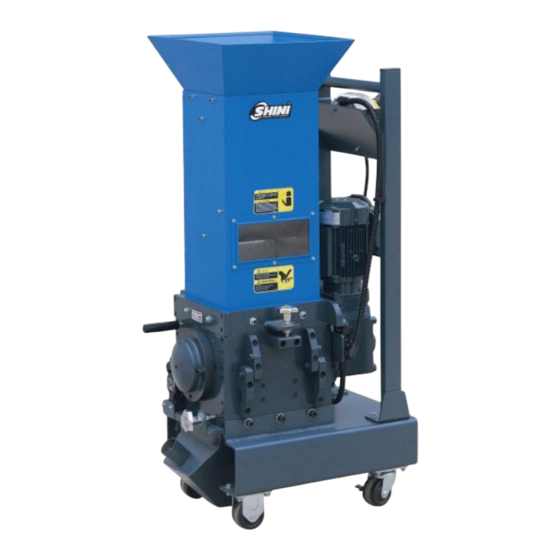
- Page 1 SG-24E Series "Standard" Screenless Granulators Date: June, 2011 Version: V4.1 (English)
-
Page 3: Table Of Contents
Contents General Description ...................9 1.1 Coding Principle..................10 1.2 Feature ....................10 1.3 Technical Specifications ..............12 1.3.1 Technical Specifications ............12 1.3.2 Dimensions................13 1.4 Safety Regulations................14 1.4.1 Safety Signs and Labels............14 1.4.2 Transportation and Storage of the Machine ......16 1.5 Exemption Clause................17 Structural Features and Working Principle..........19 2.1 General Description ................19 2.1.1 Working Principle..............19 2.2 Safety System..................20... - Page 4 2.3.14 Storage Box................32 2.3.15 Storage Box Parts List..............32 2.3.16 Main Body ................33 2.3.17 Main Body Parts List..............33 2.4 Electrical Diagram................34 2.4.1 Main Circuit ................34 2.4.2 Electrical Components List ............35 2.5 Optional Accessories ................36 2.5.1 30-Second Instant Recycle System..........36 2.5.2 Proportional Valve ..............37 2.5.3 Manual Collective Storage Box ..........38 Installation and Debugging ..............39 3.1 Installation Notice................40...
- Page 5 5.1 Granulator doesn't Run ...............50 5.2 Other Reasons for Shutdown..............51 Maintenance and Repair ................52 6.1 Preservation..................52 6.1.1 Replace the Blades ..............52 6.2 Transmission ..................54 6.2.1 Routine Preservation of Reducer ..........54 6.3 Preservation..................54 6.3.1 Daily Check ................54 6.3.2 Weekly Check ................55 6.3.3 Monthly Check................55 6.4 Cleaning....................55 6.5 Maintenance Schedule ...............57...
- Page 6 Table 2-12:Electrical Components List of SG-2436EH/2446E......35 Picture index Picture 1-1:Tooth pitch cutters ................13 Picture 1-2:Dimensions...................13 Picture 2-1:Working Principle................19 Picture 2-2:Safety System ................20 Picture 2-3:Emergency Stop Switch..............21 Picture 2-4:Safety Switch................21 Picture 2-5:Assembly Drawing (SG-2417E)............23 Picture 2-6:Assembly Drawing (SG-2427E(H)) ..........25 Picture 2-7:Assembly Drawing (SG-2436E(H)) ..........27 Picture 2-8:Cutting Chamber ................29 Picture 2-9:Blade Rest ..................30 Picture 2-10:Transmission Parts..............31...
- Page 7 Picture 3-12:Installation of Feed Box, Feed Throat and Storage Box 3 ..45 Picture 3-13:Installation of Feed Box, Feed Throat and Storage Box 4 ..45 Picture 4-1:Opening the Feed Box..............48 Picture 4-2:Opening the storage box ..............48 Picture 4-3:Motor Circuit .................49 Picture 6-1:Replace the Blades ..............52 Picture 6-2:Remove the Fixed Blades.............53 Picture 6-3:Remove the Rotating Blades ............53 7(61)
- Page 8 8(61)
-
Page 9: General Description
Forbidden to process flammable or toxic material! SG-24E series "Standard" screenless granulators are suitable for instant recycling or granulating hard and thick materials. With European-type appearance and compact size, they feature low rotating speed, low abrasion and super soundproof. -
Page 10: Coding Principle
SG - xx xx E - xx Option * E=“Standard” Model Length of Cutting Chamber (cm) Width of Cutting Chamber (cm) Shini Granulators Note: * VR=Loading by High Pressure Air BR=Loading by Bolwer BC=Blower Conveying & Cyclone Dust Collector DS=Dust Separator... - Page 11 Chapter 6, which contains service instructions intended for service engineers. Other chapters contain instructions for the daily operator. Any modifications of the machine must be approved by SHINI in order to avoid personal injury and damage to machine. We shall not be liable for any damage caused by unauthorized change of the machine.
-
Page 12: Technical Specifications
1.3 Technical Specifications 1.3.1 Technical Specifications Table 1-1:Technical Specifications Model SG-2417E SG-2427E(H) SG-2436E(H) 0.75 / 0.86 1.5 / 1.75 Motor Power (kW, 50/60Hz) 0.75 / 0.86 (1.5 / 1.75) (2.2 / 2.55) Rotor Speed (r.p.m, 50/60Hz) Teeth-cutter Material SKD-11 SKD-11 SKD-11 Staggered Blade Number Teeth-cutter Number... -
Page 13: Dimensions
Picture 1-1:Tooth pitch cutters 1.3.2 Dimensions Picture 1-2:Dimensions 13(61) -
Page 14: Safety Regulations
Safety Regulations Follow the instructions in this manual to avoid personal injury and damage to machine components. The following safety measures shall be followed when operating the granulator. 1.4.1 Safety Signs and Labels Electrical installation must only be done by a competent electrician! Before the granulator is opened for servicing and maintenance, always disconnect the power with both the main switch and the control switch on the granulator. - Page 15 No need for regular inspection because all the electrical parts in the control unit are fixed tightly! When operate the granulator, please notice the following signs Hazard High voltage! May lead to casualty or other serious danger. Please cut off the power before repairing. Circuit diagram should only be changed by professionals.
-
Page 16: Transportation And Storage Of The Machine
℃ transported with temperature under +70 . Storage ℃ 1) SG-24E series should be stored indoors with temperature kept from 5 to ℃ and humidity below 80%. 2) Disconnect all power supply and turn off main switch and exigency stop switch. -
Page 17: Exemption Clause
Shini (including employees and agents). Shini is exempted from liability for any costs, fees, claims and losses caused by reasons below: 1. Any careless or man-made installations, operation and maintenances upon machines without referring to the Manual prior to machine using. - Page 18 3. Any operational actions that are not authorized by Shini upon machine, including adding or replacing accessories, dismantling, delivering or repairing.
-
Page 19: Structural Features And Working Principle
2. Structural Features and Working Principle 2.1 General Description SG-24E machine-side granulators are mainly operated beside the moulding machine for small quantity of granulation, so don't put excessive material into it when granulating. The granulator is controlled by the main power switch, start button, stop button, safety switches and emergency stop button. -
Page 20: Safety System
In case the safety system of granulator is changed, our company will not perform our commitment. The replacement of all spare parts will be done by SHINI Company. Picture 2-2:Safety System 2.2.1 Emergency Stop Switch There is one red button on the control panel. -
Page 21: Safety Switch
Picture 2-3:Emergency Stop Switch 2.2.2 Safety Switch On the granulator is equipped the safety position switch for the breaker. In case the position of storage box or feed box is changed or the breaker is loosened, the safety switch will cut off the power supply. There are two safety switches on the granulator: one is located between the feed box and the cutting chamber while the other one is on the inner wall of the cutting chamber, linked with the storage box. - Page 22 1) Check if the feed box has been tightened. 2) Close the feed box, and then tighten the hexagonal screw. 3) Check if the safety switch pin of storage box and the hexagonal screw have been tightened. 22(61)
-
Page 23: Assembly Drawing
2.3 Assembly Drawing 2.3.1 Assembly Drawing (SG-2417E) Note: Please refer to 2.3.2 material list about the parts code. Picture 2-5:Assembly Drawing (SG-2417E) 23(61) -
Page 24: Parts List (Sg-2417E)
2.3.2 Parts List (SG-2417E) Table 2-1:Parts List (SG-2417E) Name Part No. Name Part No. Lower and front box Material-collection case BH10241700110 block Lower frame of the feeding Talon blade S YW40245000000 The front and rear board of BH10241700310 Fixed front blade F1 YW40024500100 feeding box BH10241700410... -
Page 25: Assembly Drawing (Sg-2427E(H))
2.3.3 Assembly Drawing (SG-2427E(H)) Note: Please refer to 2.3.4 material list about the parts code. Picture 2-6:Assembly Drawing (SG-2427E(H)) 25(61) -
Page 26: Parts List (Sg-2427E(H))
2.3.4 Parts List (SG-2427E(H)) Table 2-2:Parts list (SG-2427E(H)) Name Part No. Name Part No. Material-collection Upper box left end plate BH10240000310 case Lower box right end BH10240000010 Upper box rear box block BW30242700410 plate Lower box front box BH10242700610 Upper box right end plate BH10240000210 block Lower box rear box... -
Page 27: Assembly Drawing (Sg-2436E(H))
2.3.5 Assembly Drawing (SG-2436E(H)) Note: Please refer to 2.3.6 material list about the parts code. Picture 2-7:Assembly Drawing (SG-2436E(H)) 27(61) -
Page 28: Parts List (Sg-2436E(H))
2.3.6 Parts List (SG-2436E(H)) Table 2-3:Parts List (SG-2436E(H)) Name Part No. Name Part No. Material-collection case Upper box left end plate BH10240000310 Lower box right end BH10240000010 Upper box rear box block BW30243600710 plate Lower box front box BH10243600610 Upper box right end plate BH10240000210 block Lower box rear box... -
Page 29: Cutting Chamber
2.3.7 Cutting Chamber Picture 2-8:Cutting Chamber 2.3.8 Cutting Chamber Parts List Table 2-4:Cutting Chamber Parts List Quantity Name SG-2417E SG-2427E(H) SG-2436E(H) Front top housing block Left top bearing holder Back top housing block Interlayer 1 Left bottom bearing holder Front bottom housing block Right bottom bearing holder Air exhaust Interlayer 2... -
Page 30: Blade Rest
2.3.9 Blade Rest Picture 2-9:Blade Rest 2.3.9.1 Blade Rest Parts List Table 2-5:Blade Rest Parts List Quantity Name SG-2417E SG-2427E(H) SG-2436E(H) Left bearing block Left bearing sleeve Teeth cutter Staggered blade Right bearing block Spring ring Right bearing block Shaft Bearing Lockup screw Fixing screw... -
Page 31: Transmission Parts
2.3.10 Transmission Parts Picture 2-10:Transmission Parts 2.3.11 Transmission Parts List Table 2-6:Transmission Parts List Quantity Name SG-2417E SG-2427E(H) SG-2436E(H) Motor Gear speed reducer Flange 31(61) -
Page 32: Feed Box, Sound Insulation Box And Check Plate
2.3.12 Feed Box, Sound Insulation Box and Check Plate Picture 2-11:Feed Box, Sound Insulation Box and Check Plate 2.3.13 Feed Box, Sound Insulation Box and Check Plate Parts List Table 2-7:Feed Box, Sound Insulation Box and Check Plate Parts List Quantity Name SG-2417E SG-2427E(H) SG-2436E(H) -
Page 33: Main Body
2.3.16 Main Body Picture 2-13:Main Body 2.3.17 Main Body Parts List Table 2-9:Main Body Parts List Quantity Name SG-2417E SG-2427E(H) SG-2436E(H) Bottom base plate Base left side plate Base right side plate 33(61) -
Page 34: Electrical Diagram
2.4 Electrical Diagram 2.4.1 Main Circuit Picture 2-14:Main Circuit 34(61) -
Page 35: Electrical Components List
2.4.2 Electrical Components List Table 2-10:Electrical Components List of SG-2417E/2427E Symbol Name Specification Part NO. Circuit-breaker* 1.6~2.5A Waterproof installation S1 S2 Safety-switch* 500V YE16147600000 Motor 400V 50Hz Table 2-11:Electrical Components List of SG-2427EH/2436E Symbol Name Specification Part NO. Circuit-breaker* 2.5~4A Waterproof installation S1 S2 Safety-switch*... -
Page 36: Optional Accessories
2.5 Optional Accessories 2.5.1 30-Second Instant Recycle System Picture 2-15:30 Second Instant Recycle System 2.5.1.1 Installation Note: Before operating the 30-second instant recycle system, please carefully read Chapter 3. Connection of electric circuit for the 30-second instant recycle system shall be done by a professional electrician. Prior to first start. -
Page 37: Proportional Valve
2.5.1.3 Checks Daily checks Check no damage to the air pocket and the dust pocket; if damaged, replace them promptly. Check no damage to the conveying pipe; if damaged, replace it promptly. Check if the nozzle is properly connected and sealed. Check if the dust collector is full;... -
Page 38: Manual Collective Storage Box
Picture 2-16:Control box, Valve body 2.5.3 Manual Collective Storage Box Picture 2-17:Manual Collective Storage Box 38(61) -
Page 39: Installation And Debugging
3. Installation and Debugging Read this chapter carefully before installation. Install as following orders to avoid any accident! Be careful! Not to be cut by the sharp blade. Power connection must be done by the professional electrician avoid electrical shock. Caution! Cutters should be laid level,prevent the cutters from self-rotating when do installation, don't let your hands be near to the cutters to avoid... -
Page 40: Installation Notice
3.1 Installation Notice 1) Make sure voltage and frequency of the power source comply with those indicated on the manufacture's plate, which is attached to the machine. 2) Power cable and earth connections should conform with local regulations. 3) Use independent power cable and ON / OFF switch. The cable's dia. Should not smaller than those applied in the control box. -
Page 41: Installation Place
3.2 Installation Place Move the granulator to the proper place and fix its castors. Check and make sure the installation ground is level, there is enough intensity when it is running. Picture 3-2:Installation Place 3.3 Installation of Bearing and Blade Rest 1) Install the bearing 2 bearing washer 1 bearing sleeve 7 into the bearing base 2) Insert the blade shaft 4 into the bearing sleeve vertically 7.Then sleeve the staggered blade 5 and the teeth blade 6 on the bearing spacing. -
Page 42: Installation Of Motor
5) Use screws to fix the left and right bearing base 3 on to the respective bearing base holder 4. Picture 3-4:Installation of Bearing and Blade Rest 2 Caution! cutters should be laid level, prevent the cutters from self-rotating when do installation, don't let your hands be near to the cutters to avoid personal injury. -
Page 43: Installation Of Rotating Blade And Fixed Blade
Picture 3-6:Installation of Motor 2 3.5 Installation of Rotating Blade and Fixed Blade Note: The blade is very sharp edged and wear gloves and take great care before installation to avoid injury! 1) Install the bearing 2, bearing washer 1, bearing sleeve 7 into the bearing base 3. -
Page 44: Installation Of Feed Box, Feed Throat And Storage Box
4) Use a wrench to tight up all the screws on bearing block or cutting chamber and lock them up with right torque (M12x25). 5) After installed the rotating blade rest to the housing, mount fixed blades that correspond with teeth cutters on pressing block and align their holes. Lockup the fixing screw (LOCTITE243 thread fixing glue is recommended). -
Page 45: Picture 3-12:Installation Of Feed Box, Feed Throat And Storage Box 3
3) Upon insertion of the feed throat, its hole shall match that of the feed box. Then tighten it with screw (M8). 4) Buckle the material stopper at the top of the feed box and press it with the feed throat. Picture 3-12:Installation of Feed Box, Feed Throat and Storage Box 3 5) After installation of upper components, carry the storage box with two hands and slightly push in along its track. -
Page 46: Operation Guide
Operation Guide 4.1 Startup Pretest Unpainted part of the machine has been covered with stainless oil. Before use, the stainless oil should be cleaned. 1) Clean with a towel. 2) Wash with a towel dipping with amyl acetate. 4.1.1 Before the First Startup 1) Check whether the granulator is in the level state. -
Page 47: Check The Running Direction Of The Motor
4.2.1 Check the Running Direction of the Motor 1) Check whether the feed box or feed inlet screw is locked up. 2) Check whether the storage box is shut off properly. 3) Ensure the main power switch is in ON position. 4) Check the emergency stop. -
Page 48: Opening The Storage Box
Picture 4-1:Opening the Feed Box 4.3.2 Opening the Storage Box 1) Cut off the power supply of granulator. 2) Loosen the long hexagonal screw. 3) Draw out the storage box. Picture 4-2:Opening the storage box 4.4 Closing the Feed Box and the Storage Box 4.4.1 Closing the Feed Box Note! The feed box shall be tightly closed, otherwise the machine cannot start. -
Page 49: Start And Stop The Granulator
Note! Before closing, clean the interface surface. Be careful! Don't get squeezed and injured. 1) Check no powder or leftover material around the cutting chamber and the storage box; timely remove them if any; 2) Push in the storage box along the track; 3) Tighten the hexagonal screw to fix the storage box. -
Page 50: Trouble Shooting
Trouble Shooting 5.1 Granulator doesn't Run 1) Check the emergency stop switch is at its position; and turn the button in arrow direction (anti-clock) to reset it if not. 2) Check the feed box is fully closed; if not, the machine cannot run; open the door to check the lock clip is tightened or not. -
Page 51: Other Reasons For Shutdown
Failure Possible reasons Troubleshooting methods Upon the main power Too low power supply voltage; Check the power supply; switch is on, push the Lack of phases of power supply; Check the power supply; "start" button, the Motor seized; Check the cutting chamber; motor makes Motor fails. -
Page 52: Maintenance And Repair
Maintenance and Repair 6.1 Preservation At the time of preservation, ensure that no material is left in the machine. 6.1.1 Replace the Blades CAUTION! Warning: Self-rotation exists due to non-balanced forces or unstable barycenter. Wear gloves to avoid being cut and be careful of the sharp blades! When replacing and maintaining the blades, please refer to chapter 5.5, and comply with the installation request of fixed blade and movable blade to assemble it. -
Page 53: Picture 6-2:Remove The Fixed Blades
Each time to replace the blade, the screw and insulation ring must be replaced also. 1) Remove the fixed blades Caution! To avoid self rotation, block the rotating blade with a thick wood block. 1. Remove the screws. 2. Remove the fixed blades. 3. -
Page 54: Transmission
Clean carefully the fixed blades and rotating blades and then install them. CAUTION! Each time to replace the blade, the screw and insulation ring must be replaced also. Install the rotating blades, then the fixed blades, finally the front fixed blades. More details about replacing or maintaining the blades to see chapter 3.5. -
Page 55: Weekly Check
of any damage. 2) Check if the emergency stop switch functions normally. Start the machine and then push the emergency stop switch. When restoring, turn the button in the arrow direction (i.e. anticlockwise). 3) Check the main power switch to see if the functions of start, stop and reverse are normal. - Page 56 6) Clean the inner surface of feed box. 7) Loosen the hexagonal screw and remove the storage box. 8) Clean the storage box. 9) Clean the cutting chamber internally and externally. 56(61)
-
Page 57: Maintenance Schedule
6.5 Maintenance Schedule 6.5.1 About the Machine Model Manufacture date Ф Voltage Frequency Power 6.5.2 Check after Installation Check if the lockup screws of the fixed blades are locked firmly. Check if the flange of the speed reducer has been locked firmly. Installation of electrical elements Voltage: Specs of the fuse: 1 Phase... -
Page 58: Daily Check
6.5.3 Daily Check Check main power switch Check emergency stop switch and reverse switch Check start/stop button Check material keeping back plate (strips) Check main power switch Check emergency stop switch and reverse switch Check start/stop button Check material keeping back plate (strips) Check main power switch Check emergency stop switch and reverse switch Check start/stop button... -
Page 59: Weekly Check
6.5.4 Weekly Check Check if there is any damaged cables Check if there is loose electrical connections Check if there is any damaged cables Check if there is loose electrical connections Check if there is any damaged cables Check if there is loose electrical connections Check if there is any damaged cables Check if there is loose electrical connections Check if there is any damaged cables... -
Page 60: Monthly Check
6.5.5 Monthly Check Check the condition of the speed reducer Check the safety switch of the machine Check the motor overload protector Check if the blades are firmly locked Check the condition of the speed reducer Check the safety switch of the machine Check the motor overload protector Check if the blades are firmly locked Check the condition of the speed reducer... -
Page 61: Half-A-Year Or 1000-Hour-Running Check
6.5.6 Half-a-year or 1000-hour-running Check Check the replacement of speed reducer's lubrication Check the lubrication of bearing、motor and rotating shaft Check the noise during operation Evaluation of the machine condition Check the replacement of speed reducer's lubrication Check the lubrication of bearing、motor and rotating shaft Check the noise during operation Evaluation of the machine condition Check the replacement of speed reducer's lubrication...
Need help?
Do you have a question about the SG-24E Series and is the answer not in the manual?
Questions and answers