Table of Contents
Advertisement
Quick Links
Advertisement
Table of Contents

Related Manuals for Shini SG-L


Summary of Contents for Shini SG-L
- Page 1 SG-L Screenless Granulators Date: Dec. 2021 Version:Ver. A (English)
-
Page 3: Table Of Contents
Contents General Description ..................6 1.1 Coding Principle ..................7 1.2 Feature ....................7 1.3 Safety Regulations .................. 9 1.3.1 Safety Regulations ............... 9 1.3.2 Transportation and Storage of the Machine ....... 11 1.4 Exemption Clause ................. 12 Structural Features and Working Principle ..........13 2.1 General Description ................ - Page 4 4.4 Start and Stop the Granulator ............... 22 4.4.1 Before the First Startup .............. 23 4.4.2 Check the motor’s running direction ........... 23 4.4.3 After Startup for 2 Hour .............. 23 4.4.4 After First Startup for 20~30 Hours ..........24 Trouble-shooting ..................
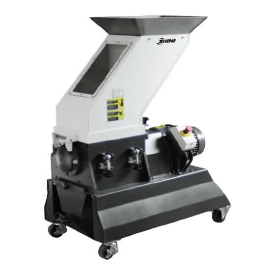
- Page 5 Table Index Table 6-1:Blade and Other Fixing Screws’ Torque Table ....... 26 Picture Index Picture 1-1:Screenless Granulator SG-L36 ............6 Picture 2-1:Working Principle ................13 Picture 2-2:Emergency Stop Switch ..............14 Picture 2-3: Safety Switch ................15 Picture 2-4:Manual Collection Bin ..............15 Picture 2-5:Regrind Conveying via Blower &...
-
Page 6: General Description
Forbidden to process flammable or toxic material ! SG-L Screenless Granulator is applicable to granulating hard long or strong flexible sprues for instant recycling and a few rejects. It features small size, low speed and wear, and super silence, with low speed structure, and particle granules of little dust. -
Page 7: Coding Principle
1.1 Coding Principle Options Length of Cutting Chamber (CM) Low speed Shini Granulator 1.2 Feature Adopt TECO brand gear motor that features stable performance, long service life and large torque. Break large spurs into smaller pieces, and teeth cutter bites the materials into the desired size with less dust and ready to be reused ... - Page 8 Chapter 6, which contains service instructions intended for service engineers. Other chapters contain instructions for the daily operator. Any modifications of the machine must be approved by SHINI in order to avoid personal injury and damage to machine. We shall not be liable for any damage caused by unauthorized change of the machine.
-
Page 9: Safety Regulations
Safety Regulations Follow the instructions in this manual to avoid personal injury and damage to machine components. The following safety measures shall be followed when operating the granulator. 1.3.1 Safety Regulations Electrical installation must only be done by a competent electrician! Before the granulator is opened for servicing and maintenance, always disconnect the power with both the main switch and the control switch on the granulator. - Page 10 Attention! No need for regular inspection because all the electrical parts in the control unit are fixed tightly! When operate the granulator, please notice the following signs. Hazard High voltage! May lead to casualty or other serious danger. Please cut off the power before repairing. Circuit diagram should only be changed by professionals.
-
Page 11: Transportation And Storage Of The Machine
-25℃ to +55℃ for long distance transportation and for a short distance, it can be transported with temperature under +70℃. Storage 1) SG-L series should be stored indoors with temperature kept from 5℃ to 40℃ and humidity below 80%. 2) Disconnect all power supply and turn off main switch and control switch. -
Page 12: Exemption Clause
Shini (including employees and agents). Shini is exempted from liability for any costs, fees, claims and losses caused by reasons below: 1. Any careless or man-made installations, operation and maintenances upon machines without referring to the Manual prior to machine using. -
Page 13: Structural Features And Working Principle
2. Structural Features and Working Principle 2.1 General Description SG-L series belong to the granulator used beside the IMM, which are designed for injection molding machine to crush a small amount of materials. Don’t put too many materials into crushing. The granulators are controlled by main power switch, emergency stop button, start button, stop button and safety switches. -
Page 14: Safety System
The maintenance and preservation of safety system shall be done by professional staff. In case the safety system of granulator is changed, our company will not perform our commitment. The replacement of all spare parts will be done by SHINI Company. -
Page 15: Door Lock
Safety switch Picture 2-3: Safety Switch 2.2.3 Door lock The machine’s door lock is a star nut, which can extent the time to open the feed box to avoid human injury. When opening the feed box, loosen the star nut, and it will last for a period of time that is totally enough to stop the granulator, so as to avoid personal injury. -
Page 16: Cutter
Picture 2-5:Regrind Conveying via Blower & Cyclone (PC type) 2.3.3 Cutter On the basis of standard cutter 5mm, cutter 4mm or 6mm is provided for option. Picture 2-6:Cutter Dimension 2.3.4 30-Sec. Instant Recycling System –VR Type The 30-sec. instant recycling system utilizes the high-pressure blower to blow the regrinds in the material storage tank to the proportional mixer and reuse the regrinds after mixing, so that the sprues will have physical properties and color changes due to oxidation and humidification, thus improving the products quality. -
Page 17: 30-Sec. Instant Recycling System -Pr Type
Picture 2-7:Installation of 30-Sec. Instant Recycling System – VR Type 30-sec. Instant Recycling System –PR Type 2.3.5 The 30-sec. instant recycling system utilizes the high-pressure blower to blow the regrinds in the material storage tank to the proportional mixer and reuse the regrinds after mixing, so that the sprues will have physical properties and color changes due to oxidation and humidification, thus improving the products quality. -
Page 18: Installation And Debugging
3. Installation and Debugging This series of models can only be used in working environment with good ventilation. Read through this chapter before installation. Must abide the following installation steps to avoid personnel injuries or damage of the machine! Take great care of handing the blades because they are very sharp and may cause cutting injuries! Power supply of the machine should be handled by qualified electricians! Caution! -
Page 19: Power Connectors
3.1 Power Connectors 1) Make sure voltage and frequency of the power source comply with those indicated on the manufacture's plate, which is attached to the machine. 2) Power cable and earth connections should conform with local regulations. 3) Use independent power cable and ON / OFF switch. The cable's diameter should not smaller than those applied in the control box. -
Page 20: Picture 3-2: Installation Diagram
Picture 3-2: Installation Diagram The machine must be installed in the environment with good ventilation. 20(36) -
Page 21: Operation Guide
Operation Guide 4.1 Clean the Anti-rust Oil The unpainted parts of the machine have been greased with anti rust oil before delivery. Make sure to clean the anti rust oil before starting the machine. 1) Wipe with a rag first. 2) Then, dip the rag with Tianna water to clean it. -
Page 22: Shut The Feed Box And Storage Box
2) Loosen the star screw. 3) Remove the storage box. Picture 4-2:Open the Storage Box 4.3 Shut the Feed Box and Storage Box 4.3.1 Shut the Feed Box Notice! Make sure the feed box is closed. Otherwise, the machine can’t start. 1) Check to ensure there is no powder left in the interface or corners. -
Page 23: Before The First Startup
Power button Emergency stop button Picture 4-3:Motor Circuit Breaker CAUTION: If there are ungrinded materials in the feed box or cutting chamber, the granulator shall NOT be stopped, otherwise the crew materials will blockade the rotator and the motor will be overloaded next time you start the machine up. 4.4.1 Before the First Startup 1) Check whether the granulator is in the level state. -
Page 24: After First Startup For 20~30 Hours
4.4.4 After First Startup for 20~30 Hours After the machine runs at full load for 20 ~ 30 hours, use a thermometer to test if the gear motor’s surface temp. is ≤70℃, and check whether the gear motor leaks oil. 24(36) -
Page 25: Trouble-Shooting
Trouble-shooting 5.1 Granulator Can Not Work 1) Check if the emergency stop has been reset. If not, rotate the button anti-clockwise to reset it. 2) Check if the feed box is completely closed. If not, the machine could not be started. 3) Check the clearance between the blades. -
Page 26: Maintenance And Repair
Maintenance and Repair Check whether the electrical Check whether the sight glass is in components in the control box are good condition before starting up. loose or not. Period: weekl y. Period: dail y. Check whether the emergency stop switch works normall y. Period: dail y. -
Page 27: Installation Of Motor
1) Install the right bearing seat, bearing sleeve and bearing retaining ring. 2) Put the blade rest 2 into the cutting chamber 1 to make the bearings at both ends match with the lower groove of the bearing seat. 3) Fix the left and right bearing seats 3 with screws on the left and right end plates. -
Page 28: Picture 6-4:Installation Of Gear Motor 1
Picture 6-4:Installation of Gear Motor 1 2) Place the gear motor on machine frame and move it to proper position, and install the chain of the chain coupling. Then, use set screws to lock up the shaft coupling, and install the yellow cover on the shaft coupling. Picture 6-5:Installation of Gear Motor 2 3) Use the inner hex. -
Page 29: Installation Of Feed Box And Storage Box
Be careful! The blades must be placed steady, and prevent the blades from self-rotating during installation. When operating, keep your hands away from the cutters to prevent personnel injury. Installation of Feed Box and Storage Box 1) Install the feed box hinge on the left bearing seat of the cutting chamber, and fix it with M8 screws. -
Page 30: Repair
6.4 Repair All the repair must be done by professionals to avoid damage to machine and harm to human body. 6.4.1 Replace the Blades Warning! When installing the cutters, the rotating blades of the granulator will rotate on its own due to unbalanced force! Be careful! It will also rotate on its own when the center of gravity is unstable. -
Page 31: Picture 6-10:Dismantle Fixed Blades
1. Remove the fixed blades Caution! To avoid self rotation, block the rotating blade with a thick wood block. 1) Remove the set screws. 2) Remove the fixed blades. 3) Clean the installation surface of the blade. Picture 6-10:Dismantle Fixed Blades 2. -
Page 32: Picture 6-12:Installation Of Fixed Blades And Rotating Blades 1
The screws and washers must be all replaced during each blade replacement. Install the rear fixed blade at first, and the front fixed blade. Then, install the rotating blades. Specific installation steps please refer to the Installation of the Fixed Blades and Rotating Blades. Caution! Wear protective gloves before operation because the blades are very sharp. -
Page 33: Maintenance
Picture 6-14:Installation of Fixed Blades and Rotating Blades 3 Note: In order to avoid personal injury and machine damage, make sure to tighten the fixed blade’s set screw. 6.5 Maintenance When carrying out maintenance, ensure that there is no material left in the granulator. -
Page 34: Weekly Check
and then stop it via Emergency Stop. Rotate the button anti-clockwise to rest the Emergency Stop. 3) Check the main power switch, start/stop button. 6.5.3 Weekly Check 1) Check the power wire to see whether there is any damage. If so, replace it immediately. -
Page 35: Maintenance Schedule
6.7 Maintenance Schedule 6.7.1 About the Machine Model: No.: Manufaturing date : Ф Voltage: Frequency: Total power: 6.7.2 Check after Installation Check whether the locking screw of the fixed blade is locked up. Check whether the gear motor flange is locked up. Electrical Installation Voltage: Fuse melt current: 1 Phase... -
Page 36: Year Checking
Check lubrication of bearing. Check the coupling. Evaluation of the machine condition. 6.7.7 3 Year Checking PC board renewal. No fuse breaker renewal. 36(36)
Need help?
Do you have a question about the SG-L and is the answer not in the manual?
Questions and answers