Table of Contents
Advertisement
Quick Links
Advertisement
Table of Contents

Subscribe to Our Youtube Channel
Related Manuals for Shini SG-36E Series


Summary of Contents for Shini SG-36E Series
- Page 1 SG-36E "Standard" Central Granulators Date: Apr. 2013 Version: Ver.A (English)
-
Page 3: Table Of Contents
Contents General Description ..................9 1.1 Coding Principle ..................10 1.2 Feature....................10 1.3 Technical Specifications................ 12 1.3.1 Technical Specifications ............. 12 1.3.2 Dimensions................. 13 1.4 Safety Regulations ................13 1.4.1 Safety Signs and Labels ............. 13 1.4.2 Transportation and Storage of the Machine........ 14 1.5 Exemption Clause ................. - Page 4 2.3.14 Main Body................... 27 2.3.15 Main Body Parts List..............27 2.4 Wiring Diagram ..................28 2.4.1 Main Circuit................. 28 2.4.2 Control Circuit ................29 2.4.3 Electrical Components Layout ............ 31 2.4.4 Electrical Components List ............32 2.5 Electrical Components Instruction............34 2.6 Optional Accessories ................
- Page 5 6.2.2 Adjust the V-belt ................. 51 6.3 Lubrication .................... 51 6.3.1 Lubricating Oils................51 6.3.2 Lubricating Method ..............52 6.4 Maintenance ..................52 6.4.1 Daily Maintenance ..............52 6.4.2 Weekly Checking ................ 53 6.4.3 Monthly Checking ............... 53 6.5 Cleaning....................53 6.6 Maintenance Schedule................
- Page 6 Picture 1-1:Dimensions .................. 13 Picture 2-1:Working Principle ................. 17 Picture 2-2:Emergency Stop ................18 Picture 2-3:Safety Switch ................18 Picture 2-4:Locking Screw ................19 Picture 2-5:Assembly Drawing ............... 20 Picture 2-6:Cutting Chamber................22 Picture 2-7:Blade Rest ................... 23 Picture 2-8:Transmission Parts ..............24 Picture 2-9:Screen ..................
- Page 7 Picture 4-1:Start / Stop of the Machine ............45 Picture 6-1:Remove the Fixed Blades............49 Picture 6-2:Daily Maintenance of V-belt ............51 Picture 6-3:Adjust the V-belt ................51 Picture 6-4:Bearing Coverv ................52 Picture 6-5:Lock Screw .................. 53 7(56)
- Page 8 8(56)
-
Page 9: General Description
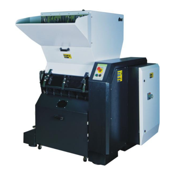
Forbidden to process flammable or toxic material! SG-36E series of "Standard" central granulators are built to conform to sound-proof models both in safety configuration and operation security. They are suitable for centralized recycling of wastes and rejected products from injection, blow moulding and extrusion lines. -
Page 10: Coding Principle
R=For Stainless Steel Made Feed Port and Storage Tank 1.2 Feature Standard configuration 1) SG-36E series adopts paddle blades design. 2) The blade material is imported steel to ensure high quality and high durability. 3) Staggered blades design can decentralize working load when granulating to increase cutting efficiency. - Page 11 Chapter 6, which contains service instructions intended for service engineers. Other chapters contain instructions for the daily operator. Any modifications of the machine must be approved by SHINI in order to avoid personal injury and damage to machine. We shall not be liable for any damage caused by unauthorized change of the machine.
-
Page 12: Technical Specifications
1.3 Technical Specifications 1.3.1 Technical Specifications Chart 1-1:Technical Specifications Model SG-3650E SG-3675E Motor Power (kW) (50 / 60Hz) 18.5 / 22.2 30 / 36 Rotor Speed (rpm) (50 / 60Hz) 540 / 650 540 / 650 Number of Fixed Blades Number of Rotating Blades Cutting Chamber (mm) 360×500... -
Page 13: Dimensions
1.3.2 Dimensions Picture 1-1:Dimensions 1.4 Safety Regulations Follow the instructions in this manual to avoid personal injury and damage to machine components. The following safety measures shall be followed when operating the granulator. 1.4.1 Safety Signs and Labels Electrical installation must only be done by a competent electrician! Before the granulator is opened for servicing and maintenance, always disconnect the power with both the main switch and the control switch on the granulator. -
Page 14: Transportation And Storage Of The Machine
1.4.2 Transportation and Storage of the Machine Transportation 1) SG-36E series of granulators are packed in plywood cases with wooden pallet at the bottom, suitable for quick positioning by fork lift. 2) After unpacked, castors equipped on the machine can be used for ease of movement. - Page 15 +55℃ for long distance transportation and for a short distance, it can be transported with temperature under +70℃. Storage 1) SG-36E series should be stored indoors with temperature kept from 5℃to 40 ℃ and humidity below 80%. 2) Disconnect all power supply and turn off main switch and exigency stop...
-
Page 16: Exemption Clause
Shini (including employees and agents). Shini is exempted from liability for any costs, fees, claims and losses caused by reasons below: 1. Any careless or man-made installations, operation and maintenances upon machines without referring to the Manual prior to machine using. -
Page 17: Structural Features And Working Principle
2. Structural Features and Working Principle 2.1 General Description SG-36E granulator is designed for grinding plastic waste to granulate for recycling. The plastic waste should be free from metal parts and contamination before granulating. Mount magnet at the feed port to prevent metal scraps from getting into cutting chamber and brings damage to the blades. -
Page 18: Safety System
2.2 Safety System The granulator has knives which rotate at high speed, therefore equip-ped with a safety system to avoid personal injury. The safety system must not be changed or modified in any circumstances. If the safety sy-stem of granulator is changed or modified, the machine can be danger-ous to use, presenting a serious rick of personal injury. -
Page 19: Picture 2-4:Locking Screw
The star knobs which on the hopper and screen frame are very important components in the safety system of the granulator. When it unscrewed, the blades will be stopped. To avoid personal injuries. Picture 2-4:Locking Screw NOTE! Do not change the screw length of locking screw. Before turning on the machine, the screws on feeding hopper and screen frame must be tightened to deadlock. -
Page 20: Assembly Drawing
2.3 Assembly Drawing 2.3.1 Assembly Drawing Note: Please refer to 2.3.2 material list about the parts code. Picture 2-5:Assembly Drawing 20(56) -
Page 21: Parts List
2.3.2 Parts List Chart 2-1:Parts List Part No. Name SG-3650E SG-3675E Feed box assembly Cutting chamber assembly BH85365000010 BH85367500010 Material collection assembly Base assembly Pneumatic spring fixing plate 1 Drive assembly Shield assembly Anti-vibration screw BH10161800010 BH10161800010 Anti-vibration case BH10364512810 BH10364512810 Anti-vibration pad YW03162000000... -
Page 22: Cutting Chamber
2.3.3 Cutting Chamber Picture 2-6:Cutting Chamber 2.3.4 Cutting Chamber Parts List Chart 2-2:Cutting Chamber Parts List SG-3650E SG-3675E Name Part No. Quantity Part No. Quantity Front block BW30365000410 BW30367504010 Left side plate of cutting BW30367518010 BW30367518010 chamber Position localized bolt YW09105000000 YW09105000000 Inner hexagon cylindrical... -
Page 23: Blade Rest
2.3.5 Blade Rest Picture 2-7:Blade Rest 2.3.5.1 BladeRest Parts List Chart 2-3:BladeRest Parts List SG-3650E SG-3675E Name Part No. Quantity Part No. Quantity Pressing block of rotating BH11365000810 BH11367511010 blades Knife jig shaft BH11365000710 BH11367512010 Bearing YW11221500000 YW11221500000 Upper part of bearing block BW30003600210 BW30003600210 Oil injection nozzle... -
Page 24: Transmission Parts
2.3.6 Transmission Parts Picture 2-8:Transmission Parts 2.3.7 Transmission Parts List Chart 2-4:Transmission Parts List SG-3650E SG-3675E Name Part No. Quantity Part No. Quantity Taper sleeve YW30254800000 YW30254800000 Motor belt pulley YW30180400000 YW30180400000 Adjusting plate of motor Motor YM10418300200 YM10420700200 V belt YR00059000000 YR00059000000 Big belt pulley... -
Page 25: Screen
2.3.8 Screen Picture 2-9:Screen 2.3.9 Screen Parts List Chart 2-5:Screen Parts List SG-3650E SG-3675E Name Part No. Quantity Part No. Quantity Screen BL55365000220 BL55367502020 2.3.10 Screen Bracket Picture 2-10:Screen Bracket 2.3.11 Screen Bracket Parts List Chart 2-6:Screen Bracket Parts List SG-3650E SG-3675E Name... -
Page 26: Feed Box And Cutting Chamber
2.3.12 Feed Box and Cutting Chamber Picture 2-11:Feed Box and Cutting Chamber 2.3.13 Feed Box and Cutting Chamber Parts List Chart 2-7:Feed Box and Cutting Chamber Parts List SG-3650E SG-3675E Name Part No. Quantity Part No. Quantity Feed port Fender trim strip 1 Fender trim strip fixing plate Fender trim strip 3 Fender trim strip 4... -
Page 27: Main Body
2.3.14 Main Body Picture 2-12:Main Body 2.3.15 Main Body Parts List Chart 2-8:Main Body Parts List SG-3650E SG-3675E Name Part No. Quantity Part No. Quantity Rack Right outshell Electrical control box Control box door 27(56) -
Page 28: Wiring Diagram
2.4 Wiring Diagram 2.4.1 Main Circuit Picture 2-13:Main Circuit 28(56) -
Page 29: Control Circuit
2.4.2 Control Circuit Picture 2-14:Control Circuit 1 29(56) -
Page 30: Picture 2-15:Control Circuit 2
Picture 2-15:Control Circuit 2 30(56) -
Page 31: Electrical Components Layout
2.4.3 Electrical Components Layout Picture 2-16:Electrical Components Layout 31(56) -
Page 32: Electrical Components List
2.4.4 Electrical Components List Chart 2-9: Electrical Components List SG-3620E Symbol Name Specification Part NO. Gate circuit breaker* YE41109000000 K1 K2 Contactor 220VAC 50/60Hz YE00602622000 Contactor 220VAC 50/60Hz YE00602522000 Subsidiary contactor 1NO+1NC YE00691100100 Contactor 220V 50/60Hz YE00602822000 Safety realy 230V 50/60Hz YE04372100000 Timer 230V 50/60Hz... -
Page 33: Chart 2-10:Electrical Components List Sg-3675E
Chart 2-10:Electrical Components List SG-3675E Symbol Name Specification Part NO. Gate circuit breaker* 125A YE41161200000 K1 K2 Contactor 220VAC 50/60Hz YE00503500000 Subsidiary contactor 1NO+1NC YE00691100100 Contactor 220VAC 50/60Hz YE00602822000 Subsidiary contactor 1NO+1NC YE00691100100 Contactor 220V 50/60Hz YE00504400000 Subsidiary contactor YE00592110100 Safety realy 230V 50/60Hz YE04372100000... -
Page 34: Electrical Components Instruction
2.5 Electrical Components Instruction Overload relay Picture 2-17:Overload Relay Description of overload relay: 1) Terminal for contact coil A2. 2) Setting current adjusting scale. 3) Reset (blue). H: manual reset A: automatic reset 4) Switch position indication (green). 5) Test button(red). Tripping of a manual-resetting is indicated by a pin projecting at the front plate. -
Page 35: Optional Accessories
2.6.2 Blades International code Material China Japan SKD11 Cr12MoV SKD11 2.6.3 Flywheel Picture 2-19:Flywheel Increase inertia, thereby increasing the cutting ability. At the same time can result in a more balanced force and longer work life. SG-36E series is optional. 35(56) -
Page 36: Installation And Debugging
3. Installation and Debugging Read through this chapter before installation. Install as following orders to avoid any accident! Be careful! Not to be cut by the sharp blade. Power connection must be done by the professional electrician to avoid electrical shock. Caution! cutters should be laid level, prevent the cutters from self-rotating when do installation, don't let your hands be near to the cutters to avoid... -
Page 37: Installation Notice
3.1 Installation Notice 1) Make sure voltage and frequency of the power source comply with those indicated on the manufacture's plate, which is attached to the machine. 2) Power cable and earth connections should conform with local regulations. 3) Use independent power cable and ON / OFF switch. The cable's dia. Should not smaller than those applied in the control box. -
Page 38: Installation Place
3.2 Installation Place Make enough installation space to facilitate the repair and maintenance. Check and make sure the installation ground is level, and there is enough intensity when it is running. Use spirit level to adjust the cutting chamber to the level position. Picture 3-2:Installation Place 3.3 Installation of Blade Rest and Bearing 1) Heat the bearing and lay it to be entrapped into the blade rest. -
Page 39: Installation Of Belt Pulley And Motor
Picture 3-3:Installation of Blade Rest and Bearing 3.4 Installation of Belt Pulley and Motor 1) Interpose the key to the key groove and then install the driven wheel. Picture 3-4:Installation of Belt Pulley and Motor 1 2) Lay lockup ring in the hole of the driven wheel and make both positions of the hole to match each other then screw the hexagon socket cap screw. -
Page 40: Picture 3-6:Installation Of Belt Pulley And Motor 3
Picture 3-6:Installation of Belt Pulley and Motor 3 7) Adjust the balance of the driving wheel and driven wheel: place spirit level between the driving wheel and the driven wheel to observe whether the mercury column is in the middle. If not, adjust the driving wheel (note: NOT the driven wheel) to make the driven wheel and driving wheel in balance. -
Page 41: Installation Of Fixed Blades And Rotating Blades
3.5 Installation of Fixed Blades and Rotating Blades Notice! The blades are very sharp, so use protective gloves at the installation to avoid being cut. Installation steps: 1) Lay the rotating blades into the knife groove in the knife rest to make them match and then cover the pressing block. -
Page 42: Installation Of Regrind Storage Bin, Screen And Screen Bracket
Installation of Regrind Storage Bin, Screen and Screen Bracket 1) Put the screen into the screen bracket and screw the screen down with 2 screws. 2) Lift up the screen bracket and make its iron rod slide along with both sideboards into the fixing grooves. -
Page 43: Picture 3-12:Installation Of Screen, Screen Frame And Storage Bin 2
Picture 3-12:Installation of Screen, Screen Frame and Storage Bin 2 4) Install pneumatic spring fixing block to the lower left side of the Picture 3-13:Installation of Screen, Screen Frame and Storage Bin 3 5) Install pneumatic spring and make its lower end link to the fixing pole of the machine base. -
Page 44: Operation Guide
3) Push or pull the rotor and blades to see if there is any loose connection. If any of the above situation is found, please contact local representative or SHINI company for help. 4.1 Prestart Check 1. The unpainted parts of the machine are protected with oil prior to delivery and transport. -
Page 45: Start / Stop Of The Machine
Change two income wires of the motor. d) Restart and recheck. 4.3 Start / Stop of the Machine SG-36E series of granulator use the start and stop button located on the control panel for controlling. Picture 4-1:Start / Stop of the Machine... -
Page 46: Open The Feed Box
4.4 Open the Feed Box Turn off the power before opening the feed box and screen frame of the SG-36E series of granulator. Becareful! Since the blades are very sharp and can cause personal injuries. Clean the inside surface of the feed box before closing it. 1) Check that the feed-in case is empty, and then start the machine. -
Page 47: Trouble Shooting
Trouble Shooting 5.1 Granulator Can Not Work 1. Check if the emergency stop button is reset or not. 2. Check if the feed box is closed fully, if not, or the star knob has not been locked fully, the machine can not be started. 3. -
Page 48: Maintenance And Repair
Maintenance and Repair 1. Check the main power switch (daily). 2. Check whether the fender trim strip is damaged (daily). 3. Check whether the emergency stop function works normally (daily). 4. Check whether the run/stop button works normally (daily). 5. Check whether the screw between feed box and screen bracket is damaged (daily);... -
Page 49: Repair
6.1 Repair All the repair work should be done by professionals in order to prevent personal injuries and damage of the machine. 6.1.1 Changing the Blade Be careful when holding the blades, they are sharp and can cause personal injury. Use protective gloves! Do not install the cutters by working together, because this could bring personal injury. -
Page 50: Transmission
4. Loosen and remove the screws of the back blades. 5. Loosen and remove the hexagon socket cap screw, remove the pressing block and the blades ,clean the supporter box. 3) Mounting blades Clean the fixed blades and rotating blades carefully before mounting the blades. -
Page 51: Adjust The V-Belt
Picture 6-2:Daily Maintenance of V-belt Motor 50Hz 18.5/22kW 30/37kW 45-55kW New belt 15mm 14mm 15mm Used belt (after be 19mm 19mm 19mm used 6 months) Motor 60Hz 18.5/22kW 30/37kW 45-55kW New belt 18mm 17mm 16mm Used belt (after be 23mm 23mm 20mm used 6 months) -
Page 52: Lubricating Method
Bp:BP Grease LGEP 2 ESSO:Beacon Ep2, Beacon EP2 Mobil:Mobilux EP2 Shell:Shell Alvania EP2 Texaco:Multifak Ep2, Novotex Grease EP2 6.3.2 Lubricating Method Inject lubricating oil via throat with an oil greaser. (It had better add lubricant once for three months) If the granulator has not keen used for a long time, please grease anti-rust oil in blade rest, fixed blade, rotating blade, cutting chamber and screws to avoid dust. -
Page 53: Weekly Checking
Picture 6-5:Lock Screw 6.4.2 Weekly Checking 1) Check if the electric wires are worn out or damaged. Replace the broken wires. 2) Check the function of safety switch. 3) Check the safety switch of feed box and storage bin. 6.4.3 Monthly Checking 1) Check if the V blet is damaged or not. - Page 54 9) Loosen the lock wiring in the screen bracket and remove the screen bracket. Note! Lift the screen with hands so it would not fall down. 10) Take out the screen. 11) Catching to the screen and take it out outwardly. 12) Clean the regrind storage bin, screen bracket and the screen.
-
Page 55: Maintenance Schedule
6.6 Maintenance Schedule 6.6.1 About the Machine Model Manufacture date Voltage Ф Frequency Power 6.6.2 Check After Installation Check the gap between fixed blade and rotating blade. (0.4~0.5mm). Check the rotating balance of the belt wheel. Electrical Installation Voltage: Specs of the fuse: 1 Phase 3 Phase Check phase sequence of the power supply. -
Page 56: Check Half-Yearly Or Every 1000 Running Hours
Check motor reversed running function. Check the tightness of the blades. Check whether clamp ring of pulley is fastened. Check belt tension. 6.6.6 Check Half-yearly or Every 1000 Running Hours Check or replace lubrication for gear motor. Check lubrication of bearing. Check coupling.
Need help?
Do you have a question about the SG-36E Series and is the answer not in the manual?
Questions and answers